A log splitter that takes thirty seconds per cycle. A dump trailer that strains to lift its bed. A hydraulic press that wastes power on every approach stroke. These are the daily costs of forcing a single-stage pump to do work it was never designed to do efficiently.
You don’t need a larger engine. You don’t need two separate pumps. You need a 2 stage hydraulic pump.
A 2 stage hydraulic pump combines high-flow/low-pressure and low-flow/high-pressure operation in one housing. It moves an actuator quickly when resistance is low. Then it switches automatically to high-pressure mode when the load increases. This design cuts cycle time, reduces power consumption, and simplifies system layout for equipment builders and maintenance engineers.
In this guide, you’ll learn exactly how a 2 stage hydraulic pump works. You’ll see how it compares to single-stage and variable-displacement pumps, where it delivers the most value, and how to size and select one for your application. You’ll also get real manufacturer specifications, a hydraulic pump sizing guide with worked examples, and maintenance practices that extend pump life.
What Is a 2 Stage Hydraulic Pump?

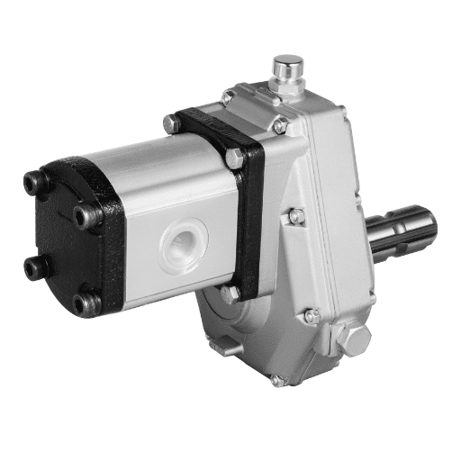
A 2 stage hydraulic pump is a single pump unit that contains two distinct pumping sections. The first section moves a large volume of hydraulic fluid at relatively low pressure. The second section moves a smaller volume at much higher pressure. An internal valve arrangement switches flow between the two sections based on system demand.
Engineers also call these units two stage hydraulic pumps, HI/LO pumps, two-speed pumps, or, in the log splitter market, simply log splitter pumps. Most units built for mobile and industrial equipment use a gear-pump architecture. Gear pumps tolerate contamination, run at high speed, and cost less than piston alternatives.
The key components of a typical 2 stage hydraulic gear pump include:
- Inlet port — draws fluid from the reservoir
- High-flow gear set — the larger displacement stage for fast actuator movement
- High-pressure gear set — the smaller displacement stage for force-intensive work
- Unloader valve — redirects flow from the high-flow stage back to inlet when transition pressure is reached
- Check valves — ensure one-way flow between stages and the outlet
- Relief valve — limits maximum system pressure to protect the pump and components
- Drive shaft — connects to the engine, motor, or power take-off
Because both stages share one housing and one drive shaft, a 2 stage hydraulic pump replaces two separate pumps with a single compact component. That reduces plumbing, mountings, and drive hardware while still delivering dual-mode performance.
How Does a 2 Stage Hydraulic Pump Work?
The operation of a 2 stage hydraulic pump follows a clear pressure-driven sequence. Understanding each phase helps equipment builders diagnose problems, size systems correctly, and avoid common installation mistakes. For a technical perspective on this design, see this two-stage pump explainer.
Stage 1 — High-Flow, Low-Pressure Mode
When the actuator starts moving and load resistance is low, the pump operates in its high-flow stage. The larger gear set draws fluid from the reservoir and delivers it to the outlet at a high flow rate. Pressure during this phase is moderate — typically up to the pump’s preset unload pressure, often around 650 PSI for standard log-splitter pumps.
Because pressure is still low, the hydraulic power required is also low. The actuator moves quickly without demanding excessive engine power. This is the “fast approach” phase that shortens cycle time.
The Transition — Automatic Stage Switching
As the actuator meets resistance, system pressure rises. When pressure reaches the factory-set unload threshold, the unloader valve opens. Flow from the high-flow stage is diverted back to the inlet or reservoir rather than continuing to the outlet.
A check valve between the high-flow stage and the outlet closes, preventing backflow. At the same time, the smaller high-pressure gear set continues to deliver fluid to the system. The pump has now shifted from speed mode to force mode.
Typical unload pressure settings range from 400 to 900 PSI, with 650 PSI being a common factory preset. Adjustable models allow engineers to tune the switch point to match the application load curve.
Stage 2 — Low-Flow, High-Pressure Mode
In the second stage, the smaller gear set generates high pressure at a reduced flow rate. Industrial two-stage gear pumps commonly reach 3,000 PSI continuous pressure, with some models rated higher for short periods. The actuator continues to move, but more slowly, while producing the force needed for the work phase.
This phase determines the maximum horsepower requirement for the prime mover. A pump delivering 4 GPM at 3,000 PSI requires roughly 7 input horsepower at 85% efficiency — far less than running 16 GPM at 3,000 PSI continuously.
What Happens When Load Is Removed
When the actuator reaches the end of its stroke or the load decreases, system pressure drops. The unloader valve closes, the check valve reopens, and the high-flow stage resumes delivery. The cycle can repeat without manual intervention.
This automatic switching is what makes a 2 stage hydraulic pump so efficient for cyclic equipment. It uses high flow only when it is useful and high pressure only when it is necessary.
2 Stage Hydraulic Pump vs Single Stage: Key Differences
Choosing between a single-stage and a two-stage pump depends on the application load profile. The table below summarizes the practical differences.
| Feature | Single-Stage Pump | 2 Stage Hydraulic Pump |
|---|---|---|
| Flow/pressure curve | One fixed displacement | High flow/low pressure + low flow/high pressure |
| Best for | Continuous moderate loads | Cyclic fast-approach / high-force work |
| Cycle time | Slower for speed-then-force cycles | Faster for speed-then-force cycles |
| Power demand | Higher if sized for peak pressure | Lower because high pressure is used only when needed |
| First cost | Lower | Moderate |
| Complexity | Simpler | More complex due to unloader and check valves |
| Maintenance | Fewer internal valves | More valve components to inspect |
Use a single-stage pump when the system needs steady flow at a relatively constant pressure. Use a 2 stage hydraulic pump when the machine must move quickly through most of its stroke, then generate high force for a short work phase. Log splitters, compactors, and hydraulic presses are classic examples. If you need a more detailed comparison, you can read our article on Two Stage Hydraulic Pump vs Single Stage.
Need help matching a pump to your machinery? Contact LOYAL INDUSTRIAL PTE. LTD. for a customized hydraulic system recommendation based on your flow, pressure, and duty-cycle requirements.
2 Stage Hydraulic Pump vs Variable-Displacement Piston Pump
A variable-displacement piston pump can also match flow and pressure to load demand, but it does so continuously rather than in two discrete stages. The choice between the two technologies involves cost, complexity, and duty-cycle considerations.
| Feature | 2 Stage Hydraulic Gear Pump | Variable-Displacement Piston Pump |
|---|---|---|
| Pressure control | Two fixed modes | Continuous adjustment |
| Efficiency at partial load | Good | Excellent |
| Maximum pressure | Up to ~3,000 PSI common | 5,000+ PSI common |
| Contamination tolerance | High (gear pump) | Lower (precision piston components) |
| First cost | Lower | Higher |
| Maintenance | Simpler | More specialized |
| Best for | Intermittent high-force cycles | Continuous high-pressure industrial systems |
For mobile equipment, log splitters, and light industrial presses, a 2 stage hydraulic pump usually offers the best balance of performance and cost. For continuous heavy-duty systems requiring precise flow control, a variable-displacement piston pump is the better engineering choice. For more information, please read our article on Two Stage Hydraulic Gear Pump Specifications.
Common Applications for 2 Stage Hydraulic Pumps

The fast-approach / high-force profile of a two-stage pump matches many common machines. The following applications benefit most from this technology.
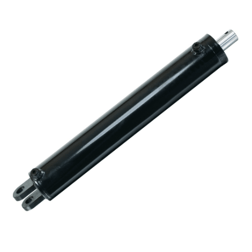
Log Splitters
A log splitter hydraulic pump is the most common application. The wedge advances quickly under low load, then the pump shifts to high pressure to split tough wood. Typical systems use pumps from 11 GPM to 22 GPM, matched to a 4-inch bore cylinder and a 5 to 35-ton splitting force. For equipment builders focused on log splitter systems, our log splitter hydraulic pump selection guide covers GPM, PSI, and engine matching in more detail.
Dump Trailers and Dump Trucks
Scissor-hoist and direct-push dump trailers use two-stage pumps to lift the bed rapidly when empty, then maintain holding force under load. The same principle applies to hydraulic pumps for dump trucks, where fast cycle time and reliable holding pressure are both critical. For more information, please read our article on Dump Trailer Hydraulic Pump.
Hydraulic Presses
Presses need a fast closing stroke followed by a high-force forming or punching phase. A 2 stage hydraulic pump delivers both without requiring an oversized motor running at full pressure throughout the entire cycle.
Compactors
Trash compactors, trench compactors, and vibratory plates use high flow for retraction and feeding, then high pressure for the compaction stroke. The automatic transition keeps cycle times short and energy use reasonable.
Industrial Lifts and Hoists
Lifting equipment moves quickly when lightly loaded, then requires high force for final positioning or for lifting heavy payloads. A two-stage pump supports both operating modes.
Filter Presses
Filter presses fill chambers rapidly with high flow, then require sustained high pressure to dewater the slurry and form a dry cake. Two-stage pumps reduce total cycle time in this batch process.
2 Stage Hydraulic Pump Specifications & Selection Criteria
Selecting the right 2 stage hydraulic pump requires matching the pump’s specifications to the system requirements. The following criteria are the most important. For help matching flow and pressure to your engine, see our hydraulic pump sizing guide.
Flow Rate and Displacement
Nominal flow is usually rated at 3,600 RPM. A 16 GPM pump, for example, may deliver roughly 12 GPM in the high-flow stage and 4 GPM in the high-pressure stage. Check the per-stage displacement, measured in cubic inches per revolution, to confirm the actual flow split.
Pressure Rating and Transition Pressure
Most industrial two-stage gear pumps are rated for 3,000 PSI maximum working pressure. The unload or transition pressure is typically preset near 650 PSI, with an adjustable range of 400 to 900 PSI. Match the transition pressure to the load at which your actuator begins real work.
Shaft, Mounting, and Rotation
Common shaft sizes are 1/2-inch straight keyed shafts, with 4-bolt flange mounting. Verify rotation direction (clockwise or counterclockwise) from the shaft end, and confirm that the pump can operate at your engine’s rated speed.
Port Sizes and Plumbing
Inlet ports are typically larger than outlet ports to prevent suction starvation. A 16 GPM pump may use a 1-inch inlet and a 1/2-inch NPT outlet. Undersized inlet plumbing causes cavitation, noise, and premature wear.
Materials and Fluid Compatibility
Aluminum bodies are common for light and medium-duty. Cast iron center sections or gear housings increase wear resistance in continuous-duty or dirty-oil environments. Confirm compatibility with your hydraulic oil grade and operating temperature range.
Two Stage Hydraulic Gear Pump Manufacturer Specification Comparison
The table below compares common 2 stage hydraulic gear pump specifications from major suppliers.
| Manufacturer / Model | Nominal Flow | Max Pressure | Shaft | Mount | Notes |
|---|---|---|---|---|---|
| Concentric AB 1300483 | 5 GPM @ 3,600 RPM | 3,000 PSI | 1/2″ | 4-bolt | 0.065 / 0.258 in³ displacement |
| Concentric AB 1300484 | 7 GPM @ 3,600 RPM | 3,000 PSI | 1/2″ | 4-bolt | 0.065 / 0.388 in³ displacement |
| Concentric AB 1300485 | 9 GPM @ 3,600 RPM | 3,000 PSI | 1/2″ | 4-bolt | 0.194 / 0.388 in³ displacement |
| Concentric AB 1300487 | 16 GPM @ 3,600 RPM | 3,000 PSI | 1/2″ | 4-bolt | 0.258 / 0.776 in³ displacement |
| Chief 11 GPM | 11 GPM | 3,045 PSI | 1/2″ keyed | 4-bolt | 6 HP input |
| RuggedMade 16 GPM | 16 GPM | 3,000 PSI | 1/2″ × 1.5″ | 4-bolt | Rated for 5-35 ton log splitters |
OEM Sourcing Considerations
For equipment manufacturers and distributors, sourcing two stage hydraulic pumps in volume requires more than catalog matching. Confirm that the supplier can hold the shaft, mounting, and displacement tolerances your power unit requires, and request pressure-test documentation and batch traceability. LOYAL INDUSTRIAL PTE. LTD. supports OEM customers with custom pump configurations, multi-stage quality control, and export-ready packaging for global production lines.
Want a visual breakdown? See our diagram guide to 2 stage hydraulic pumps for a labeled cross-section of the internal flow paths.
How to Size a 2 Stage Hydraulic Pump for Your System

Sizing a 2 stage hydraulic pump involves four calculations: flow rate, pressure, horsepower, and cycle time. The worked example below uses a log splitter because it is the most common application.
Calculate Required Flow Rate
Flow rate determines how fast the cylinder moves. Estimate the volume of oil needed to fill the cylinder bore and stroke, then divide by the desired cycle time.
For a 4-inch bore cylinder with a 24-inch stroke:
- Cylinder area = π × (bore/2)² = π × 2² = 12.57 in²
- Cylinder volume = 12.57 in² × 24 in = 301.6 in³
- Volume in gallons = 301.6 / 231 = 1.31 gallons
To complete the extension in 10 seconds, the required average flow is:
- 1.31 gallons / (10 / 60) minutes = 7.86 GPM
A pump rated near 11 GPM at the high-flow stage provides margin for leakage, hose volume, and valve losses.
Determine System Pressure
Pressure depends on the force required and the cylinder area. For a 25-ton splitting force using the same 4-inch bore cylinder:
- Required force = 25 tons × 2,000 lb/ton = 50,000 lb
- Cylinder area = 12.57 in²
- Pressure = 50,000 lb / 12.57 in² = 3,978 PSI
In practice, system relief valves are set near 3,000 PSI, and the effective splitting force is limited by that setting. A larger bore cylinder or higher pressure rating would be needed to reach 25 tons at 3,000 PSI.
Calculate Engine Horsepower
Hydraulic horsepower is calculated as:
HP = (GPM × PSI) / (1,714 × Efficiency)
For the high-pressure stage of an 11 GPM pump delivering 3.4 GPM at 3,000 PSI with 85% efficiency:
- HP = (3.4 × 3,000) / (1,714 × 0.85) = 7.0 HP
A 6 to 8 HP engine is therefore a reasonable match for this pump. The high-flow stage at 650 PSI uses far less power, so it does not govern engine sizing.
Estimate Cycle Time
Cycle time depends on the effective flow during each phase and the cylinder volume. With an 11 GPM pump that delivers roughly 10 GPM in high-flow mode and 3.4 GPM in high-pressure mode:
- Fast approach volume (to load): approximately 0.9 gallons
- High-flow time: 0.9 / (10/60) = 5.4 seconds
- Work stroke volume: approximately 0.4 gallons
- High-pressure time: 0.4 / (3.4/60) = 7.1 seconds
- Total extension cycle: approximately 12 to 13 seconds
This matches the real-world cycle times reported by builders using 11 GPM two-stage pumps with 4×24 cylinders.
Worked Example — Log Splitter Sizing
Consider a builder selecting a pump for a 22-ton log splitter with a 4-inch bore, 24-inch stroke cylinder and a 6.5 HP engine.
- Engine limit: 6.5 HP
- Maximum pressure: 3,000 PSI
- Available high-pressure flow: (6.5 × 1,714 × 0.85) / 3,000 = 3.16 GPM
An 11 GPM two-stage pump with a 3.4 GPM second stage slightly exceeds the engine’s continuous capability at full pressure. The builder could choose the 11 GPM pump if peak pressure is reached only briefly, or step down to a pump with a smaller second stage for continuous heavy use.
Installation & Maintenance Best Practices
Proper installation and maintenance directly affect how long a 2 stage hydraulic pump lasts. The following practices reduce failure rates and keep cycle times consistent. For a full diagnostic workflow, see our HI/LO hydraulic pump troubleshooting guide.
Mounting Alignment and Coupling
Align the pump shaft with the engine or motor shaft within the manufacturer’s tolerance. Misalignment accelerates bearing wear and can cause seal leaks. Use a flexible coupling where possible, and verify that the pump mounting flange seats flat against the adapter.
Inlet Plumbing and Suction Conditions
Size the inlet lines generously. A restricted inlet causes cavitation, which damages gears and produces noise. Keep the reservoir close to the pump, minimize fittings and bends, and maintain suction line velocity below recommended limits. If the pump is mounted above the reservoir, verify that the static suction head is within the manufacturer’s specification.
Filtration Requirements
Most gear pump manufacturers recommend 25-micron filtration on the return line or pressure line. Contamination is one of the leading causes of gear pump wear. Install and maintain filters according to the duty cycle and ambient conditions.
Fluid Selection and Change Intervals
Use hydraulic oil with the viscosity grade recommended for the operating temperature range. Check fluid level regularly and change oil based on operating hours or contamination analysis rather than a fixed calendar interval. Dark oil, metallic particles, or increased operating temperature are signs that fluid needs attention.
Scheduled Inspection Points
Inspect these items at regular intervals:
- Shaft seal for leaks
- Mounting bolts for looseness
- Inlet hose for collapse or cracking
- Filter condition and pressure drop
- Unloader valve function and setting
- Relief valve setting and leakage
For a complete maintenance schedule, see our 2 stage hydraulic pump maintenance guide.
Troubleshooting Common 2 Stage Pump Problems

When a 2 stage hydraulic pump underperforms, the symptoms usually point to one of a few root causes. Use the table below to narrow the diagnosis. If you need to make some adjustments, you can read our article on 2 Stage Hydraulic Pump Adjustment.
| Symptom | Likely Cause | Initial Check |
|---|---|---|
| Pump fails to build pressure | Worn gears, relief valve stuck open, air in system | Check relief valve setting, bleed air, inspect for internal leakage |
| Pump stays in high-flow mode | Unloader valve stuck or set too high | Verify unload pressure, inspect unloader valve spring and seat |
| Slow cycle time | Engine undersized, worn pump, restricted inlet | Confirm horsepower, check inlet plumbing, measure flow |
| Overheating | Excessive relief valve leakage, undersized reservoir, wrong oil | Check relief valve, verify reservoir size and oil grade |
| Cavitation noise | Restricted inlet, air leak, low fluid level | Inspect inlet hose and fittings, check reservoir level |
| Relief valve chatter | Valve seat damage, contamination, incorrect setting | Clean or replace valve, confirm pressure setting |
Frequently Asked Questions
What is a 2 stage hydraulic pump?
A 2 stage hydraulic pump is a single pump housing that contains two pumping sections: a high-flow/low-pressure stage for fast actuator movement and a low-flow/high-pressure stage for force-intensive work. An internal unloader valve switches between the two stages automatically based on system pressure.
How does a 2 stage hydraulic pump work?
The pump starts in high-flow mode to move the actuator quickly. When resistance rises and system pressure reaches the unload setting, the unloader valve diverts the high-flow stage back to the reservoir. The smaller high-pressure stage then takes over and delivers the force needed for the work phase.
What is a 2 stage hydraulic pump used for?
Common applications include log splitters, dump trailers, dump trucks, hydraulic presses, compactors, industrial lifts, and filter presses. Any machine that needs a fast stroke followed by a high-force work phase can benefit from a two-stage pump.
Can a 2 stage hydraulic pump be repaired?
Yes. Gear-type two-stage pumps can often be rebuilt by replacing worn gears, seals, bearings, and valves. However, integrated units with damaged housings or severely worn chambers may be more cost-effective to replace. Regular maintenance extends service life and reduces the need for major repairs.
How do I size a 2 stage hydraulic pump?
Calculate the cylinder volume and required cycle time to find flow rate, then determine the maximum system pressure from the force requirement. Use the formula HP = (GPM × PSI) / (1,714 × Efficiency) to match the prime mover. Finally, confirm that the pump’s shaft, mounting, and rotation match your power unit.
What is the difference between a single-stage and a two-stage hydraulic pump?
A single-stage pump has one fixed displacement and one flow/pressure curve. A two-stage pump has two discrete operating modes: high flow at low pressure and low flow at high pressure. Two-stage pumps are more efficient for cyclic speed-then-force applications.
What pressure does a 2 stage hydraulic pump switch at?
Most industrial two-stage gear pumps switch from high-flow to high-pressure mode at a factory preset of approximately 650 PSI. Adjustable models typically allow settings from 400 to 900 PSI. Match the switch point to the load at which your actuator begins real work.
How much horsepower does a 2 stage hydraulic pump need?
Horsepower depends on the high-pressure flow and maximum pressure. A pump delivering 3.4 GPM at 3,000 PSI with 85% efficiency requires about 7 HP. The high-flow stage at low pressure uses far less power and does not govern engine sizing.
What filtration does a 2 stage hydraulic pump need?
Most manufacturers recommend 25-micron filtration. Maintaining clean hydraulic fluid is essential for long gear life and reliable unloader valve operation.
Is a 2 stage hydraulic pump the same as a variable-displacement pump?
No. A two-stage pump switches between two fixed operating modes. A variable-displacement piston pump continuously adjusts flow and pressure. Two-stage pumps are simpler, more rugged, and less expensive; variable-displacement pumps offer finer control for continuous heavy-duty systems.
Conclusion
A 2 stage hydraulic pump solves one of the most common problems in mobile and industrial hydraulics: the need for both speed and force from a compact, cost-effective power unit. By automatically switching between a high-flow/low-pressure stage and a low-flow/high-pressure stage, it shortens cycle times, reduces power consumption, and simplifies system design.
The key takeaways from this guide are:
- Choose a 2 stage hydraulic pump for cyclic applications like log splitters, dump trailers, presses, and compactors.
- Size the pump by matching flow rate, pressure, horsepower, and cycle time to your cylinder and load.
- Specify the correct transition pressure, shaft, mounting, and port sizes for your power unit.
- Maintain clean hydraulic fluid, correct inlet plumbing, and perform regular inspections to extend pump life.
For technical specifications, custom sizing support, or OEM sourcing of 2 stage hydraulic pumps, contact LOYAL INDUSTRIAL PTE. LTD.. Our engineering team can help you select the right pump configuration for your equipment and production requirements.