A hydraulic press that takes twelve seconds to complete a stroke, the manufacturer promised in four. A log splitter that stalls every time the wedge meets a knot. A mobile crane whose pump runs hot before the first job is finished. In every case, the buyer spent money on a pump that was technically working but was wrong for the system.
This is why a hydraulic pump sizing guide matters.
Sizing a hydraulic pump isn’t about picking the largest unit in the catalog. It’s about matching flow, pressure, and power to the actual work the machine must perform. This hydraulic pump sizing guide will help you get it right. Working with reliable hydraulic pump suppliers ensures the pump you specify is the pump you receive. Get it right and the system runs efficiently, stays cool, and lasts longer. Get it wrong and you’ll waste energy, generate excess heat, and shorten the life of every component downstream.
In this hydraulic pump sizing guide, you’ll learn a repeatable workflow for hydraulic pump sizing calculation. We’ll cover hydraulic pump GPM calculation, hydraulic pump motor sizing, and the hydraulic pump selection criteria that separate a proper specification from a guess. You’ll also see two worked examples, one in imperial units and one in metric.
What Does Sizing a Hydraulic Pump Mean?

How to size a hydraulic pump comes down to three numbers:
- Flow rate (GPM or L/min): how much oil the pump must move to achieve the required actuator speed
- Pressure (PSI or bar): the force the system must generate to do the work
- Power (HP or kW): the mechanical energy the prime mover must supply to deliver that flow at that pressure
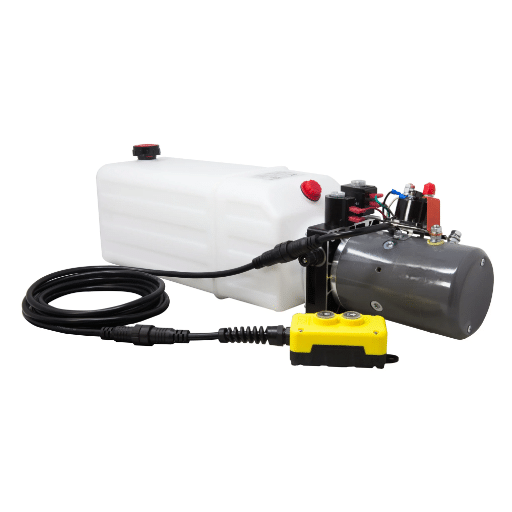
A correctly sized pump delivers enough flow for the fastest cycle, enough pressure for the heaviest load, and does both without forcing the motor to work beyond its rating. The pump, motor, reservoir, and cooling system must be sized as a set. If you change one without checking the others, you’re asking for a field failure. For more information, please read our article on Dump Trailer Hydraulic Pump.
Mini-story: An equipment manufacturer named Elena specified a 5 HP motor for a small press because that was the standard package on the previous machine. The new press needed 12 GPM at 2,000 PSI. The real requirement was closer to 14 HP.
The motor overheated on the first production run, the thermal overload tripped, and the customer rejected the shipment. A simple hydraulic pump motor sizing check would have caught the mismatch in minutes.
The Three Inputs You Need Before Sizing
Before opening a pump catalog, collect these inputs. They are the foundation of every hydraulic pump sizing guide calculation:
- Required actuator force or torque. What is the heaviest load the cylinder or motor must move?
- Required speed or cycle time: How fast must the actuator move under load?
- Available system pressure and drive speed, what pressure is realistic for the application, and at what RPM will the pump run?
If you don’t know these three values, you’re not ready to size the pump. Estimating based on a similar machine can work as a starting point, but it should never replace calculation. Machines that look similar can have very different duty cycles. Need more information about the 2 Stage Hydraulic Pump? You can read our 2 Stage Hydraulic Pump Complete Guide.
Step 1: Calculate Required Flow Rate
Flow rate determines actuator speed. For a cylinder, the relationship is simple: oil volume divided by time. In this step of the hydraulic pump sizing guide, the challenge is using the correct area and units.
Cylinder Extend Flow
The extended area of a cylinder is the full bore area:
A = π × D² / 4Where:
- A = area
- D = bore diameter
The required flow is:
Q = A × vIn imperial units:
GPM = (Area in in² × Velocity in in/s × 60) / 231In metric units:
L/min = (Area in cm² × Velocity in cm/s × 60) / 1000Cylinder Retract Flow
Retract uses the annular area, which is the bore area minus the rod area:
A_retract = π × (D² - d²) / 4Where:
- d = rod diameter
Because the annular area is smaller, the cylinder retracts faster than it extends for the same flow. Always check both directions. If retract speed is critical, size the flow for retract, not extend.
Rotary Actuator / Motor Flow
For a hydraulic motor, use displacement per revolution and required speed:
GPM = (Displacement in in³/rev × RPM) / 231
L/min = (Displacement in cm³/rev × RPM) / 1000
This is also the basis for hydraulic pump GPM calculation when working backward from motor requirements.
Mini-story: A maintenance team replaced a cylinder on a conveyor lift without checking rod diameter. The original cylinder had a 2-inch bore and 1-inch rod. The replacement had a 2-inch bore and 1.25-inch rod. The retract speed increased by nearly 30%.
Loads began overshooting their stop position, and the customer blamed the pump. The pump was sized correctly; the cylinder rod was not.
Step 2: Determine System Pressure Requirement
Pressure creates force. The fundamental relationship is:
F = P × ATo find the required pressure in the cylinder:
P = F / AUse the same units consistently. In imperial units, force is in pounds and area is in square inches, so pressure is in PSI. In metric units, force is in Newtons and area is in square millimeters, so pressure is in MPa; or force in kN and area in cm² gives bar.
This calculation gives the pressure at the actuator, not at the pump outlet. You must add pressure losses between the pump and the actuator:
- Line losses from hose and pipe friction
- Valve losses from directional, flow, and relief valves
- Filter losses which increase as the element loads with contamination
- Elevation head if the cylinder is significantly above or below the pump
A practical starting point is to add 10–15% to the calculated actuator pressure. For long lines or complex valve stacks, a higher margin may be needed. If you need help estimating system losses for a specific layout, contact our engineering team for a detailed review.
Step 3: Size Pump Displacement
Once you know the required flow and the pump drive speed, you can calculate the required displacement:
Displacement in in³/rev = (231 × GPM) / (RPM × ηv)
Displacement in cm³/rev = (1000 × L/min) / (RPM × ηv)
Where:
- ηv = volumetric efficiency, typically 0.85 to 0.95 depending on pump type and condition
Volumetric efficiency accounts for internal leakage. A new piston pump might run at 0.95. A worn gear pump on hot oil might run closer to 0.80. Always use a realistic efficiency, not the theoretical maximum.
Select the next standard displacement size above your calculated value. Catalog displacements are fixed increments, and rounding down guarantees the actuator will not meet its speed target.
Step 4: Hydraulic Pump Motor Sizing Guide
Flow, pressure, and displacement tell you what the pump must deliver. The next step in this hydraulic pump sizing guide is to match that demand to a motor that won’t overheat under load.
Hydraulic power is the product of flow and pressure. The standard formulas are:
Hydraulic HP = (GPM × PSI) / 1714
Metric kW = (L/min × bar) / 600
These give the hydraulic output power. To find the motor input power, divide by the overall efficiency:
Motor HP = (GPM × PSI) / (1714 × ηo)
Motor kW = (L/min × bar) / (600 × ηo)
Where:
- ηo = overall efficiency, typically 0.80 to 0.90
After calculating the required motor power, apply a service factor of about 1.15. Then select the next standard motor size. Standard NEMA motors are available in sizes such as 5, 7.5, 10, 15, 20, 25, 30, 40, 50, 60, 75, and 100 HP.
| GPM | PSI | Efficiency | Required HP | Recommended Motor |
|---|---|---|---|---|
| 10 | 1,500 | 85% | 10.3 | 15 HP |
| 15 | 2,000 | 85% | 20.6 | 25 HP |
| 20 | 2,500 | 87% | 33.5 | 40 HP |
| 25 | 3,000 | 88% | 49.6 | 50 HP |
| 30 | 1,500 | 85% | 30.9 | 40 HP |
This table gives you a quick reference for hydraulic pump motor sizing during early specification work. Always confirm the final selection against the pump manufacturer’s published power curve. If you need a more detailed comparison of the Two Stage Hydraulic Pump vs the Single Stage, you can read our article on Two Stage Hydraulic Pump vs Single Stage.
Mini-story: A distributor named Rahul quoted a customer a 25 HP power unit for a baling press. The customer asked if a 20 HP motor would work to save money. Rahul ran the numbers and found the 20 HP motor would run at 95% load continuously.
That leaves almost no margin for voltage fluctuation, heat, or wear. He recommended the 25 HP unit and documented the calculation. The customer accepted the larger motor, and the press has run without thermal issues for three years.
Step 5: Select the Right Pump Type
Flow, pressure, and power tell you what the pump must do. The application tells you which pump type is best.
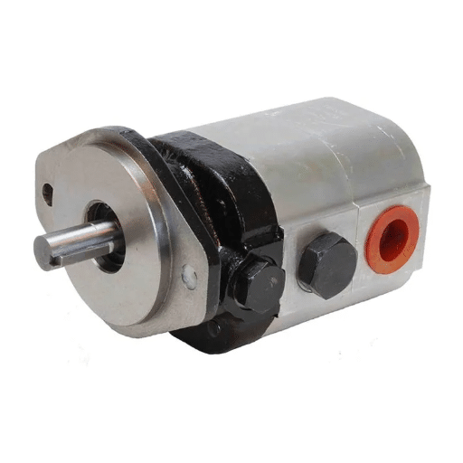
Gear Pumps
Gear pumps are simple, durable, and cost-effective. They work well for fixed-displacement applications at low to medium pressure, typically up to 2,500 PSI. Common uses include log splitters, small presses, and basic power units.
- Typical volumetric efficiency: 80–90%
- Best for: Fixed flow, continuous duty, budget-sensitive systems
- Limitations: Less efficient at high pressure; noise increases with wear
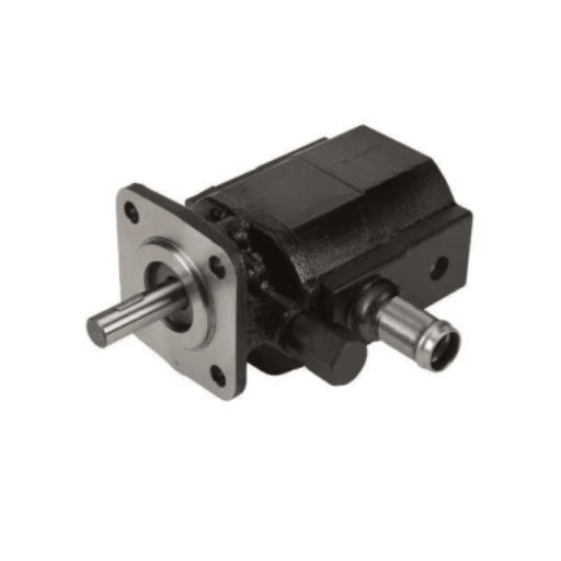
Vane Pumps
Vane pumps offer smoother flow and better efficiency than gear pumps at medium pressure. They are often used in industrial machinery, injection molding, and machine tools.
- Typical volumetric efficiency: 85–95%
- Best for: Medium pressure, low noise, steady flow
- Limitations: More sensitive to contamination than gear pumps
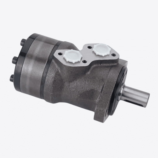
Piston Pumps
Piston pumps are the choice for high-pressure, high-efficiency, and variable-displacement applications. They dominate mobile equipment, construction machinery, and large industrial systems.
- Typical volumetric efficiency: 90–98%
- Best for: High pressure, variable flow, closed-loop systems
- Limitations: Higher cost and stricter cleanliness requirements
| Pump Type | Typical Pressure Range | Typical Efficiency | Best Application |
|---|---|---|---|
| Gear | Up to 2,500 PSI | 80–90% | Log splitters, small power units |
| Vane | Up to 3,000 PSI | 85–95% | Industrial machinery, machine tools |
| Piston | Up to 6,000+ PSI | 90–98% | Mobile equipment, high-pressure systems |
Step 6: Account for System Losses and Efficiency
Real systems aren’t 100% efficient. There are three efficiencies to consider:
- Volumetric efficiency measures how much of the theoretical flow actually reaches the actuator. Losses come from internal leakage and fluid compression.
- Mechanical efficiency measures how much of the input mechanical power is converted to hydraulic power before leakage. Losses come from friction and turbulence.
- Overall efficiency is the product of volumetric and mechanical efficiency. It’s what you use when sizing the motor.
ηo = ηv × ηmTypical overall efficiency ranges:
- Gear pumps: 75–85%
- Vane pumps: 80–90%
- Piston pumps: 85–95%
Using the wrong efficiency is one of the fastest ways to undersize a motor. A pump that looks correct on paper may need 15–20% more input power than a naive calculation suggests. The pump, motor, reservoir, and cooling system must be sized as a set. Understanding how all hydraulic system components work together helps you avoid field failures caused by mismatched specifications.
Step 7: Check Inlet Conditions and Avoid Cavitation
Even a perfectly sized pump will fail if it cannot get enough oil at the inlet. Cavitation occurs when the pressure at the pump inlet drops below the vapor pressure of the fluid. Bubbles form, then collapse inside the pump. The result is noise, erosion, and rapid wear.
Key factors that affect inlet conditions:
- Suction line diameter: Undersized lines create high velocity and low pressure
- Suction line length: Long lines increase friction losses
- Fluid temperature: Hot oil has a higher vapor pressure
- Inlet strainer: A clogged strainer can starve the pump
- Reservoir height: Mounting the pump above the reservoir reduces available inlet pressure
A common rule of thumb is to size the suction line one size larger than the pressure line. Keep suction lines as short and straight as possible. Avoid fittings and valves on the suction side unless they’re necessary.
If your system will operate at high temperature or high altitude, account for reduced atmospheric pressure and increased vapor pressure. These conditions reduce the margin against cavitation.
Common Hydraulic Pump Sizing Mistakes to Avoid

Even experienced engineers make these hydraulic pump sizing mistakes. Avoiding them saves time, money, and field failures.
Oversizing the Pump
Bigger is not always better. An oversized pump produces more flow than the system needs. The excess flow is throttled or bypassed across relief valves, which convert useful power into heat. Oversizing also increases cost, noise, and wear.
Undersizing the Pump or Motor
An undersized pump cannot deliver the required cycle time. An undersized motor overheats and trips overloads. Undersizing is usually the result of ignoring efficiency losses or using theoretical values instead of real-world values.
Ignoring System Losses
Pressure at the pump outlet is not pressure at the actuator. Fittings, hoses, valves, and filters all create a pressure drop. Ignoring these losses leads to insufficient force at the point where work is done.
Using the Wrong Fluid Viscosity
Fluid viscosity changes with temperature. Oil that is too thick at startup increases pressure drop and cavitation risk. Oil that is too thin at operating temperature increases internal leakage and reduces efficiency. Always select hydraulic fluid for the full operating temperature range.
Undersizing the Reservoir
The reservoir is not just an oil tank. It cools the fluid, allows air to escape, and provides reserve volume. A common guideline is a reservoir volume of at least three times the pump flow rate in L/min. Undersized reservoirs lead to overheating and foam.
For equipment builders focused on log splitter systems, our log splitter hydraulic pump selection guide covers GPM, PSI, and engine matching in more detail.
Hydraulic Pump Sizing Calculation: Complete Worked Examples
The best way to learn hydraulic pump sizing calculation is to work through real numbers. The following examples walk through a log splitter in imperial units and an industrial press in metric units.
Requirements:
- Required force: 25,000 lbf
- Bore diameter: 4 in
- Rod diameter: 2 in
- Extend speed: 6 in/s
- System pressure available: 3,000 PSI
- Pump speed: 3,600 RPM
Step A: Pressure check
A = π × 4² / 4 = 12.57 in²
P = 25,000 / 12.57 = 1,989 PSI
Add 10% for losses: 1,989 × 1.10 = 2,188 PSI. The 3,000 PSI system is adequate.
Step B: Required extended flow
GPM = (12.57 × 6 × 60) / 231 = 19.6 GPMRound up to 20 GPM.
Step C: Pump displacement
Assume 90% volumetric efficiency:
Displacement = (231 × 20) / (3600 × 0.90) = 1.43 in³/revSelect a pump with at least 1.5 in³/rev displacement.
Step D: Motor sizing
Assume 85% overall efficiency:
Motor HP = (20 × 3000) / (1714 × 0.85) = 41.1 HPApply 1.15 service factor: 41.1 × 1.15 = 47.3 HP. Select a 50 HP motor.
Example 2: Industrial Press Cylinder (Metric)
Requirements:
- Required force: 200 kN
- Bore diameter: 125 mm
- Extend speed: 0.1 m/s
- System pressure available: 210 bar
- Pump speed: 1,500 RPM
Step A: Pressure check
A = π × 125² / 4 = 12,272 mm² = 122.72 cm²
P = 200,000 N / 12,272 mm² = 16.3 MPa = 163 bar
Add 10% for losses: 163 × 1.10 = 179 bar. The 210 bar system is adequate.
Step B: Required extend flow
L/min = (122.72 cm² × 10 cm/s × 60) / 1000 = 73.6 L/minRound up to 75 L/min.
Step C: Pump displacement
Assume 92% volumetric efficiency:
Displacement = (1000 × 75) / (1500 × 0.92) = 54.3 cm³/revSelect a pump with at least 56 cm³/rev displacement.
Step D: Motor sizing
Assume 88% overall efficiency:
Motor kW = (75 × 210) / (600 × 0.88) = 29.8 kWApply 1.15 service factor: 29.8 × 1.15 = 34.3 kW. Select a 37 kW motor.
Hydraulic Pump Selection Criteria Checklist

Use this hydraulic pump sizing guide checklist before finalizing a pump specification:
- Required actuator force and speed are documented
- System pressure is calculated at the actuator, not the pump
- Pressure losses from lines, valves, filters, and elevation are included
- Required flow is calculated for both extend and retract directions
- Pump displacement is sized with realistic volumetric efficiency
- Motor or engine is sized with overall efficiency and service factor
- Pump type matches pressure, efficiency, and application requirements
- Suction line is sized to avoid cavitation
- Reservoir volume is at least 3× pump flow in L/min
- Fluid viscosity is suitable for the operating temperature range
- Relief valve is set above working pressure but below component ratings
- Cooling system is adequate for expected heat load
If you need a pump specification reviewed or a custom hydraulic solution for your machinery, contact LOYAL INDUSTRIAL PTE. LTD. for engineering support.
Frequently Asked Questions About Hydraulic Pump Sizing
What is hydraulic pump sizing?
Hydraulic pump sizing is the process of selecting a pump that delivers the required flow rate, pressure, and power for a specific application. It ensures the pump can move actuators at the right speed while keeping the motor within its rated capacity.
How do you calculate hydraulic pump GPM?
Calculate GPM by multiplying the actuator area by its velocity and converting to gallons per minute. For a cylinder, use GPM = (Area in in² × Velocity in in/s × 60) / 231.
What size motor do I need for my hydraulic pump?
Size the motor using Motor HP = (GPM × PSI) / (1714 × overall efficiency). Then apply a 1.15 service factor and select the next standard motor size.
How do you size a hydraulic pump for a cylinder?
First, calculate the cylinder bore area and required force to find the pressure. Then determine the flow needed for the desired extend and retract speeds. Finally, size, pump displacement and motor power to match.
What happens if a hydraulic pump is oversized?
An oversized pump wastes energy, generates excess heat, increases noise, and causes unnecessary wear. The excess flow is typically throttled or bypassed, which converts useful hydraulic power into heat.
Conclusion
A reliable hydraulic system starts with correct pump sizing. This hydraulic pump sizing guide has shown you how to move from actuator requirements to a complete specification: flow rate, pressure, displacement, motor power, pump type, inlet conditions, and reservoir sizing. The key is to treat the pump, motor, and fluid system as one integrated design rather than separate parts.
The most common failures don’t come from bad components. They come from components that were never matched to each other. Whether you’re specifying a new machine or troubleshooting an existing one, start with the numbers. Measure the load, time the cycle, check the pressure, and calculate the power.
For replacement pumps, OEM customization, or a full hydraulic system recommendation, contact LOYAL INDUSTRIAL PTE. LTD. today.