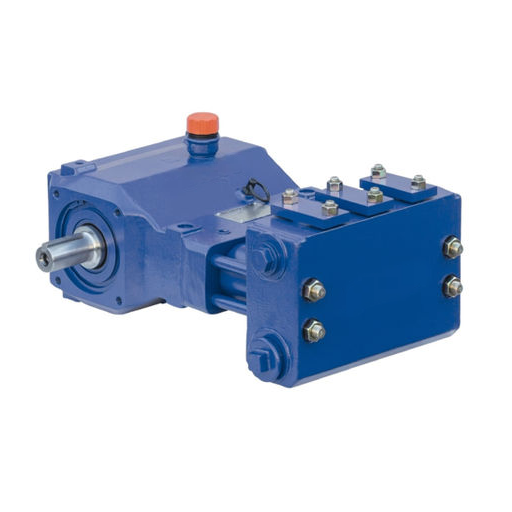
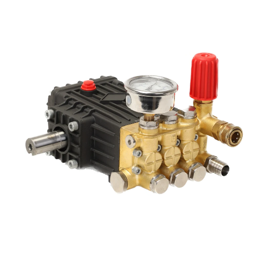
Marta maintains a plant with a dozen hydraulic power units. Last month she ordered a “bigger” gear pump for a clamp circuit that seemed slow, choosing the next frame size up by feel. The machine got faster, briefly. Then the oil ran hot, the relief valve cracked open constantly, and the motor began tripping on thermal overload.
The pump was not the problem. The sizing was.
A hydraulic gear pump looks simple, and that is exactly why it gets mis-specified. Two gears, one housing, a shaft. But behind that simplicity sit four numbers you must get right together: required flow, system pressure, displacement, and drive power.
This guide shows you how to size a hydraulic gear pump step by step, with formulas and worked examples in both US and metric units. By the end, you will be able to convert a circuit’s demand into a real pump size group and a motor that lives a long, easy life.
If you only need the family overview first, our complete guide to hydraulic gear pumps explains external and internal designs, specifications, and applications.
What Sizing a Hydraulic Gear Pump Actually Means

Sizing a hydraulic gear pump means matching the pump’s displacement, pressure rating, speed window, and required drive power to the circuit that will use it. A gear pump is a fixed-displacement, positive displacement machine. Every revolution it moves a nearly constant volume of fluid, so output flow rises and falls with shaft speed. There is no internal adjustment that changes the swept volume.
That last point shapes every decision in this article. Because a gear pump is fixed displacement, you do not choose a gear pump by turning a dial. You choose the displacement that delivers the flow your actuators need at the speed your drive provides, then you confirm the pump can carry the pressure continuously, and finally you size the prime mover.
One concept removes most of the confusion: the pump creates flow, not pressure. Pressure is built by the load downstream. A cylinder pushing against a heavy object, or a motor driving a heavy winch, resists the flow, and that resistance appears as pressure. So flow comes first, then pressure is checked against the pump’s rating.
There are four numbers to fix, in order:
- Required flow (GPM or L/min), set by your cylinders and motors.
- Required displacement (in³/rev or cc/rev), flow divided by drive speed.
- Pressure rating (PSI or bar), must cover the maximum continuous system pressure.
- Required drive power (HP or kW), flow and pressure converted into motor or engine size.
For a direct comparison of gear and vane economics, see our gear pump vs vane pump guide.
Step 1: Find the Flow Your Circuit Needs
Flow is the volume of oil a cylinder or hydraulic motor must consume each minute to move at the speed you want. Work backward from the actuator. A cylinder needs more flow to extend faster; a motor needs more flow to spin faster.
For a cylinder, flow depends on bore area and stroke speed. In US units:
Flow (GPM) = (Cylinder area in² × Stroke speed in/sec × 60) / 231
In metric:
Flow (L/min) = (Cylinder area cm² × Stroke speed m/min) / 10
For a hydraulic motor, required flow comes from the motor’s displacement and target speed:
Flow (GPM) = (Motor displacement in³/rev × Motor RPM) / 231
Flow (L/min) = (Motor displacement cc/rev × Motor RPM) / 1,000
Retract strokes matter too. A single-rod cylinder retracts faster than it extends at the same flow, because the rod takes up volume on the rod side. If your cycle time is governed by the retract stroke, size for the larger of the two flows, not the average.
Mini-example: A clamp cylinder with a 3-inch bore must extend at 4 in/sec. Area = π × 1.5² ≈ 7.07 in². Flow = 7.07 × 4 × 60 / 231 ≈ 7.3 GPM. That is the flow the pump must deliver at full stroke.
If the actuator sizing itself is new to you, our general hydraulic pump sizing guide covers cylinders, motors, and reservoir sizing across all pump types. This guide stays focused on the gear pump family.
Step 2: Size the Gear Pump Displacement (cc/rev or in³/rev)

Once you know the required flow, convert it to displacement. Displacement is the volume a pump moves per revolution, stated in cubic centimeters per revolution (cc/rev) or cubic inches per revolution (in³/rev). It is the number on the nameplate that tells you the pump’s size.
US: Displacement (in³/rev) = Required flow (GPM) × 231 / Pump speed (RPM)
Metric: Displacement (cc/rev) = Required flow (L/min) × 1,000 / Pump speed (RPM)
The 231 is the number of cubic inches in one US gallon. The 1,000 converts liters to cubic centimeters.
Drive speed is usually fixed before you size the pump. An electric motor turns at a set speed, commonly 1,450 RPM on 50 Hz or 1,750 RPM on 60 Hz. An engine PTO might deliver 1,800 to 2,200 RPM. Because you cannot change the motor speed easily, the displacement is the variable you solve for.
Account for Volumetric Efficiency (Slip)
Theoretical displacement assumes no leakage. In reality, a small amount of oil slips backward through the clearances between the gear tips, gear faces, and housing every revolution. This internal leakage is called slip, and it means actual flow is lower than theoretical flow.
Gear pump volumetric efficiency typically runs 85 to 95 percent. Higher-viscosity fluid seals the clearances better and gives the high end of the range; thin, hot fluid and high pressure push you toward the low end. A well-built gear pump at moderate pressure often sits near 90 percent.
To deliver your target flow under load, divide the required flow by the expected volumetric efficiency:
Displacement (cc/rev) = Required flow (L/min) × 1,000 / (RPM × ηv)
where ηv is volumetric efficiency as a decimal, such as 0.90.
Mini-example: You need 40 L/min delivered at working pressure, driven at 1,450 RPM, expecting 90% volumetric efficiency. Displacement = 40 × 1,000 / (1,450 × 0.90) = 30.7 cc/rev. The nearest standard frame is roughly 30 to 32 cc/rev.
Land on a Real Pump Size Group
You do not buy displacement to three decimals. Gear pump manufacturers build standard size groups, commonly called Group 1, Group 2, and Group 3 frames, each spanning a displacement range with matching mounting, shaft, and port dimensions.
| Size group | Typical displacement | Typical flow @ 1,450 RPM | Typical flow @ 1,800 RPM |
|---|---|---|---|
| Group 1 | 1–12 cc/rev (0.06–0.73 in³/rev) | 1.5–17 L/min | 2–22 L/min |
| Group 2 | 12–50 cc/rev (0.73–3.1 in³/rev) | 17–73 L/min | 22–90 L/min |
| Group 3 | 50–125+ cc/rev (3.1–7.6+ in³/rev) | 73–180+ L/min | 90–225+ L/min |
The table above is a guide, not a substitute for a manufacturer’s catalog. After you calculate a required displacement, round up to the nearest standard frame in the appropriate group, then confirm that frame’s mounting, shaft, and port options match your drive and plumbing. For a fuller treatment of the displacement math across pump types, see our hydraulic pump displacement formula explainer.
Step 3: Check Pressure Rating and Understand Derating
Pressure is the second number, and it is where many gear pump selections go wrong. The pump’s continuous pressure rating must cover the maximum system pressure your circuit sees in normal operation, not just the relief valve setting you hope never to reach.
Two rules matter:
Rule 1, Size for continuous pressure, not peak. Gear pumps have a continuous rating, a maximum rating, and sometimes a short peak rating. Continuous is what the pump can hold indefinitely. Maximum is a limit for brief, intermittent spikes. If your circuit runs at 200 bar most of the time with spikes to 230 bar, pick a pump rated for at least 200 bar continuous.
Rule 2, Larger displacement pumps carry less pressure. This is the counter-intuitive one. The pressure difference between inlet and outlet pushes the gears sideways and loads the bearings.
A bigger pump has more gear area for that pressure to act on, so manufacturers derate maximum pressure as displacement grows. A small Group 1 external gear pump may be rated at 250 bar continuous, while the largest Group 3 frame in the same series might drop to 130 to 160 bar. Always read the rating for the exact displacement you selected, not the series headline number.
A relief valve is mandatory on a gear pump circuit. Because a gear pump is positive displacement, it keeps pushing fluid even against a blocked line, and pressure rises until something fails. Set the relief valve below the pump’s maximum rating to protect both the pump and the rest of the circuit.
For more information, please read our article on tandem gear pumps.
Step 4: Check Speed and Inlet Conditions
A correctly sized displacement is worthless if the pump cannot be fed. Gear pumps have a recommended speed window, and they are far less forgiving of a starved inlet than a piston pump.
Speed. Every series lists a rated speed range. Running too slowly means the tooth spaces do not fill completely and slip rises. Running too fast, especially at high pressure, increases wear and heat. Confirm your drive speed falls inside the pump’s rated window. If your engine turns 2,200 RPM and the pump is rated to 2,500 RPM, you are fine; if it is rated to 2,000, you need a speed reducer or a different pump.
Inlet conditions. A gear pump is self-priming to a degree, but its suction is weak. The safest arrangement is a flooded inlet, with the reservoir level above the pump inlet so oil gravity-flows in. Keep suction-line velocity low, around 1.2 m/s (4 ft/s), and outlet velocity under about 4.5 m/s (15 ft/s), guidance that pump service manuals spell out. Long suction lines, a clogged strainer, or undersized suction piping invite cavitation, which sounds like gravel in the pump and erodes it from the inside.
Viscosity and cold start. Fluid viscosity drives both speed limit and slip. Thick oil at cold start resists being drawn into the pump and raises power demand; thin oil at running temperature slips more. If the machine starts cold in winter, confirm the pump can be turned at starting viscosity, and expect a temporary drop in output until the oil warms. When you size the pump, use the operating viscosity of your fluid, then sanity-check the cold-start case.
For a detailed look at the single-gear-pair design behind most industrial and mobile circuits, see our guide to the external gear pump.
Step 5: Size the Drive (Motor or Engine)

With flow, displacement, and pressure fixed, the last number is drive power. This is where the “1 HP per GPM at 1,500 PSI” rule of thumb that circulates on equipment forums comes from. It is a useful memory aid: at 1,500 PSI, one horsepower drives roughly one GPM. At 3,000 PSI, the same GPM needs about twice the power. For a precise figure, use the standard hydraulic power formulas:
Hydraulic HP = Flow (GPM) × Pressure (PSI) / 1,714
Hydraulic kW = Flow (L/min) × Pressure (bar) / 600
The 1,714 and 600 constants convert the mixed units into power, and they appear in every hydraulic reference.
Then convert hydraulic power to the shaft power the motor must deliver. A pump converts input shaft power into hydraulic power with an overall efficiency that includes both mechanical losses and volumetric losses:
Input HP = Hydraulic HP / ηoverall
A reasonable overall efficiency assumption for sizing is 85 to 90 percent for a healthy gear pump.
Finally, add a service factor. Running a motor or engine at its exact calculated limit leaves no room for cold oil, wear, or measurement error. Multiply by 1.15 to 1.20 and round up to the next standard motor size.
Think of it as motor longevity, not just safety. An engine or electric motor loafing at 85 percent of its rating runs cooler and lasts far longer than one pinned at 100 percent.
One nuance from the field is worth stating clearly: internal slip does not change the power equation the way many people expect. If you size the displacement for the required flow and include volumetric efficiency, the drive power is computed from the flow the pump moves and the pressure it builds. Do not add extra horsepower simply because the pump “leaks.” Leakage is already accounted for in the displacement and efficiency you chose.
What adds power demand is selecting an oversized displacement in the first place, which is exactly why you size displacement first and power second.
To check a specific number quickly, our hydraulic pump horsepower calculator does the math in seconds.
Worked Examples
The method is easier to trust when you watch it run end to end. Here are two full examples, one in US units for mobile equipment and one in metric units for an industrial power unit.
Example A: Mobile auxiliary circuit (US units)
A compact loader needs an auxiliary attachment circuit. The circuit requires 10 GPM delivered at up to 2,500 PSI, driven from an engine PTO at 1,800 RPM.
Step 1, Flow. Already known: 10 GPM delivered under load.
Step 2, Displacement. Assume 90% volumetric efficiency at working pressure. Theoretical flow needed = 10 / 0.90 = 11.1 GPM. Displacement = 11.1 × 231 / 1,800 = 1.43 in³/rev ≈ 23.4 cc/rev. Select a standard Group 2 frame at 25 cc/rev.
Step 3, Pressure. 2,500 PSI ≈ 172 bar. A Group 2 external gear pump at 25 cc/rev is typically rated 200 to 250 bar continuous, so the duty fits with margin.
Step 4, Speed. 1,800 RPM is comfortably inside the rated window for a Group 2 pump.
Step 5, Drive power. The selected 25 cc/rev pump moves 25 × 1,800 / 1,000 = 45 L/min ≈ 11.9 GPM theoretical. Input hydraulic power = 11.9 × 2,500 / 1,714 ≈ 17.4 HP. With 90% overall efficiency, shaft power ≈ 19.3 HP. Apply a 1.15 service factor: 22.2 HP. Select a 25 HP motor (or a 23–25 HP engine rating).
Example B: Industrial power unit (metric units)
A machine tool power unit must supply 45 L/min delivered at up to 160 bar, driven by a four-pole electric motor at 1,450 RPM.
Step 1, Flow. Known: 45 L/min delivered.
Step 2, Displacement. Assume 90% volumetric efficiency. Theoretical flow = 45 / 0.90 = 50 L/min. Displacement = 50 × 1,000 / 1,450 = 34.5 cc/rev. Select a standard 35 cc/rev frame.
Step 3, Pressure. 160 bar is well within the continuous rating of a 35 cc/rev gear pump.
Step 4, Speed. 1,450 RPM is a standard, safe operating point for this frame.
Step 5, Drive power. The selected 35 cc/rev pump moves 35 × 1,450 / 1,000 = 50.8 L/min theoretically. Input hydraulic power = 50.8 × 160 / 600 ≈ 13.5 kW. With 90% overall efficiency, shaft power ≈ 15.0 kW. Apply a 1.15 service factor: 17.3 kW. Select the next standard motor size, an 18.5 kW IEC frame.
| Example A (US) | Example B (metric) | |
|---|---|---|
| Application | Loader auxiliary circuit | Machine tool power unit |
| Delivered flow | 10 GPM | 45 L/min |
| Max system pressure | 2,500 PSI | 160 bar |
| Drive speed | 1,800 RPM | 1,450 RPM |
| Assumed volumetric efficiency | 90% | 90% |
| Required theoretical flow | 11.1 GPM | 50 L/min |
| Calculated displacement | 23.4 cc/rev | 34.5 cc/rev |
| Selected frame | 25 cc/rev (Group 2) | 35 cc/rev |
| Hydraulic power | 17.4 HP | 13.5 kW |
| Motor (with service factor) | 25 HP | 18.5 kW |
Both examples assume new, healthy pumps at operating temperature. Field conditions, cold oil, worn pumps, and high altitude for engines are exactly what the service factor absorbs.
For an industry-by-industry breakdown with typical equipment and pump specifications, read our gear pump applications article.
Verify Mounting, Shaft, Ports, and Rotation Before You Order

The math can be perfect and the pump still wrong for your machine if the interfaces do not match. Before you place an order, confirm four physical details against the pump drawing:
- Mounting. Gear pumps use standard flanges, most commonly SAE two-bolt or four-bolt and ISO 3019/2 styles. Match the pump flange to the motor bell housing or the engine adapter.
- Shaft. The pump shaft must match the drive coupling, keyed, splined, or tang style, with the correct diameter and length. A keyed shaft from a motor usually needs a coupling; a splined pump shaft needs a matching splined drive.
- Ports and port sizes. Suction and pressure ports come in SAE O-ring, BSPP, NPT, and metric threads. Confirm the thread type and size match your fittings, and confirm the port sizes are adequate for the flow to keep velocities in range.
- Rotation direction. Gear pumps are directional. Clockwise and counter-clockwise versions are built differently, and you cannot simply spin one backward. Check the pump’s rotation against the drive, because a wrong rotation means no flow. Our guide to SAE mounting and port standards walks through these interfaces in detail.
For step-by-step nameplate reading and brand cross-reference guidance, see our gear pump replacement and interchange guide.
If you have settled the flow, pressure, and displacement but are unsure about the interfaces, that is the moment to get engineering input. Our applications engineers at LOYAL INDUSTRIAL PTE. LTD. confirm mounting, shaft, port, and rotation matching as part of selection support, and we supply gear pumps tested to specification across all three size groups.
Common Gear Pump Sizing Mistakes
Watch for these five, because they account for most of the failed circuits we see.
1. Oversizing for speed. Choosing a bigger pump to make a machine faster without raising the drive power leads to a relief-valve dump and a hot, noisy system. More flow than the circuit uses has to go somewhere, and it usually goes over the relief valve as heat. On equipment forums, experienced owners point out that cycle time is rarely the real bottleneck; handling the work often is.
2. Undersizing the drive. The reverse failure: a bigger pump on the same motor. The motor bogs or the engine stalls exactly when the circuit needs peak pressure. Manufacturers publish horsepower requirements for a reason.
3. Ignoring volumetric efficiency. Sizing from theoretical displacement alone leaves the machine slow under load. Always divide by expected volumetric efficiency, and be honest about the pressure and fluid temperature the pump will actually see.
4. Adding horsepower for slip. As noted above, slip is handled by displacement and efficiency. Adding power on top of that is a double count that produces an oversized motor and needless cost.
5. Skipping the derating check. Specifying a big-displacement pump for a high-pressure circuit without checking the frame’s actual continuous rating is a recipe for premature bearing failure. Bigger gears mean lower allowable pressure.
For full maintenance schedules and diagnostic tables, see our hydraulic gear pump maintenance guide.
Frequently Asked Questions
How do you size a hydraulic gear pump?
Sizing a hydraulic gear pump is a five-step process: calculate required flow from your actuators, convert that flow into displacement (cc/rev or in³/rev) at your drive speed, confirm the pressure rating with derating, check speed and inlet conditions, then size the drive power with a service factor.
How do I calculate gear pump displacement?
Divide required flow by pump speed. In US units, displacement (in³/rev) = GPM × 231 / RPM. In metric units, displacement (cc/rev) = L/min × 1,000 / RPM. Divide by volumetric efficiency, typically 0.85 to 0.95, to account for slip.
What is the formula for gear pump flow?
Theoretical flow equals displacement times speed. US: GPM = in³/rev × RPM / 231. Metric: L/min = cc/rev × RPM / 1,000. Actual flow equals theoretical flow multiplied by volumetric efficiency.
What is a good gear pump volumetric efficiency?
Most gear pumps deliver 85 to 95 percent volumetric efficiency. Higher-viscosity fluid and moderate pressure sit near the top of the range; thin, hot fluid and high pressure push efficiency toward the bottom.
How much horsepower do I need to drive a hydraulic gear pump?
Use hydraulic HP = GPM × PSI / 1,714, or kW = L/min × bar / 600. Divide by overall efficiency and multiply by a 1.15 to 1.20 service factor. A common rule of thumb is roughly 1 HP per GPM at 1,500 PSI.
Do bigger gear pumps handle less pressure?
Yes. Larger displacement increases the gear area that discharge pressure acts on, which loads the bearings more heavily. Manufacturers derate maximum continuous pressure as pump size grows, so always check the rating for the exact displacement you selected.
Conclusion
How to size a hydraulic gear pump comes down to a sequence, not a guess. Work through the numbers in order, and each decision supports the next:
- Define the flow your actuators need.
- Convert flow into displacement at your drive speed, with volumetric efficiency included.
- Select a size group and confirm the continuous pressure rating covers your duty, respecting derating.
- Check speed and keep the inlet flooded.
- Size the drive power with a 1.15 to 1.20 service factor.
Done correctly, the pump delivers the flow you designed for, runs inside its ratings, and lets the motor live an easy life. Done by feel, you get the machine Marta inherited: hot oil, a screaming relief valve, and a pump that was never the real problem.
This week, write down your required flow, working pressure, and drive speed before you look at any pump catalog. If you want the selection confirmed against a real frame size and mounting interface, contact LOYAL INDUSTRIAL PTE. LTD. for an engineering consultation. We will help you match a tested hydraulic gear pump to your exact duty and keep your equipment running without interruption.