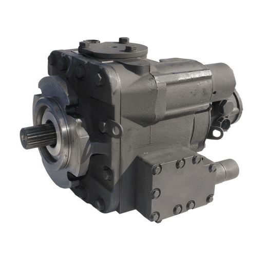
Valerie stopped working on the pump in front of her on the table. It was well used, the model was sticky and unreadable, and the threads on the nozzle were chipped, making it difficult to perform any measurements. The new one had to arrive by this Thursday. Without knowing the type of porting used, whether SAE O-ring boss or JIC 37-degree flare, the male adapter cannot be placed, although the hose assembly will still be incomplete.
A similar instance runs across maintenance workshops on a daily basis. This is due to the fact that the SAE standards have certain specifications which are needed whenever hydraulic equipment is being mounted, and can be used by an operator in the rest of the circuit and at times could be specific to a pump only. Most articles cover only one side, leaving buyers with incomplete specifications and wrong parts on the shelf.
This guide gives you a complete picture of SAE mounting port standards as they apply to hydraulic pumps. You will get the J744 flange dimension table that belongs in your design file, the dash size system that controls port sizing, a field identification method for unknown ports, torque values for assembly, and a procurement checklist you can paste straight into an RFQ.
Want to learn more about the 20 GPM Hydraulic Pump? Please check out our guide about the 20 GPM Hydraulic Pump.
What SAE Standards Govern Hydraulic Pumps

SAE standards cover two separate engineering problems: mechanical mounting and fluid connection. Knowing which standard applies to which problem prevents the specification errors that show up as warranty claims.
SAE J744, Mounting Flanges and Shaft Ends
SAE J744 introduces the provisions for interfacing the flanges of an electric motor, engine, gearbox or equivalent to a pump and their keyway specifics to include the reinforcement cover profiles, cited port, and difference in shaft. When you mate a pump with a motor, J744 is the rule to determine whether the bolt holes of both match.
SAE J1926, O-Ring Boss Ports
SAE J1926 talks about threads of ORB or other O-ring ports – the dominant style of connection on valves. An O-ring is a cylindrical gasket that is placed within the groove of male threads so that it does not exert pressure on the cylindrical male plastic threads when the two faces one another. This is used in most high-pressure systems since it is a connection that can be taken apart anytime and is therefore used for fittings where the pipe diameter is less than 2 inches.
SAE J518, Split Flange Ports
SAE J518 gives the requirements for four-bolt split flange connections which are made for high-flow porting arrangements larger in size. The split flanges could be in any size depending on the requirements and the standard pressure ratings are rated to 3000 PSI for code 61 and 6000 PSI for code 62. Split flanges include a flared tube, which is a branch of the joint pressed against the plain surface of a flat port with any cut-out contours.
SAE J514, JIC 37-Degree Flare
The 37-degree flare that is defined by SAE J514 is typically located in hydraulic settings in the continent of North America. The closure layering comes as a result of the metal-to-metal contact of the male fitting cone with the female fitting flare. JIC 37-degree utilizes ORB UNF threads for most dashes as well, and JIC 37-degree is often mistakenly thought of as ORB.
SAE J1453, ORFS Face Seal
SAE J1453 covers O-ring face seal fittings, which use an O-ring trapped in a groove on the flat face of the male fitting. ORFS is gaining ground in high-vibration applications because the O-ring seal tolerates motion better than metal-to-metal flare joints.
ISO Equivalents
ISO 3019-1, for mounting flanges, is the global version of SAE J744. ISO 6162 with the exception of split flanges, is the internationally acceptable equivalent of SAE J518. ISO 6149 is to metric the major amount of SAE J1926, which is for unported o-ring flanges. This means that in case of the constructions destined for export, the pattern number SAE of the element in question is, together with the ISO one, indicated on the drawing and therefore no conflicts with the classifiers that the customs clearance or procurement offense arises.
Need a pump specified to exact SAE standards? Request a technical specification sheet and our engineers will confirm mounting flange, shaft, and port configuration against your motor or gearbox.
SAE J744 Mounting Flange Standards
The difference of this drawing is the connection device between the pump and the main engine. The disadvantages of the wrong connection device are – the fastening holes do not correspond to each other, nobody can say the fastening part is in the center or the spline of the bushing cracks under the effect of the overpressure.
The Two-Bolt Flange Series
SAE J744 is documented as an expanding scale of size tags attached to a two-bolt toilet flange from AA to F, all relating to a better flow capacity with the high-speed two-bolt flange pumps and developing its torque abilities. The order of the flange nomenclature is simple: AA, the smallest, goes to F, the largest. Most of the industry pumps are designed to use gear pumps with A, B, or C flanges.
The Four-Bolt Flange Series
Also, four bold flanges can be used for larger axial piston pumps as a solution to the problem of weight distribution. The dimensions SAE C, D and E have their bolt circles widened and all three versions can be installed with a four-bolt flange instead of the conventional two-bolt flange.
SAE J744 Dimension Table
Use this table as your quick reference for pilot diameter, bolt circle, and bolt hole size.
| SAE Code | ISO Code | Pilot Diameter (P) | Bolt Circle (K) | Bolt Hole (D) | Typical Pump Size |
|---|---|---|---|---|---|
| AA | 50-2 | 2.00 in (50.8 mm) | 3.25 in (82.6 mm) | 0.406 in (10.3 mm) | <5 cc/rev |
| A | 82-2 | 3.25 in (82.55 mm) | 4.187 in (106.4 mm) | 0.437 in (11.1 mm) | 5–18 cc/rev |
| B | 101-2 | 4.00 in (101.6 mm) | 5.75 in (146 mm) | 0.562 in (14.3 mm) | 20–45 cc/rev |
| C (2-bolt) | 127-2 | 5.00 in (127 mm) | 7.125 in (181 mm) | 0.687 in (17.5 mm) | 50–90 cc/rev |
| C (4-bolt) | 127-4 | 5.00 in (127 mm) | 7.50 in (190.5 mm) | 0.562 in (14.3 mm) | 50–90 cc/rev |
| D (4-bolt) | 152-4 | 6.00 in (152.4 mm) | 9.00 in (228.6 mm) | 0.812 in (20.6 mm) | 100–180 cc/rev |
| E (4-bolt) | 165-4 | 6.50 in (165.1 mm) | 12.50 in (317.5 mm) | 1.062 in (27.0 mm) | 190+ cc/rev |
| F (4-bolt) | 177-4 | 7.00 in (177.8 mm) | 13.781 in (350 mm) | 1.062 in (27.0 mm) | 200+ cc/rev |
Shaft End Options
The SAE J744 also sets down the gauge of the splines as well as the shafts. The splines of the shaft are identified in terms of the numbers of teeth and pitch 9-tooth 16/32 pitch is for SAE A, 13-tooth 16/32 pitch is for SAE B, and 15-tooth 16/32 pitch is for SAE C. Keyway cross-section is performed by the corresponding sizes. When it comes to a spline set, the best option should be to match the number of teeth with the pitch to the primary part the replacement spline was connected to; that is, a 13-tooth spline cannot be used in a 15-tooth adapter.
SAE A vs B vs C, When Each Applies
- SAE A: Small gear pumps and vane pumps up to roughly 18 cc/rev, common on compact mobile equipment and machine tool auxiliaries.
- SAE B: The industrial workhorse. Medium gear pumps, vane pumps, and small piston pumps from 20 to 45 cc/rev. Fits most 5 to 15 HP motors.
- SAE C: Large gear pumps and medium piston pumps from 50 to 90 cc/rev. Requires a correspondingly larger motor frame.
Mini-story: In 2024, a design engineer at a mobile equipment OEM firm in Ohio preferred to use an SAE B mount casting style for a 65 cc/rev pump because the motor inventory contained a set of SAE B adaptors. The pump fit in the housing well but the B-frame had a spline which supported 248 Nm however pump was demanding 340 Nm during peak load. The spline failed on the way to peak load on the first full load test. A torque fit, this time using an SAE C flange that had a 15-tooth spline instead, adjusted the problem, but adding the modifications took three extra weeks to the project timeline. Gearing towards the prevention of the spline disengagement, the choice of the flange should be based on the ability of the splines to provide certain torques, not only how seamless the frame fits.
SAE Port Standards for Hydraulic Pumps

Once the pump is mounted, fluid must enter and exit through ports that match the hose and fitting system. SAE defines three port families that appear on hydraulic pumps.
SAE J1926 O-Ring Boss (ORB)
ORB is the default threaded port on hydraulic pumps. The female port has straight UNF threads and a chamfered seat. The male fitting has matching straight threads and an O-ring seated near the base. When tightened, the O-ring compresses against the chamfer to form a high-pressure seal. ORB is rated for continuous pressures above 5,000 PSI, depending on dash size and is the standard for pump inlet and outlet ports.
SAE J518 Split Flange, Code 61 and Code 62
Split flanges are used on larger ports where threaded connections would require impractically large fittings. The pump body has a flat machined pad with four tapped holes arranged in a rectangular pattern. A flanged head with an O-ring groove bolts to the pad. Two halves of a split flange clamp the flanged head in place. Code 61 is the standard 3,000 PSI series. Code 62 is the high-pressure 6,000 PSI series with a thicker flange head.
SAE J1453 ORFS, O-Ring Face Seal
ORFS uses an O-ring trapped in a groove on the flat face of the male fitting. The fitting threads onto the port, but the seal is made by the O-ring against the flat face of the female port, not by thread engagement. ORFS tolerates vibration better than JIC flare fittings and is increasingly common on mobile equipment where frame flex and shock are present.
SAE J514 JIC 37-Degree, Flare Fitting
JIC 37-degree flare fittings seal metal-to-metal between the cone of the male fitting and the flared seat of the female port or tube end. They are widely used in North American hydraulic systems, but are NOT interchangeable with ORB even though they share the same UNF thread at many dash sizes. The difference is the sealing surface: chamfer for ORB, cone for JIC.
SAE Dash Size System Explained
Dash sizes are the universal shorthand for hydraulic fitting and port sizing. Understanding the system eliminates the guesswork when ordering adapters and hoses.
What Dash Numbers Mean
A dash size is the nominal tube outer diameter in sixteenths of an inch. The formula is simple:
Nominal Tube OD = Dash Number × 1/16 inch
- Dash -4 = 4/16 = 1/4 inch
- Dash -6 = 6/16 = 3/8 inch
- Dash -8 = 8/16 = 1/2 inch
- Dash -10 = 10/16 = 5/8 inch
- Dash -12 = 12/16 = 3/4 inch
- Dash -16 = 16/16 = 1 inch
- Dash -20 = 20/16 = 1-1/4 inch
- Dash -24 = 24/16 = 1-1/2 inch
- Dash -32 = 32/16 = 2 inches
Dash Size to Thread Size Conversion
| Dash Size | Nominal Tube OD | SAE ORB Thread (UNF) | Common Use |
|---|---|---|---|
| -4 | 1/4 in | 7/16″-20 | Gauge ports, small case drains |
| -6 | 3/8 in | 9/16″-18 | Small pump inlets, pilot lines |
| -8 | 1/2 in | 3/4″-16 | Medium pump inlets, return lines |
| -10 | 5/8 in | 7/8″-14 | Medium pump outlets, pressure lines |
| -12 | 3/4 in | 1-1/16″-12 | Standard pump pressure ports |
| -16 | 1 in | 1-5/16″-12 | Large pump ports, high-flow inlets |
| -20 | 1-1/4 in | 1-5/8″-12 | High-flow suction lines |
| -24 | 1-1/2 in | 1-7/8″-12 | Large pump inlets |
| -32 | 2 in | 2-1/2″-12 | Very high-flow applications |
Common Port Size Assignments by Pump Frame
- SAE A pumps: Typically -8 inlet, -6 or -8 outlet
- SAE B pumps: Typically -12 inlet, -10 or -12 outlet
- SAE C pumps: Typically -16 inlet, -12 or -16 outlet
How to Identify Unknown SAE Ports in the Field

Sometimes it is difficult to read the name plate or locate the missing manual. The port can still be identified because we have a thread gauge, a flashlight, and calipers on site.
Step 1: Measure Thread Diameter and Count Threads Per Inch
Sneak a thread pitch gauge into the threaded opening in order to determine threads per inch. For example, for UNF threads, which are commonly used in SAE ports, the dimensions of 12, 14, 16, 18, or 20 threads per inch should be observed. Measure the major diameter with calipers. A 9/16 inch major diameter having a 18 TPI is a -6 ORB or JIC fitting. Whereas, a 1-1/16 inch major diameter with 12 TPIs would be a -12.
Step 2: Check for O-Ring Groove vs Flare Seat
Look with the torch at the internals of the female port. If the port has a counterbore seat for an O-ring at the bottom of the bore, then it would be termed as SAE J1926 ORB. In case the port has a concave 37-degree seat, this is JIC 37-degree flare. When the port is a plain machined pad with only four bolt holes arranged in a rectangular shape, then this is the split flange as per SAE J518.
Step 3: Identify Flange Type
For components with split flange ports, the dimensions that have to be focused on include the resistance to two holes and the width of the port. The flange holes are the same for Code 61 standards and Code 62 requirements, but the thickness of the flange head from the flange face to the O-ring grooves differs. Use the thickest flange which is Code 62 for all systems operating for pressures above 3,000 PSI.
Step 4: Cross-Reference to Dash Size and Standard
With thread diameter, pitch, and port geometry confirmed, cross-reference to the dash size table above. Order adapters and hoses by dash size and standard, not by thread description alone.
Common Look-Alikes That Cause Misidentification
The most expensive mistake in hydraulic maintenance is ordering JIC adapters for ORB ports. At dash sizes -6, -8, and -10, the UNF threads are identical. The only difference is the sealing surface. An ORB fitting in a JIC port will not seal and will leak immediately under pressure.
Mini-story: In late 2024, the maintenance technician at a Georgia jobber operation was fixing a stripped port on an old gear pump with no nameplate. He checked the parameters and determined that it was equivalent to 3/4 inch major diameter and 16 threads per inch, which was or perhaps still is in the dash -8 where it is supposed to be. He ordered a JIC 37-degree adapter because that was what the shop stocked. The adapter threaded in perfectly but leaked at 1,800 PSI. Four hours of downtime later, a second technician noticed the chamfered seat in the port. The correct ORB adapter with an O-ring solved the leak in five minutes. The $12 JIC adapter cost four hours of lost production.
SAE Port Size Selection by Flow and Pressure

Port sizing is not arbitrary. An undersized port creates excessive velocity, which generates heat, noise, and cavitation.
Port Velocity Guidelines
Recommended maximum fluid velocity through ports:
- Suction (inlet): 10 to 15 ft/sec (3.0 to 4.6 m/sec)
- Pressure (outlet): 15 to 20 ft/sec (4.6 to 6.1 m/sec)
- Return lines: 10 to 15 ft/sec (3.0 to 4.6 m/sec)
SAE Port Flow Capacity Table
| Dash Size | Port Area (approx) | Max Flow at 15 ft/sec (suction) | Max Flow at 20 ft/sec (pressure) |
|---|---|---|---|
| -6 | 0.07 in² | ~6 GPM | ~8 GPM |
| -8 | 0.13 in² | ~11 GPM | ~15 GPM |
| -10 | 0.20 in² | ~17 GPM | ~23 GPM |
| -12 | 0.30 in² | ~25 GPM | ~34 GPM |
| -16 | 0.53 in² | ~45 GPM | ~60 GPM |
| -20 | 0.84 in² | ~71 GPM | ~95 GPM |
| -24 | 1.19 in² | ~100 GPM | ~134 GPM |
When to Upsize Ports to Avoid Cavitation
If your calculated flow approaches the upper limit of a dash size, upsize one level. Cavitation begins when port velocity exceeds approximately 20 ft/sec on the suction side. A slightly larger port adds negligible cost compared to the damage caused by cavitation erosion.
Code 61 vs Code 62 Selection by Pressure Tier
- Below 3,000 PSI continuous: Code 61 is standard and sufficient.
- 3,000 to 6,000 PSI: Code 62 is required for the safety margin.
- Above 6,000 PSI: Consider SAE J1453 ORFS or consult the manufacturer; standard split flanges may not be rated.
1For a deeper understanding of how pressure and flow translate to system requirements, our hydraulic pump horsepower calculator helps you size the motor and pump together.
Torque Specifications for SAE Connections
The right torque makes the seal. The wrong torque destroys it.
SAE J1926 ORB Torque by Dash Size
| Dash Size | ORB Torque (steel fitting, steel port) |
|---|---|
| -4 | 10–12 Nm |
| -6 | 15–18 Nm |
| -8 | 24–28 Nm |
| -10 | 35–40 Nm |
| -12 | 50–55 Nm |
| -16 | 70–80 Nm |
| -20 | 100–115 Nm |
| -24 | 135–150 Nm |
Always lubricate the O-ring with clean hydraulic fluid before assembly. Dry O-rings tear, and torn O-rings leak.
SAE J518 Split Flange Bolt Torque
Flange threads shall be installed in a criss-cross pattern with a target value of 60-70% of the tensile yield of the bolt material. The initial value is 20 Nm on average for a small flange Code 61 and 80 Nm for a big flange flange Code 62. Please check the manufacturer’s datasheet; the flat head thickness and O-ring hardness influence the desired torque significantly.
Consequences of Over-Torque and Under-Torque
An ORB fitting can be easily overtightened to result in complete destruction by crushing the O-ring into the threads, thereby breaking the seal and going beyond repair when attempting to remove the fitting without damaging the surface. Other times, it can be undertightened, thereby leaving the O-ring uncompressed and causing leaks when the system achieves full pressure. Most technicians considerably underestimate this gap – the gap between the too tight and the too loose is narrow.
SAE vs ISO vs JIC Interchangeability Matrix

Not all standards play nicely together. Some are interchangeable. Some will leak the moment you pressurize them.
What Is Interchangeable
- SAE J1926 ORB ≈ ISO 6149 metric ORB: The sealing concept is identical. A metric ORB fitting with the correct thread pitch and O-ring size will seal in an ISO 6149 port. The threads are different (metric vs UNF), so thread-for-thread interchange is not possible, but the design standard is equivalent.
- SAE J518 Code 61 ≈ ISO 6162-1: Dimensionally aligned.
- SAE J518 Code 62 ≈ ISO 6162-2: Dimensionally aligned.
What Is NOT Interchangeable
- SAE JIC 37° vs SAE 45° flare: At dash sizes -02 through -10, the UNF threads are identical. The seat angles are not. A 37-degree male in a 45-degree female will not seal properly and will crack the flare under pressure.
- SAE ORB vs SAE JIC: Same thread at many sizes, completely different sealing mechanism. Never substitute one for the other.
Common Field Mistakes and Leakage Consequences
The most common interchangeability error is threading a JIC adapter into an ORB port because it fits. The threads engage, the hex tightens, and the system pressurizes. Then it leaks. The leak is not a defective fitting. It is the wrong fit for the port standard.
Mini-story: In early 2025, a procurement engineer in Michigan issued an RFQ for twelve hydraulic pumps with the port specification listed simply as “SAE.” The winning supplier delivered pumps with SAE J1926 ORB ports. The buyer’s system, however, was plumbed entirely with JIC 37-degree fittings and hoses. Every adapter had to be returned and re-ordered. The hose assembly contractor billed an extra $2,400 for rush rework. Two words, “SAE ORB,” in the original RFQ would have prevented the entire problem.
Procurement Specification Checklist
Use this checklist in your next pump RFQ to eliminate the ambiguity that drives wrong deliveries.
Mounting Flange Specification
- SAE J744 flange code (AA, A, B, C, D, E, F)
- 2-bolt or 4-bolt configuration
- Pilot diameter confirmation
- Bolt circle and bolt hole diameter
Shaft End Specification
- Splined: tooth count, pitch (e. g., 13-tooth 16/32 pitch)
- Keyed: shaft diameter, key width, key depth
- Tapered: taper ratio, thread size, engagement length
Port Specification
- Port standard: SAE J1926 ORB, SAE J518 split flange, SAE J1453 ORFS
- Dash size for each port (inlet and outlet)
- Split flange Code 61 or Code 62 (if applicable)
- Port location and orientation (side, rear, dual)
Material and Coating Requirements
- Fitting material: carbon steel, stainless steel, plated steel
- Port boss material on pump housing
- Corrosion protection: zinc plate, phosphate, none
Need related content on Hydraulic Pump Displacement? Please click to view our guide about Hydraulic Pump Displacement.
FAQ
What does SAE stand for in hydraulic fittings?
SAE doesn’t only refer to the Automobile Engineering Society itself. This is, however, the organization that releases hydraulic pump mounting and port geometry standards, including J744, J1926, J518, among many others.
What is the difference between SAE ORB and JIC fittings?
ORB uses straight UNF threads with an O-ring that seals against a chamfered port seat. JIC uses the same UNF threads but seals with a 37-degree metal-to-metal flare. They are not interchangeable, even though the threads may match.
What is the difference between SAE A and SAE B mounting flanges?
The size is scaled according to the pilot diameter and bolt circle size. SAE A contains a 3.25-inch center hole with four 4.187 diameter bolt holes equally spaced from the hole in a circle. SAE B contains a 4.00-inch diameter pilot and a 5.75-inch bolt circle. SAE B accommodates larger pump dimensions and applies to larger torque.
What is SAE dash size?
Several Nominal sizes are the characteristic dimensional parameters expressed in sixteenths of an inch. A Dash-8 will correspond to 8/16 or 1/2 inch. Similarly, Dash-12 will indicate 12/16 in terms of 3/4 inch.
Conclusion
SAE mounting port standards are not a detail to handle at the end of a pump specification. They determine whether the pump bolts up, whether the hoses connect, and whether the assembly holds pressure under load.
Three principles should guide your next specification:
- Match the flange to the torque, not just the bolt pattern. SAE B handles most industrial gear pumps. SAE C and above are needed for larger displacements and higher shaft loads.
- Name the port standard explicitly in the RFQ. “SAE ports” is not a specification. “SAE J1926 ORB, dash -12 inlet, dash -10 outlet” is.
- Never assume interchangeability. JIC 37-degree and ORB share threads at common sizes but seal differently. The wrong adapter leaks immediately.
Procurement engineers and maintenance technicians who carry the dimension tables, dash size conversions, and identification steps from this guide into the field eliminate the majority of fitting mismatches before they reach the pressure test.
Need pumps configured to exact SAE J744 and J1926 specifications? Contact our engineering team for mounting flange confirmation, port configuration support, and factory-direct delivery.