Daniel manages maintenance for a fleet of forty tipper trucks. When a truck needed a new pump, he specified a tandem gear pump with a 32 cm³/rev front section and a 16 cm³/rev rear section. The two circuits ran at 90 bar and 150 bar, so he specified the drive motor against 240 bar. It made sense at the time.
The motor tripped the first time both functions ran together. The pump was correctly built. The calculation was wrong.
In a tandem gear pump, the pressures of the two sections don’t add. The torque and the power do. Buyers who miss that distinction under-specify the one number that actually stalls the prime mover.
This guide covers what a tandem gear pump is, how it differs from a two-stage pump, and the three calculations that decide whether the unit works. If you’re new to the pump family, our complete guide to hydraulic gear pumps covers the single-stage designs inside every tandem housing.
What Is a Tandem Gear Pump?

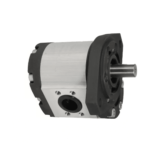
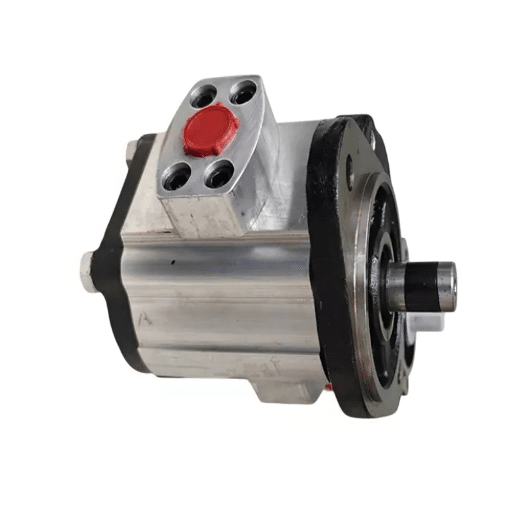
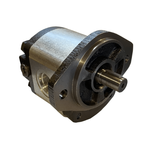
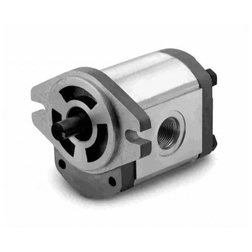
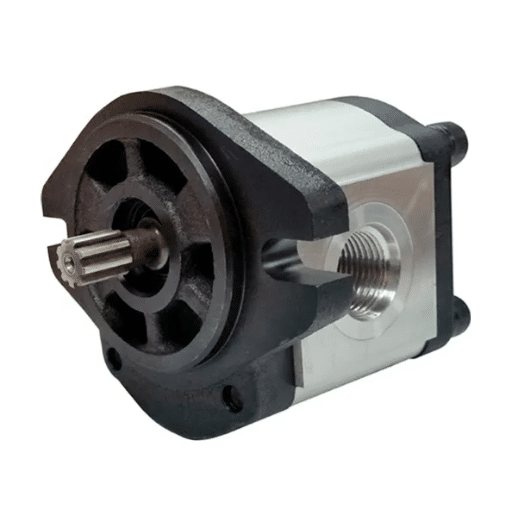
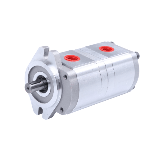
A tandem gear pump is a positive displacement hydraulic pump that houses two gear pump sections in one body, driven by a single common input shaft. Each section has its own gear pair and its own outlet port, so one drive produces two independent flows.
The industry uses three names for the same component: tandem, double, and dual gear pump. You’ll also see multi-section or two-section pump. They describe one pump with two outlet circuits, not two separate pumps bolted together.
Three design details shape how the unit behaves:
- One drive shaft. Both gear pairs turn at the same speed. Anything that changes shaft speed changes flow in both circuits at once.
- An intermediate partition plate. A separating plate sits between the sections. It prevents fluid from crossing from one circuit to the other. Some designs use one common inlet; others use dual inlets.
- Fixed displacement. Neither section adjusts its swept volume. Flow is proportional to shaft speed and section size, never to load.
Because the sections are independent, they can be sized differently. A common arrangement pairs a large section for a high-flow, low-pressure duty with a small section for a low-flow, high-pressure duty. That flexibility is the reason tandem pumps exist.
If you need a specification sheet for a two-circuit application before reading further, our applications engineers at LOYAL INDUSTRIAL PTE. LTD. can confirm section sizes and mounting interfaces against your duty.
Tandem vs Two-Stage vs Double-Acting Vane
Terminology in this corner of hydraulics is genuinely confusing, and ordering the wrong pump is an expensive way to learn the difference. The three terms describe three different machines.
| Term | What it is | Outlets | How it works | Key question |
|---|---|---|---|---|
| Tandem / double / dual gear pump | Two gear sections on one shaft | Two | Independent circuits, separate flows | What displacement does each circuit need? |
| Two-stage pump | One pump with internal staging | Usually one | Series flow with check and unloading logic, high flow then high pressure | Where does the transition pressure sit? |
| Double-acting vane pump | A vane pump family | One or two | Vane cartridges, often on a common shaft | Is a vane pump the right family at all? |
The distinction that causes the most trouble is tandem versus two-stage. A tandem pump delivers two independent flows. A two-stage pump delivers one flow, switching internally between a high-flow, low-pressure stage and a low-flow, high-pressure stage.
You may have heard that log splitter pumps are “two-stage.” Many aren’t. They are tandem pumps behaving like two-stage pumps, because the builder added a check valve and an unloading valve on the larger section. Our explanation of two-stage versus single-stage pumps walks through that circuit logic. The pump hardware is a separate question from the circuit it sits in.
Double-acting vane pumps get grouped in because they also put two pumping elements on one shaft, but they belong to a different family with different pressure limits, contamination tolerance, and cost. Our gear pump versus vane pump comparison covers that decision.
How a Tandem Gear Pump Works
The Per-Section Pumping Cycle
Each section of a tandem gear pump runs the standard external gear pump cycle. As the gears rotate, the meshing teeth separate on the inlet side and create expanding cavities, and that low-pressure zone draws fluid in. The fluid travels around the periphery trapped between the gear teeth and the housing wall. On the outlet side, the teeth mesh again and reduce the cavity volume, forcing fluid out under pressure.
Tight clearances limit how much back-leakage occurs, though some always does. That leakage is called slip. It rises with differential pressure and falls with viscosity, and on a truck-type unit running at 200 bar, roughly 10 to 15 percent of theoretical flow can be lost. Every added section adds another leak path, so a tandem pump shows slightly lower volumetric efficiency than an equivalent single section.
The Shared Shaft Is the Real Constraint
Here is the point that caught Daniel. Both sections start their suction and discharge cycles together because they share one shaft. They run in phase, at the same speed, for the life of the unit.
Each outlet sees only its own circuit pressure. Section one’s 90 bar doesn’t combine with section two’s 150 bar to produce 240 bar anywhere in the system. Pressure is set by the load on each circuit independently.
What does combine is the torque the two sections demand from the shared shaft, and therefore the power the prime mover must supply. When both circuits are loaded at once, the shaft carries the sum.
That is why a tandem pump often works in testing and fails in service. Single-function tests load one section at a time. The machine stalls only when the operator runs both functions together, which is exactly when the work happens.
A second consequence: the maximum speed of the unit is set by the section with the lowest rated speed. A large section and a small one rarely share the same limit.
Sizing a Tandem Gear Pump: Flow, Torque and Power

Work through these four steps in order. Each one feeds the next.
Step 1: Calculate Flow From Each Section Separately
Calculate each section on its own, using the same gear pump sizing method you would apply to a single-section unit. Never assume the two outlets deliver equal flow.
Q = Vg × n × ηv / 1,000
Where Q is flow in L/min, Vg is displacement in cm³/rev, n is shaft speed in RPM, and ηv is volumetric efficiency as a decimal.
Take the 32 + 16 cm³/rev unit at 1,450 RPM with an assumed volumetric efficiency of 0.90:
- Front section: 32 × 1,450 × 0.90 / 1,000 ≈ 41.8 L/min
- Rear section: 16 × 1,450 × 0.90 / 1,000 ≈ 20.9 L/min
- Combined: 62.7 L/min
Those per-section figures are what the two circuits receive. The combined figure matters for one thing only: the shared inlet, return line, filter, and cooler. Those components see everything at once. Work from the same geometry in reverse if you need to size a section against a target flow.
Step 2: Sum the Shaft Torque, Not the Pressure
This is the step that prevents Daniel’s failure. Compute the torque each section demands, then add them.
M = Vg × Δp / (20π × ηm)
Where M is torque in N·m, Vg is displacement in cm³/rev, Δp is the pressure differential in bar, and ηm is mechanical efficiency (about 0.90 for a well-built gear pump).
- Front section at 90 bar: 32 × 90 / (20π × 0.90) ≈ 50.9 N·m
- Rear section at 150 bar: 16 × 150 / (20π × 0.90) ≈ 42.4 N·m
- Sum at the drive shaft: 93.3 N·m
Now check that figure against the hardware. Shaft and coupling torque limits are real numbers, and manufacturers publish them. For a representative cast-iron tandem frame, published limits look like this:
| Element | Permissible torque |
|---|---|
| Splined shaft, SAE-A 5/8 in | 110 N·m (81 lb-ft) |
| Tapered shaft, 1:5, Ø17 mm | 150 N·m (110 lb-ft) |
| Coupling between section 1 and section 2 | 70 N·m (51 lb-ft) |
Note the coupling figure. The coupling between the two sections carries only the torque of the section behind it, not the sum. The stage-by-stage method that OEMs publish works from the last section back to the primary shaft, checking each joint in turn.
In our example, the inter-section coupling carries 42.4 N·m against a 70 N·m limit, which passes. The primary shaft carries 93.3 N·m against a 110 N·m limit, which also passes, but with less margin than most buyers expect from a “small” 48 cm³/rev combined unit.
Step 3: Size the Prime Mover for the Worst Simultaneous State
Convert torque demand into the power the motor or engine must supply.
P = Q × Δp / 600
Where P is hydraulic power in kW, Q is flow in L/min, and Δp is pressure in bar. Divide by overall efficiency (ηv × ηm) to get shaft power.
- Front section: 41.8 × 90 / 600 ≈ 6.3 kW
- Rear section: 20.9 × 150 / 600 ≈ 5.2 kW
- Total hydraulic power: 11.5 kW
- Shaft power at 0.81 overall efficiency: ≈ 14.2 kW
Two practical rules follow. First, size the prime mover against the simultaneous case, because that’s the state the machine stalls in. Second, use friction loss at operating temperature, not at cold start. Cold oil has high viscosity and high friction loss, and sizing on that figure produces an oversized, expensive motor.
Electric motors deserve particular care. A tandem pump on a motor that trips on thermal overload isn’t a pump defect. It’s a power calculation that ignored the combined load case.
Step 4: Size the Shared Inlet
If the two sections share a suction port, that single path must pass the summed instantaneous flow of both sections at once.
Port thread size isn’t a sizing rule. Check the whole suction path: hose bore, hose length, fittings, screen or strainer, tank outlet, and breather. Then verify with a vacuum reading at combined full flow.
Suction restriction is the most common cause of a tandem pump that performs well in warm weather and complains in winter. Cold oil is thick, the inlet can’t keep up, and the pump cavitates. The symptom sounds like a failing bearing. It’s usually a hose that’s one size too small.
Tandem Gear Pump Configurations and Circuits
Parallel Discharge for Independent Circuits
The default arrangement. Each section feeds its own circuit with its own relief valve, pressure path, and return. That’s what “two independent circuits from one drive” means in practice.
Never tee two positive displacement outlets together without designed logic. Two fixed-displacement pumps fighting over a common downstream pressure won’t share load predictably, and one section will tend to dominate.
Series or Cascade Sections
Some designs route one section’s discharge into the other’s inlet to build higher pressure. Cascaded arrangements must respect the downstream section’s pressure limit and usually need a case drain. Not every tandem housing is built for series operation, so confirm before specifying.
Combined Flow With Unloading Logic
This arrangement makes a tandem pump act like a two-stage pump. A check valve and an unloading valve let the large section contribute flow below a transition pressure, then unload it above that pressure, leaving the small section to carry the high-pressure work alone. It’s the correct way to get two-stage behavior from a tandem unit, and it’s the arrangement behind the log splitter misnomer discussed earlier. Our hydraulic power unit guide shows how this logic is packaged in a skid-mounted unit.
Three-Section and Multi-Section Pumps
Pumps with three or four sections are called multi-section, compound, or triple gear pumps, and machines with three or more independent circuits use them to avoid mounting multiple pumps. Torque stacking grows with every section added: a triple pump adds a third term to the shaft-torque sum, and the coupling limits between each pair of sections apply independently.
Where Tandem Gear Pumps Are Used

Mobile and Construction Machinery
Excavators, loaders, backhoes, and cranes are the classic application. One section drives a travel function while the other drives a work function, so the machine moves and operates without a second pump or a second drive point. Typical per-section displacement sits between 10 and 40 mL/r, with working pressures around 175 to 250 bar.
Truck Hydraulics
Tippers, tail lifts, and auxiliary cranes use tandem units where the large section lifts the body and the small section powers auxiliary equipment, all from one power take-off (PTO) point. Truck gear units tend to cap around 210 bar in practice, because slip becomes significant above that.
Agricultural, Industrial, and Marine Equipment
Tractors and harvesters pair steering and implement circuits, since steering needs dependable flow at all engine speeds while implements need volume. Presses and injection molding machines use tandem pumps for coarse feed, fine feed, and clamping duties, and compact skid-mounted power units use them to deliver multiple flows in a small envelope. Marine applications such as shipboard steering and deck machinery add corrosion-resistant housings and seal materials to the requirement.
Advantages and Limitations of Tandem Gear Pumps
Advantages
- Two circuits from one drive. One prime mover, one mounting point, two independent flows.
- Compact envelope. Suppliers report roughly 35 to 40 percent smaller footprint than two equivalent separate pumps. Treat that as a vendor-reported range and confirm dimensions for your frame.
- Simplified plumbing and drive. Fewer couplings, hoses, and fittings mean fewer leak points and less installation labor.
- Flexible section sizing. One high-flow section and one high-pressure section matched to two different duties.
- Predictable flow. Fixed displacement gives flow proportional to speed, which is easy to control and diagnose.
Limitations
- Slip. Roughly 10 to 15 percent at 200 bar, and each section adds a leak path.
- Maintenance complexity. Servicing a failed section usually means disassembling the entire unit.
- Shared suction constraint. A common inlet limits intake capacity and makes the pump sensitive to restriction and cavitation.
- Contamination sensitivity. Abrasive particles accelerate wear on gears, bearings, and seals.
- Higher upfront cost. The two-section design costs more than a single-section pump of the same total displacement.
When a Tandem Gear Pump Is Not the Right Answer
A tandem gear pump suits two circuits at moderate pressure from a single drive. It’s the wrong choice in three situations.
If the two circuits need very different filtration levels, separate pumps let you protect one and not the other. If the two functions never run simultaneously, one pump plus a flow divider or selector valve may cost less. If either circuit needs more than roughly 300 bar, an axial piston or radial piston pump is the correct family, and the gear pump’s contamination tolerance and cost advantage no longer outweigh its pressure limit.
Specification Checklist Before Ordering
Tandem pumps are configured to order, not pulled from a shelf. Send a supplier the following, and you’ll get an accurate quotation instead of an assumption.
| Information to confirm | Why it matters |
|---|---|
| Displacement of each section (cm³/rev) | Sets flow for each circuit and total shaft torque |
| Section order (which section is front) | Affects coupling torque and mechanical stress |
| Rotation direction | A reverse-rotation pump won’t work and may be damaged |
| Shaft type, size, and torque limit | Must exceed the summed torque of loaded sections |
| Inter-section coupling torque limit | Must exceed the torque of the rear section |
| Mounting flange and port sizes | Determines whether the pump fits the machine |
| Port orientation | Often decides whether hoses route cleanly |
| Continuous and peak pressure per section | Pressure ratings differ by section and frame |
| Simultaneous duty case | Sets the prime mover requirement |
| Inlet arrangement and suction components | Shared inlet must pass the summed flow |
| Return, filtration, and cooling capacity | Must handle combined flow |
| Oil grade, cleanliness code, operating temperature | Sets speed limits, efficiency, and life |
| Required documentation | Datasheet, curves, dimensions, seal and material spec |
For the interface details, our reference on SAE mounting and port standards covers the flange and port conventions you’ll need to match.
This is also the point to involve an engineer rather than a catalog. Tandem configuration is a specification exercise, not a lookup. Our applications team at LOYAL INDUSTRIAL PTE. LTD. reviews displacement ratio, section order, shaft limits, and rotation before a unit is built.
Maintenance and Fault Patterns
Preventive care follows standard gear pump practice, with one addition. Use the oil grade specified for the operating temperature range, keep the fluid at the ISO 4406 cleanliness class your manufacturer specifies, and inspect seals and bearings at scheduled intervals. The National Fluid Power Association publishes the fluid power standards behind those classifications if you need a reference for a procurement specification. Because the two sections wear asymmetrically, the one with the higher duty cycle or pressure shows wear first, and most designs don’t allow replacing a single section.
Three fault patterns are worth memorizing on a tandem gear pump:
- One section fails, the other still works. Normal and useful, but a partial failure can go unnoticed until the second circuit degrades. Track performance on both circuits, not just the one that stops the machine.
- Noise only on cold start. Suction starvation. Check the shared inlet path before suspecting the pump.
- Heat in one circuit only. Heat is a circuit diagnostic. A dumping relief valve or a restriction shows up as temperature long before it shows up as a failure.
For the single-section version of these symptoms, our gear pump troubleshooting guide covers diagnosis in more depth.
Sourcing: OEM Configuration and Factory-Direct Supply
Because a tandem pump is built to a configuration, sourcing one is closer to an OEM conversation than a catalog order.
When you evaluate a manufacturer, ask what happens before shipment. A meaningful sequence includes per-section flow and pressure testing, a leak test under pressure, and material and dimensional inspection. A generic “endurance tested” claim without parameters tells you nothing.
Interchange deserves caution. Replacement units cross-reference against families such as the Rexroth G2+G2 range, the CBTL and CBNL series, the PLP20 series, and OEM-fit truck pumps. Mounting and ports may match while displacement ratio, section order, or rotation differ. Verify all four, or you’ll fit a pump that runs backward or starves one circuit.
LOYAL INDUSTRIAL supplies tandem and multi-section gear pumps configured to specification, with multi-stage inspection and performance testing before shipment and export packaging built for international freight. Our overview of hydraulic gear pump manufacturers and OEM sourcing covers supplier vetting in more detail.
Request a tandem pump configuration and quotation with your per-section displacement, rotation, shaft type, and mounting requirements.
Frequently Asked Questions
Is a tandem gear pump the same as a two-stage pump?
No. A tandem gear pump has two independent sections feeding two separate circuits, usually with two outlets. A two-stage pump has internally staged sections that deliver a single flow, switching from high flow at low pressure to low flow at high pressure.
Do the pressures of the two sections add together?
No. Each circuit sees only its own load pressure. What adds is the torque and the power the two sections demand from the shared drive shaft when both are loaded at once. Sizing the prime mover against combined pressure produces an oversized motor and, more often, a tripping one.
Can the two sections have different displacements?
Yes, and they often should. Sections are commonly sized differently to match a high-flow, low-pressure duty and a low-flow, high-pressure duty. The displacement ratio is a selection decision, not a constraint.
What happens if one section of a tandem pump fails?
The other section usually continues to work, since the circuits are independent. The downside is that the failure can go unnoticed. On most designs, you can’t replace one section alone, so servicing means disassembling the whole unit.
What is the maximum pressure for a tandem gear pump?
Truck-type tandem gear units are typically limited to around 210 bar in practice, because slip becomes significant above that. High-pressure cast-iron designs reach 250 to 300 bar. Confirm the continuous and peak rating for the specific frame and displacement.
How do I size the shaft for a tandem pump?
Calculate the torque each section demands using M = Vg × Δp / (20π × ηm), then sum the sections that operate simultaneously. Check that sum against the primary shaft torque limit, and check the rear section’s torque alone against the inter-section coupling limit.
Conclusion
A tandem gear pump is one shaft, two gear sections, and two independent circuits. Get three things right, and the rest follows:
- Calculate flow for each section separately, then sum only for the shared inlet, return, and cooling path.
- Sum the torque, not the pressure. Check the sum against the primary shaft limit and the rear section’s torque alone against the coupling limit.
- Size the prime mover against the simultaneous load case, using friction loss at operating temperature.
Tandem pumps are specified, not selected. Every unit is built to a displacement ratio, a section order, a shaft type, and a rotation direction, which is why the checklist matters more than the catalog.
Renata, a production engineer at an equipment builder, consolidated two separate pumps into a single tandem unit on a compact loader. The machine lost four hose runs and their leak points, and gained a maintenance item her team now checks on both circuits because one section always wears first. The gain came from specifying the configuration correctly, not from the pump alone.
Before you order a tandem gear pump, write down the displacement each circuit needs, the pressure each will see, and whether they run together. If any of those are uncertain, contact LOYAL INDUSTRIAL PTE. LTD. for an engineering consultation, and we’ll confirm the section ratio, shaft limits, and mounting before the unit is built.