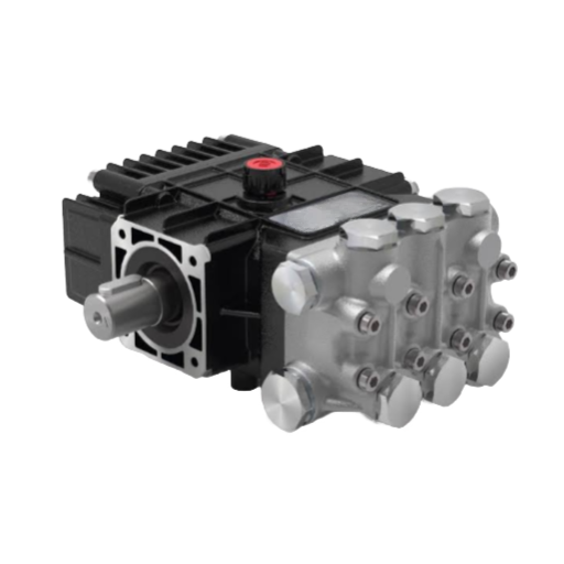
A buyer once specified a cleaning pump by pressure alone: “4,000 PSI, whatever flow.” The unit arrived, mounted, and ran. Then it tripped its motor on every bypass cycle and cavitated its inlet within a month. The pump was fine. The specification wasn’t.
Plunger pump sizing fails in predictable ways. A pump gets chosen on head pressure while the flow is ignored. The drive is undersized. The suction end is starved.
Every one of those is a sizing problem, not a component problem.
This guide turns a duty point (the flow and pressure your process actually needs) into a complete pump specification. You’ll determine plunger diameter, stroke, number of plungers, rotational speed, and drive horsepower.
We’ll work in both US and metric units, because the same method has to serve a North American cleaning rig and an export RO plant. If you want the wider picture first, the plunger pump complete guide covers pump types and architecture. This article is the sizing method itself.
What Plunger Pump Sizing Actually Means
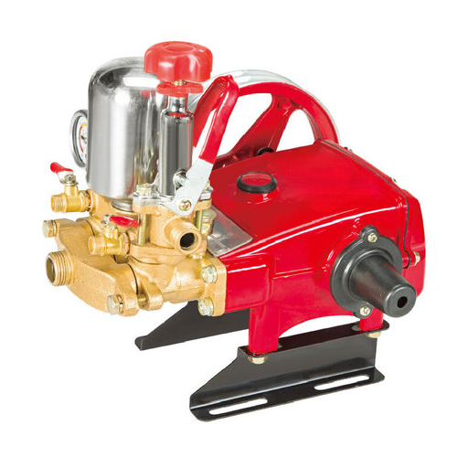
Plunger pump sizing is the process of matching a required flow rate and discharge pressure to a plunger diameter, stroke, cylinder count, and speed. You then confirm the drive power and the inlet conditions that keep the pump from cavitating.
Two facts drive the whole method. First, a plunger pump is a positive-displacement machine: it delivers flow, not pressure. The pump pushes a fixed volume of fluid per revolution.
The system (nozzle, valve, process resistance) creates whatever pressure that flow meets. Second, the pump is almost always single-acting: each plunger delivers one pulse per revolution.
So three numbers define your duty point: flow rate (GPM or L/min), discharge pressure (PSI or bar), and speed (rpm). Everything else (plunger size, cylinder count, motor) follows.
For the full comparison, including efficiency and service-life figures, see plunger pump vs piston pump.
Step 1: Determine the Flow Your Duty Requires
Flow is the first specification to lock down. It sets pump size, motor rating, and cost. Pressure tunes the work; flow determines how much work you can do in an hour. In cleaning and process work, that’s the difference between finishing a job in four hours and finishing it in eight.
Determine flow from the application, not the pump catalog:
- Cleaning and blasting: the total flow of your nozzle set at the target pressure.
- Process and chemical injection: the dosing rate at the required pressure.
- Reverse osmosis and desalination: the feed flow demanded by the membrane array and recovery ratio.
- Waterjet: the intensifier’s rated output at cutting pressure.
Then add headroom. Size for 10–20% above your minimum required flow to absorb wear, pressure spikes, and duty peaks. A cleaning duty needing 4.0 GPM gets specified at roughly 4.6 GPM. A process needing 18 L/min gets specified at 21 L/min.
Skip this margin and the pump “suddenly” falls short after a few thousand hours.
Step 2: Calculate the Pump’s Ideal Flow from Plunger Geometry
This is the step most sizing guides skip, and it’s where the pump gets its actual size. Because a plunger pump is positive displacement, ideal flow depends only on geometry and speed. Pressure doesn’t enter the equation.
For each plunger, the volume displaced per revolution is the plunger face area multiplied by the stroke. Multiply by the number of plungers and the rotational speed, and you have the ideal (theoretical) flow.
Metric units
Q (L/min) = A × s × n × m ÷ 1,000,000
A = π × d² ÷ 4   (plunger face area, mm²)
s = stroke (mm)   n = pump speed (rpm)   m = number of plungers
US units (per-cylinder, then × m)
GPM = 0.0034 × d² × L × N × m
d = plunger diameter (in)   L = stroke (in)   N = strokes/min   m = number of plungers
The table method: GPM = GPR × RPM
Manufacturers publish a simpler route. A pump data sheet lists displacement per revolution, gallons per revolution (GPR), for each plunger size. You then pick a speed directly:
GPM = GPR × RPM and RPM = desired GPM ÷ GPRA published triplex table, for instance, gives a 2.000-in plunger 0.0816 gal/rev. At 200 rpm that’s 16.3 GPM; at 625 rpm it’s 51.0 GPM. This is the fastest way to size once you’re inside a specific product line, and it removes any unit-conversion risk.
Check the plunger speed
Flow is only half the geometry decision. Plunger speed governs wear, seal life, and cavitation risk, and it’s the constraint most buyers never consider. Compute the mean plunger speed:
Sp (m/s) = s × n ÷ 30,000Keep it under about 1.0–1.2 m/s (roughly 3–4 ft/s). Above that, packing and plungers wear quickly and suction performance drops.
If your calculation exceeds the limit, reduce the speed, shorten the stroke, or reduce plunger diameter. Then increase speed elsewhere to recover flow. This is why larger plunger pumps run at only 300–500 rpm in continuous duty.
Worked geometry example
A triplex pump (m = 3) with 40-mm plungers, an 80-mm stroke, and a target speed of 300 rpm:
A = π × 40² ÷ 4 = 1,257 mm²
Q = 1,257 × 80 × 300 × 3 ÷ 1,000,000 = 90.5 L/min ideal
Sp = 80 × 300 ÷ 30,000 = 0.80 m/s ✓ within limit
Ideal output is about 90.5 L/min (24 GPM) before efficiency losses. To understand the single-plunger cycle behind this math, see how a plunger pump works.
Step 3: Account for Volumetric Efficiency and Slip
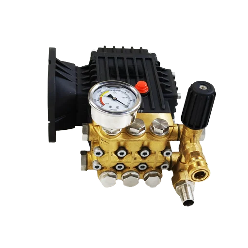
Ideal flow isn’t delivered flow. Some fluid slips back past the plunger packing and the valves every stroke, so actual output is always lower than theoretical. That loss is the slip. Its inverse is volumetric efficiency:
Q_actual = Q_ideal × η_vol η_vol = Q_actual ÷ Q_ideal × 100Well-maintained plunger pumps hold roughly 85–95% volumetric efficiency on clean, low-viscosity fluid. Slip is typically 2–6% at moderate speed. It rises with discharge pressure and with fluid temperature, and it falls as viscosity rises.
So you size the ideal displacement above the flow you need:
Q_ideal = Q_required ÷ η_volIf you need 90 L/min delivered at 92% efficiency, specify roughly 98 L/min of ideal displacement. Confirm the exact figure against the supplier’s performance table. Efficiency values vary by pump design, fluid, and pressure, and the catalog number is the final authority.
Step 4: Establish Operating Pressure and Pick the Plunger Size Class
Pressure is imposed by the system, not chosen for the pump. The nozzle, the valve setting, the process resistance, and the discharge line all define the pressure your flow must overcome. Your job is to confirm the plunger size from Step 2 can safely handle it.
Here’s the trade-off that governs every selection: at a given drive power, a larger plunger delivers more flow at lower maximum pressure. A smaller plunger delivers less flow at higher pressure. Plunger face area and pressure act together on the connecting rod, so maximum allowable pressure falls as plunger diameter rises.
| Application | Typical operating pressure |
|---|---|
| Car washing / light cleaning | 1,000–3,000 PSI |
| Commercial pressure washing | 3,000–5,000 PSI |
| Industrial surface preparation | 5,000–20,000 PSI |
| Hydro-demolition | 10,000–40,000 PSI |
| Waterjet cutting | 40,000–100,000 PSI |
| Oil-well stimulation | 5,000–20,000 PSI |
A practical rule from field practice: sustained pressures above roughly 5,000–7,500 PSI with clean fluid favor a plunger pump. Abrasive fluids favor a piston pump with replaceable liners.
One more check is worth doing: the rod load, L = plunger area × pressure. It confirms the power end can carry the thrust your pressure and plunger size create.
Step 5: Size the Drive, Brake Horsepower and Motor
Once flow and pressure are fixed, the drive power follows. Two systems with the same flow can differ widely in power demand, so this step isn’t optional and can’t be approximated.
US units
Water HP = (GPM × PSI) ÷ 1,714
Brake HP = Water HP ÷ η_overall
The constant 1,714 is the ideal water-horsepower figure. Published brake-horsepower shortcuts use a larger divisor because they already fold in efficiency.
You’ll see roughly ÷ 1,460 at 85% overall efficiency (CAT Pumps) or ÷ 1,543 (reciprocating-pump catalogs). These aren’t contradictory; they sit at different points on the same curve. Pick one, state its efficiency assumption, and stay consistent.
Metric units
kW = (L/min × bar) ÷ (600 × η) η = 85–92%Add a service factor
Size the motor above the brake-horsepower figure. A service factor of 1.15–1.20 keeps the motor off its thermal limit during bypass, hot days, and wear.
An undersized motor doesn’t simply run slow. It runs at full nameplate continuously and trips on overload the moment the unloader bypasses. An oversized motor wastes energy. There’s no safe fudge either way, so you size the motor to the equation.
Worked power examples
US: 4.6 GPM at 3,000 PSI.
Water HP = 4.6 × 3,000 ÷ 1,714 = 8.05 HP
Brake HP = 8.05 ÷ 0.90 = 8.95 HP
Motor = 8.95 × 1.20 ≈ 10.7 HP → specify ~11 HP
Metric: 20 L/min at 200 bar.
kW = (20 × 200) ÷ (600 × 0.90) = 7.4 kW
Motor = 7.4 × 1.15 ≈ 8.5 kW → specify the next standard motor
For interactive help with these figures, use the hydraulic pump horsepower calculator.
The NPSH and Flooded-Inlet Check
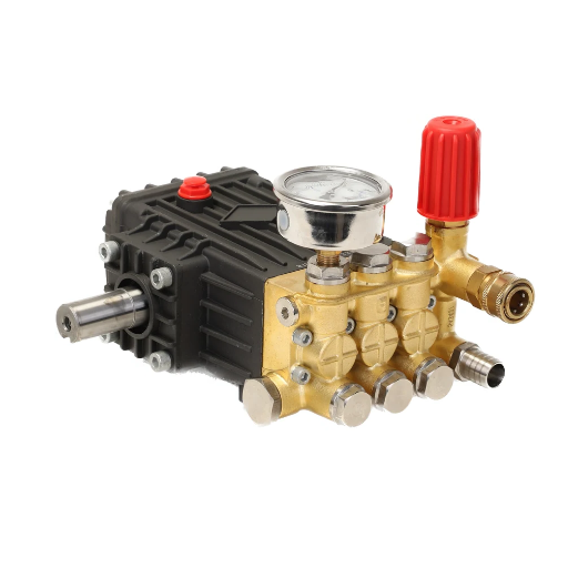
This is the step unique to plunger pumps, and the one the largest buyer’s guides leave out. Unlike a centrifugal pump, a plunger pump does not lift fluid. It has to be fed. Most designs need a flooded inlet, a gravity head, or a booster supplying positive inlet pressure, typically 60–70 psi on industrial pumps.
The pump also needs enough net positive suction head to fill each cylinder against the suction valve, the pipe friction, and the pulsating flow:
NPSHa > NPSHr + margin (margin typically > 1 m)Two details matter more than the headline comparison. First, because plunger pumps pulse, the fluid in the suction line accelerates and decelerates each stroke. That acceleration head (p_ac) must be subtracted from your available NPSH. A static pressure reading on the suction side isn’t enough:
NPSHa = p_g + p_z − p_vp − p_f − p_acSecond, inlet supply is a hard limit, not a suggestion. Practitioners phrase it plainly: the pump can’t make flow it isn’t given. As a rule, supply at least 20% more flow than the pump draws. Use a 50-mesh or finer inlet filter, and keep suction lines short, direct, and at least one size larger than the pump inlet.
Get this wrong, and the pump tells you: harsh noise, surging pressure, hot seals, and, within weeks, pitted plungers and a scored manifold. A service rig whose pump had been rebuilt twice finally traced the damage to an undersized inlet hose and a half-clogged filter. The pump was never the problem.
The suction side was.
Full Plunger Pump Sizing Examples
Example 1, Triplex cleaning pump (US units)
Duty: 5.0 GPM at 3,500 PSI, intermittent duty.
- Flow: add 10% headroom → 5.5 GPM.
- Ideal flow: ÷ 0.92 volumetric efficiency → ~6.0 GPM of displacement.
- Geometry: from a displacement table, 18-mm (0.71-in) plungers on a 21-mm (0.83-in) stroke at ~1,400 rpm, triplex, deliver about 6.0 GPM. Plunger speed = 21 × 1,400 ÷ 30,000 ≈ 0.98 m/s, right at the practical ceiling. That’s normal for a compact, high-speed cleaning pump. For continuous duty, select a slower, larger unit.
- Pressure check: 3,500 PSI (241 bar) is within this plunger class.
- Drive: Water HP = 5.0 × 3,500 ÷ 1,714 = 10.2 HP; brake HP = 10.2 ÷ 0.90 = 11.3 HP; with a 1.15 service factor → ~13 HP drive.
- Inlet: confirm a flooded or boosted inlet delivering ≥ 20% more than 5 GPM.
Example 2, Quintuplex RO feed pump (metric units, continuous)
Duty: 30 m³/h (500 L/min) at 70 bar, 24/7.
- Flow: add 10% headroom → 550 L/min.
- Ideal flow: ÷ 0.92 → ~600 L/min of displacement.
- Geometry: a quintuplex (m = 5) with 80-mm plungers on a 70-mm stroke at ~340 rpm gives ~600 L/min. Plunger speed = 70 × 340 ÷ 30,000 ≈ 0.80 m/s, comfortably within limits, and the low speed suits continuous service.
- Drive: kW = (500 × 70) ÷ (600 × 0.90) = 64.8 kW; with a 1.15 service factor → ~75 kW motor. Derate by around 10% more for 24/7 duty and elevated fluid temperature.
- Materials: RO feed water calls for 316L or duplex wetted parts.
- Inlet: a feed tank providing flooded suction; verify NPSHa exceeds NPSHr by more than 1 m, including acceleration head.
Choosing five plungers over three is a separate decision driven by flow smoothness and vibration. See triplex vs quintuplex plunger pump.
Selection summary
| Input / Output | Example 1 (triplex) | Example 2 (quintuplex) |
|---|---|---|
| Required flow | 5.0 GPM | 500 L/min (30 m³/h) |
| Discharge pressure | 3,500 PSI | 70 bar |
| Plungers | 3 | 5 |
| Plunger / stroke | 18 / 21 mm | 80 / 70 mm |
| Speed | ~1,400 rpm | ~340 rpm |
| Plunger speed | ~0.98 m/s | ~0.80 m/s |
| Drive (with service factor) | ~13 HP | ~75 kW |
| Duty | Intermittent | Continuous 24/7 |
Plunger Pump Sizing Checklist and Common Mistakes
Run this checklist before you send a single RFQ:
- Required flow defined from the application, plus 10–20% headroom
- Discharge pressure established from the system, not the catalog
- Ideal flow calculated from plunger geometry (or a GPR table)
- Volumetric efficiency / slip applied (Q_ideal = Q_required ÷ η_vol)
- Plunger speed checked and kept under ~1.0–1.2 m/s
- Plunger size vs maximum pressure trade-off confirmed
- Drive power calculated and a service factor of 1.15–1.20 added
- NPSHa verified against NPSHr, including acceleration head
- Flooded inlet or booster confirmed
- Duty cycle set (intermittent vs continuous, with derating)
- Wetted materials matched to the fluid
Avoid these six mistakes: shopping by PSI alone; ignoring slip; ignoring the rpm / plunger-speed ceiling; skipping the NPSH check; assuming the pump will self-prime; and undersizing the motor. Each one shows up later as a shortened pump life or a stalled drive.
When you’re ready to source, LOYAL INDUSTRIAL PTE. LTD. supplies multiple pump families and configurations.
Frequently Asked Questions
How do you size a plunger pump?
Fix the duty point first: required flow (add 10–20%) and discharge pressure. Calculate ideal flow from plunger diameter, stroke, cylinder count, and speed. Correct for volumetric efficiency, confirm the plunger class handles the pressure, size the drive power with a service factor, and verify the inlet provides enough NPSH.
What is the flow-rate formula for a plunger pump?
In metric units, Q (L/min) = A × s × n × m ÷ 1,000,000, where A is plunger area in mm², s is stroke in mm, n is speed in rpm, and m is the number of plungers. In US units, GPM = 0.0034 × d² × L × N × m. Manufacturers also publish gal-per-revolution (GPR) tables, where GPM = GPR × RPM.
How do I calculate plunger pump horsepower?
US: brake HP = (GPM × PSI) ÷ 1,714 ÷ efficiency. Metric: kW = (L/min × bar) ÷ (600 × efficiency). Efficiency typically runs 85–92%. Add a 1.15–1.20 service factor before selecting the motor.
Do plunger pumps need a flooded inlet?
Yes. Plunger pumps don’t self-prime. Most require a flooded inlet or a booster supplying positive inlet pressure (commonly 60–70 psi on industrial units). A starved inlet causes cavitation, which pits plungers and damages the manifold.
Why does a bigger plunger give higher flow but lower pressure?
Plunger area and pressure act together on the connecting rod. At a given drive power, a larger plunger moves more volume per stroke but reaches a lower maximum pressure before the rod is overloaded. Smaller plungers trade flow for higher pressure.
How fast should a plunger pump run?
Enough speed to make your required flow while keeping plunger speed under about 1.0–1.2 m/s. Larger pumps in continuous duty commonly run at 300–500 rpm. Compact high-speed units can run near 1,400 rpm for intermittent work.
Conclusion
Plunger pump sizing is a sequence, not a guess. Define the duty point, calculate ideal flow from plunger geometry, correct for slip, confirm the plunger class suits the pressure, size the drive with a service factor, and verify the inlet. Flow comes first, because it drives production: the pump delivers flow, and the system makes pressure.
Get those five steps right, and the pump performs as specified for years. Get the inlet or the motor wrong and no amount of quality in the pump itself will save the installation. Treat the NPSH and flooded-inlet check as a sizing step in its own right, not an afterthought.
If you’d rather not size it alone, our engineers will take your duty point and return a complete specification: plunger size, speed, drive, and materials. Request a technical specification sheet or an OEM plunger pump quotation from LOYAL INDUSTRIAL PTE. LTD., and we’ll match the pump to your application, not the other way around.