In a study of various engineering sources, the gear pump displacement formula was wrong by a sufficient percent, something close to twenty percent. This error does not spring from computational approximation and digit flipping. The error stems rather from a condition that can lead to a replacement pump not delivering the required flow, causing longer cycle times, or causing the motor to operate at a speed higher than the specified one.
Almost all hydraulic systems design engineers and procurement officers have at some point in time had to rely on a fast online reference. Whether it is sizing a new system or determining the volume of a pump that is supposed to replace an already worn-out one, the needed displacement value should be found within a short period. A good hydraulic pump displacement formula gives information about the appropriate component at the first attempt.
In this guide, you will be given the full data and formulas for displacement on gear, piston, and vane hydraulic pumps. You will be given corresponding tasks in both imperial and metric units, understand how this differs from the standard flow and obtain some hints pertaining to how to use the displacement data when one needs the manufacturer to quote.
Need help verifying displacement requirements for your system? Request a technical consultation and our engineering team will confirm your pump specifications, check the hydraulic pump horsepower calculator results, and validate motor compatibility.
What Is Pump Displacement?
Definition and Engineering Context
The pump displacement is a term used within the field of pumps and it refers to the theoretical volume of fluid that a pump can move in one revolution of the driven shaft. Normally, this figure is given in cubic inches per revolution (in3/rev) or cubic centimeters per revolution (cc/rev) and for each one full turn of the input shaft. In the typical situation, when the displacement is specified as 1.5 in3/rev, it would mean that a mass of 1.5 cubic inches of fluid would be pumped during each complete rotation.
Displacement refers to the volume capacity. Pressure should not be thought of in the same sense as flow in pumps. This is because pressure is caused by the inhibition of the free flow of the liquid inside the piping system. A common misconception is that a bigger size/displacement pump will provide a higher level of pressure. However, the correct operation of a pump imparts hydraulic energy, which in turn increases the rate of flow at a given speed. The pressure is determined by the load.
Fixed Displacement vs. Variable Displacement
The fixed displacement pump is mostly used in hydraulic systems where a pump without variable displacement is capable of handling an extra load. It means the pump that has a fixed displacement volume is in the operation of the flow operation, which is based on the period as well as the speed variation capability of the shaft; in other words, flow is varied only when the rotation speed is changed. Gear and most of the vane-type pumps operate at fixed displacement volume.
A variable displacement pump is a type of hydraulic pump whose internal configuration can be changed in such a way as to alter the volume per revolution without necessarily changing the motor speed that it is running. Axial piston pumps with swashplate mechanisms are the most common example. This feature allows the system to adjust the input power without having to change the motoring speed of the prime mover, and indicates optimal utilization of the input sources.
Why Displacement Matters for System Design
Selecting the wrong displacement creates one of two problems. If the pump’s bore and stroke are significantly larger than required, the pump will spend vital energy to heat the excess, also killing the capacity to be squeezed into a smaller motor. On the contrary, if the demand is not satisfied, some non-effective time is necessary in each cycle, which makes the undersized pump fail. From an economic point of view, both erroneous results require more money to be spent operationally and reduce machine life significantly.
Estimating the correct hydraulic pump displacement allows engineers to mate the pump to the motor, select an appropriate reservoir size, and even predict the heat produced by the system before building anything.
Want to learn more about the 20 GPM Hydraulic Pump? Please check out our guide about the 20 GPM Hydraulic Pump.
The Core Hydraulic Pump Displacement Formula

Calculate Displacement from Flow and Speed (Imperial)
The most common hydraulic pump displacement formula is a formula of the targeted hydraulic flow and the actual operating speed, determining the targeted displacement. Such is the formula adopted by system designers when the GPM and the motor RPM are known.
Displacement (in3/rev) = (231 x GPM) / RPM
An additional constant, 231, shows how many cubic centimeters are in 1 gallon. GPM is used to denote the flow rate to be provided in gallons per minute. RPM refers to the speed of the rotating unit in this case the pump shaft, in revolutions per minute.
For example, if a system requires 12 GPM at 1,800 RPM:
Displacement = (231 x 12) / 1,800 = 2,772 / 1,800 = 1.54 in3/rev
This calculation gives the theoretical displacement needed to achieve the target flow under ideal conditions.
Metric Formula: cc/rev from L/min and RPM
For metric system design, the formula uses liters per minute and cubic centimeters per revolution.
Displacement (cc/rev) = (1,000 x L/min) / RPM
The constant 1,000 converts liters to cubic centimeters. One liter equals 1,000 cubic centimeters.
For example, if a system requires 45 L/min at 1,800 RPM:
Displacement = (1,000 x 45) / 1,800 = 45,000 / 1,800 = 25 cc/rev
Calculate Flow from Known Displacement
When you already know a pump’s displacement and operating speed, you can calculate theoretical flow output.
GPM = (RPM x Displacement in3/rev) / 231
For example, a pump with 2.0 in3/rev displacement running at 1,800 RPM produces:
GPM = (1,800 x 2.0) / 231 = 3,600 / 231 = 15.58 GPM
Quick Reference Table: GPM and RPM to Displacement
| Required GPM | 1,200 RPM | 1,800 RPM | 2,400 RPM |
|---|---|---|---|
| 5 GPM | 0.96 in3/rev | 0.64 in3/rev | 0.48 in3/rev |
| 10 GPM | 1.93 in3/rev | 1.28 in3/rev | 0.96 in3/rev |
| 15 GPM | 2.89 in3/rev | 1.93 in3/rev | 1.44 in3/rev |
| 20 GPM | 3.85 in3/rev | 2.57 in3/rev | 1.93 in3/rev |
| 25 GPM | 4.81 in3/rev | 3.21 in3/rev | 2.41 in3/rev |
| 30 GPM | 5.78 in3/rev | 3.85 in3/rev | 2.89 in3/rev |
Need a pump with a specific displacement for your system? Request a technical specification and our engineering team will match displacement, flow, and pressure requirements to the correct pump model.
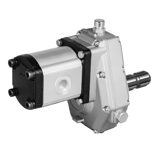
Gear Pump Displacement Formula
Theoretical Displacement from Gear Dimensions
If the undecipherable or non-existent nameplate makes it impossible to do so, estimations can be performed using inner dimensions, leading to gear pump displacement. The formula of the maximum geometrically accurate shape of the gear chamber is a hollow cylinder.
V = ((D2 – d2) / 4) x gW x pi
Where:
- V = Displacement in in3/rev
- D = Gear tip diameter (outside diameter) in inches
- d = Gear root diameter in inches
- gW = Gear width (face width) in inches
- pi = 3.1416
The formula calculates the volume of the gap inside the tip radius and root radius of the gear multiplied by the gear width of one gear. Henceforth, the result is multiplied by pi to reflect for the circular locations of the tooth chambers.
Correct Formula vs. Common Incorrect Variants
Several alternative formulas appear in online resources and old engineering handbooks. One popular variant uses center distance (c) instead of root diameter:
Incorrect variant: V = c x (D – c) x gW x pi
The formula is unacceptable because it lacks the actual calculation of fluid chamber volume and can be off to as much as 20%. If the static case is to be listed, one primary disadvantage of this model is the method by which the value of the tooth tip length can be specified, and the limitations to the shapes of gear teeth. The authors also present a detailed bibliography.
Another acceptable alternative uses body bore width (W) instead of root diameter:
V = (2D – W) x (W – D) x gW x pi
This version works if you do not need to get the radius of the geometry, and you bore down on either of the circles only. There is a drawback in applying this equation because the dimensions have to be right for it to work.
Worked Example: Calculating Gear Pump Displacement
A maintenance technician measures the internal gears of an unmarked pump and records the following dimensions:
- Gear tip diameter (D) = 2.00 inches
- Gear root diameter (d) = 1.60 inches
- Gear width (gW) = 1.50 inches
Applying the primary gear pump displacement formula:
V = ((2.002 – 1.602) / 4) x 1.50 x 3.1416
V = ((4.00 – 2.56) / 4) x 1.50 x 3.1416
V = (1.44 / 4) x 1.50 x 3.1416
V = 0.36 x 1.50 x 3.1416
V = 1.70 in3/rev
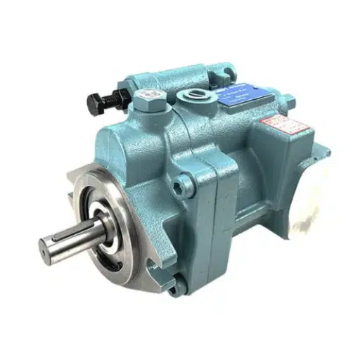
Piston Pump Displacement Formula

Axial Piston Pump Displacement
In the case of variable-displacement axial piston pumps, the plate angular position is the most notable parameter. The pump operates at full displacement when the angular position of the plate is at its maximum. The plate is set at zero degrees; resulting in nearly zero displacement. As a result, the flow rate demanded by the hydraulic cylinder is not controlled by the pump neither by varying the spindle speed.
V = (pi x d2 x D x tan(gamma) x z) / 4
Where:
- V = Displacement in in3/rev or cc/rev (consistent units)
- d = Piston diameter
- D = Pitch circle diameter of the piston arrangement
- gamma = Swashplate inclination angle
- z = Number of pistons
- pi = 3.1416
In the case of variable-displacement axial piston pumps, the plate angular position is the most notable parameter. The pump operates at full displacement when the angular position of the plate is at its maximum. The plate is set at zero degrees, resulting in nearly zero displacement. As a result, the flow rate demanded by the hydraulic cylinder is not controlled by the pump nor by varying the spindle speed.
Radial Piston Pump Displacement
This type of machine, that is, radial piston pumps, incorporates the pistons that are mounted, centered on the rotation axis, and operated by a cam mechanism. The same applies to calculations of the displacement field; however, the geometry parameter will not be the swashplate angle but the eccentricity and cam profile.
Most of the time, in formal documents and design works for a system procurement application, rated displacement data is available from the manufacturer’s catalogue. When working on custom designs or duplicating a product, a quite close version of the axial piston arrangement will often be required.
Worked Example: Axial Piston Pump Calculation
An engineer is evaluating an axial piston pump with the following specifications:
- Piston diameter (d) = 0.50 inches
- Pitch circle diameter (D) = 2.50 inches
- Swashplate angle (gamma) = 18 degrees
- Number of pistons (z) = 9
First, calculate tan(18 degrees) = 0.3249
V = (3.1416 x 0.502 x 2.50 x 0.3249 x 9) / 4
V = (3.1416 x 0.25 x 2.50 x 0.3249 x 9) / 4
V = (5.73) / 4
V = 1.43 in3/rev
At 1,800 RPM, this pump theoretically produces:
GPM = (1,800 x 1.43) / 231 = 11.14 GPM
Vane Pump Displacement Formula
Theoretical Displacement Calculation
A vane pump entails some sliding vanes with a central rotation mechanism that is driven by an axle, which also makes some spins. The distance between the central rotation of the central rotor and the outer ring, called the eccentricity, results in the creation of recurring expansion and contraction of a chamber with fluid in it.
The approximate displacement formula is:
V = 2 x B x e x (D – e) x pi
Where:
- V = Displacement in in3/rev
- B = Vane width (rotor thickness) in inches
- e = Eccentricity (offset between rotor center and cam ring center) in inches
- D = Cam ring inner diameter in inches
- pi = 3.1416
This equation then finds the volumes between the rotation vanes and the cam ring to estimate the motion of fluid in the system. It is notable that the amount of any fluid that occupies in a pump is always tabulated in most large or small pumps due to structural design since the pump rotor is too large or too small for the space available.
Worked Example: Vane Pump Displacement
A vane pump has the following internal dimensions:
- Vane width (B) = 1.25 inches
- Eccentricity (e) = 0.15 inches
- Cam ring diameter (D) = 2.75 inches
V = 2 x 1.25 x 0.15 x (2.75 – 0.15) x 3.1416
V = 2 x 1.25 x 0.15 x 2.60 x 3.1416
V = 3.06 in3/rev
At 1,800 RPM, this pump theoretically produces:
GPM = (1,800 x 3.06) / 231 = 23.84 GPM
Theoretical vs. Actual Displacement

Volumetric Efficiency by Pump Type
In that case, the theoretical volume has been assumed to have no leakage and is achievable with a perfect seal. While orienting oversized pumps always follows the calculation of the theoretical value, oversized pumps will be selected in the same conditions, and sometimes even smaller ones will be taken into use since the void created during pump operation may cause leakage of the pumped medium.
Volumetric efficiency measures this difference:
Volumetric Efficiency = (Actual Flow / Theoretical Flow) x 100%
Typical values at rated conditions:
| Pump Type | Volumetric Efficiency |
|---|---|
| Gear pump | 85% – 92% |
| Piston pump | 90% – 95% |
| Vane pump | 85% – 90% |
New pumps operate at the higher end of these ranges. Worn pumps with enlarged clearances may drop below 80%.
Why Actual Flow Is Always Less Than Theoretical
Movement (slip) inside a pump operates in various ways. Leaks in gear pumps will come mostly from between teeth and the tooth tips and end plates. In a piston pump, it will access the seemingly closed systems with piston rings and the valve plate, while in vane pumps, it sneaks through the vane seals and in the cam ring.
Fluid’s thickness has an effect on its actual flow capabilities as well. It’s more difficult for the thinner fluids to hold than the thick ones. And lessen the viscosity (thick-like quality) with a greater rate while increasing the slippage. It is, however, true that at the start with the thick fluid, slippage temporarily increases the fill of volumetric efficiency, but does not increase the mechanical drag in such a scenario.
Adjusting Displacement Selection for Real-World Performance
One of the most important things that engineers should consider when selecting a pump for a system is the proper theoretical surge volume. Such practice helps to avoid efficiency markings and volumetric efficiency losses.
Required Theoretical Displacement = (231 x Required GPM) / (RPM x Volumetric Efficiency)
For example, if a system needs 10 GPM at 1,800 RPM using a gear pump with 88% volumetric efficiency:
Required Displacement = (231 x 10) / (1,800 x 0.88) = 2,310 / 1,584 = 1.46 in3/rev
Without considering efficiency, the calculated actual GI (Gearbox Index) would be 1.28 cubic inches per revolution. Based on this actual GI, the pump would achieve only 8.8 GPM which is too short due to system requirements.
Hydraulic Pump Displacement Reference Table
Common GPM and RPM Combinations with Efficiency Adjustment
The following table shows the theoretical displacement required for common flow and speed combinations, adjusted for 88% volumetric efficiency:
| Required GPM | 1,200 RPM | 1,800 RPM | 2,400 RPM |
|---|---|---|---|
| 5 GPM | 1.09 in3/rev | 0.73 in3/rev | 0.55 in3/rev |
| 10 GPM | 2.19 in3/rev | 1.46 in3/rev | 1.09 in3/rev |
| 15 GPM | 3.28 in3/rev | 2.19 in3/rev | 1.64 in3/rev |
| 20 GPM | 4.38 in3/rev | 2.92 in3/rev | 2.19 in3/rev |
| 25 GPM | 5.47 in3/rev | 3.65 in3/rev | 2.74 in3/rev |
| 30 GPM | 6.56 in3/rev | 4.38 in3/rev | 3.28 in3/rev |
Displacement to Flow Quick Lookup (1,800 RPM)
| Displacement | Theoretical GPM | Actual GPM (88% Eff.) |
|---|---|---|
| 0.50 in3/rev | 3.90 GPM | 3.43 GPM |
| 1.00 in3/rev | 7.79 GPM | 6.86 GPM |
| 1.50 in3/rev | 11.69 GPM | 10.29 GPM |
| 2.00 in3/rev | 15.58 GPM | 13.71 GPM |
| 2.50 in3/rev | 19.48 GPM | 17.14 GPM |
| 3.00 in3/rev | 23.38 GPM | 20.57 GPM |
Using Displacement Data for Pump Procurement
Specifying Displacement in RFQs
When asking for a quotation to a pump manufacturer, do not forget to indicate the calculated displacement according to ISO standards in the technical specification. It should also be mentioned whether it is the theoretical volume or one that includes volumetric efficiency.
A complete specification should include:
- Required displacement at rated speed
- Operating RPM range
- Acceptable volumetric efficiency minimum
- Fluid type and viscosity range
- Mounting configuration and shaft requirements
Verifying Manufacturer Catalog Data
Manufacturer datasheets usually provide somewhat optimistic displacement value that corresponds to a specific set of design and operating conditions. Before using it, better check if your speed and fluid are respectively similar to these conditions! A pump with a 2,000 RPM governed test may give less volume displacement than it would for a set to a 1500 RPM system.
Ask your vendors to provide performance test results at the same conditions as your system operates. Good manufacturers will include efficiency curves with the catalogue, which indicate the varying values of volumetric efficiency at various speeds and pressures.
Fixed vs. Variable Displacement: Which to Source?
Fixed displacement pumps are cheap and easier to manufacture than others. They should be used where there is no load variation and speed is constant. Some implements that require a very specific speed and output include a log splitter, a simple press or a conveyor drive.
Positive displacement pump units not only come with a higher price but they also cut energy costs in facilities having either high or low power demand. They should be designed to be able to withstand the most attention to in the event there are frequent and severe load changes or flow adjustment needs that are more stringent. Among others, these include hydraulic equipment in excavators, in the plunger hydraulic channels of an injection molding tool, and an industrial press apparatus with adjustable speed.
Looking for a pump with exact displacement for your machinery? Request a custom hydraulic pump specification and our engineering team will match displacement, flow, and pressure requirements to your exact application.
Common Mistakes When Calculating Pump Displacement

Using Theoretical Displacement Without Efficiency Correction
The volumetric efficiency factor is also often disregarded when making the sizing of the pump. A pump that is chosen just because theoretical displacement calculations have shown that it’s the value that is needed is misleading. Therefore, the efficiency of the pump under its sizing and operating requirements should always be considered.
Mixing Imperial and Metric Units
Inconsistencies in units in the same calculation pose a problem when calculating displacement. For example, never use cc/rev in the formula, considering that there are 231 as the gallon conversion units. Ensure uniformity in units throughout the calculation and only resort to conversions at the last step.
Confusing Displacement with Pressure Rating
Displacement sets the pace of the flow for each revolution. An aspect termed pressure rating specifies the standard limit up to which the pump is put under operational pressure. It is to be noted that a pump with a large displacement factor does not operate with such high pressures. The pressure levels are based on the weight applied to the pump and the resistance of the system. Selecting a pump based on the displacement without taking into account the pressure rating can lead to significant failure of the system.
Measuring Gear Dimensions Incorrectly
When observing the gears at the job site, it is essential to enclose into the measurement or the computation, the actual circle which is above the teeth and not the hole on the body or an approximate structure. If a different circle other than the required circle circumference is used to compute the displacement, which is the first problem containing hydraulic systems, the answer that will be obtained cannot be the correct answer.
FAQ
What is pump displacement?
The pump displacement is the theoretical volume of transported fluid by the pump per revolution with the input shaft, and is often given in cubic inches per revolution (in3/rev) or in cubic centimeters per revolution (cc/rev). It is also used to channel understanding on the fluid capacity of a particular pump while operating at a specific speed.
What is the hydraulic pump displacement formula?
1he primary hydraulic pump displacement formula is Displacement (in3/rev) = (231 x GPM) / RPM, where 231 is the cubic inches per gallon, GPM is the required flow rate, and RPM is the operating speed. For metric systems, use Displacement (cc/rev) = (1,000 x L/min) / RPM.
How do I calculate pump displacement from GPM and RPM?
Take the flow requirements in gallons per minute (GPM) and multiply them by 231. Then divide by the rotational speed of the unit in revolutions per minute (RPM). For instance, a GPM value of 15 at RPM of 1800 would equal to a value equivalent to (231 x 15) / 1800 = 1.93 in3/rev displacement.
What is the difference between fixed and variable displacement pumps?
Take the flow requirements in gallons per minute (GPM) and multiply them by 231. Then divide by the rotational speed of the unit in revolutions per minute (RPM). For instance, a GPM value of 15 at RPM of 1800 would equal to a value equivalent to (231 x 15) / 1800 = 1.93 in3/rev displacement.
Conclusion
The accurate calculation of pump displacement is fundamental in the preparation of a reliable hydraulic system. A special formula for calculating the displacement of the hydraulic pump is Displacement = (231 x GPM) / RPM, which is used abstractly in every specification for the hydraulic system. Engineering elegance applies to gear pump displacement, how it should be and how we should not expect significant deviation that reaches an error of 20%. The same applies to piston and vane pumps each ideological construction of any displacement, including dynamic loads.
Displacement is a significant factor in the realization of actual procedures within real-world procurement. Volumetric Efficiency quantifies the theoretical figures into usable numbers. To secure the proper performance output of the component under real operational supplies, the pump’s gears, pistons or vanes accuracy factor should be assigned.
System designers and sourcing engineers, however, regard the displacement figure as more than just an accumulated output that needs to be processed. In other words, they see it as a performance requirement that mandates a motor’s size, hydraulic pump horsepower calculation, and internally produced system heat energy. Accurate declaration of displacement in RFQs prevents quotation reworks and ensures that providers provide parts that are fit for purpose.
Ready to source a pump with the exact displacement your system requires? Contact our engineering team for a customized hydraulic pump specification that matches your flow, pressure, and efficiency requirements.