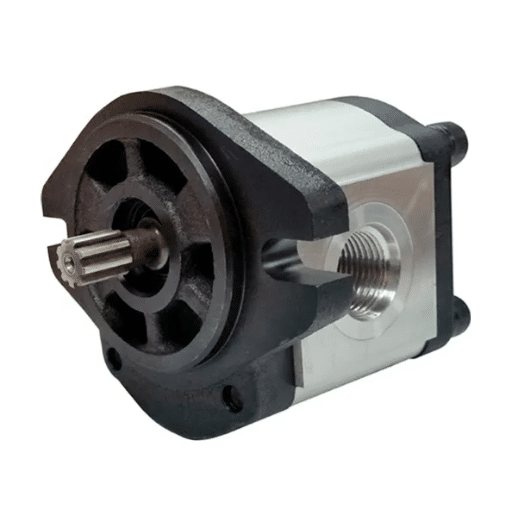
Mike Torres ran a twelve-truck construction fleet outside Columbus, Ohio. Over six months, his shop replaced three hydraulic pumps at nearly $1,400 each. Every replacement worked for a few weeks, then failed again with the same symptoms: slow lift, overheating, and noisy operation. The fourth technician finally pulled a fluid sample and sent it to a lab. The report came back with a contamination rating of ISO 22/20/17, far above the acceptable ISO 18/16/13 limit. Dirt and water in the hydraulic fluid had destroyed every new pump within weeks. Mike spent over $4,200 on pumps when a $280 fluid flush and filter replacement would have fixed the root cause.
If you manage a fleet, operate a repair shop, or specify a hydraulic pump for a dump truck, this scenario is painfully familiar. Dump truck hydraulic pump failures rarely happen in isolation. A failing pump is usually the symptom, not the disease. Contaminated fluid, incorrect sizing, mismatched PTO ratios, and overlooked wet kit configurations all produce identical failure patterns. Replace the pump without fixing the system, and you will replace it again.
In this guide, you will learn how dump truck hydraulic pumps work within the complete dump truck hydraulic system architecture, how to select the right pump technology for your application, how dump truck wet kit configurations affect performance, and how fleet operators can build maintenance schedules that prevent the $4,200 mistake Mike Torres made. By the end, you will have a framework for specifying, troubleshooting, and sourcing hydraulic components that last.
Need a hydraulic pump specification review or bulk fleet quotation? Contact our engineering team for a compatibility assessment and customized procurement recommendation.
How Dump Truck Hydraulic Pumps Work

A dump truck hydraulic pump converts mechanical energy from the engine into hydraulic pressure that raises and lowers the dump bed. The system operates on Pascal’s Law: pressure applied to a confined fluid transmits equally in all directions. This principle allows a relatively small pump to generate enough force to lift loads from 5 to over 80 tons.
The typical power flow follows this path. The engine turns the transmission, which drives a Power Take-Off (PTO) unit. The PTO spins the hydraulic pump at a fixed ratio, typically 1,500 to 1,800 RPM during lifting. The pump draws fluid from the reservoir and pressurizes it. Pressurized oil flows through a control valve, which directs it into the hydraulic cylinder. The cylinder extends, raising the bed. When the operator releases the control, the valve redirects fluid back to the reservoir, and the bed lowers by gravity or powered descent, depending on the wet kit configuration.
Pressure and Flow Relationship
Pressure and flow are independent but related variables in a hydraulic system. The pump generates flow (measured in gallons per minute or liters per minute). The load resistance creates pressure (measured in PSI or MPa). A pump moving fluid against a heavy load generates high pressure. The same pump moving fluid through an open return line generates almost no pressure.
This distinction matters for diagnostics. A pump that produces adequate flow but low pressure usually indicates internal wear or relief valve malfunction, not pump failure. Conversely, a pump that generates high pressure but slow cylinder movement indicates a flow restriction, possibly a clogged filter or undersized hose.
System Efficiency Considerations
Traditional fixed-displacement pumps run at full flow regardless of demand, wasting energy as heat when the cylinder reaches its mechanical limit. Modern load-sensing pumps adjust output based on real-time demand, reducing energy consumption by approximately 27% according to 2025 market data. For fleets operating hundreds of cycles per day, this efficiency gain translates directly into lower fuel costs and reduced cooling system load.
Key Components of a Dump Truck Hydraulic System
Understanding each component’s role helps diagnose failures and specify replacements correctly. A dump truck hydraulic system contains seven core elements that must work in concert.
The Hydraulic Pump
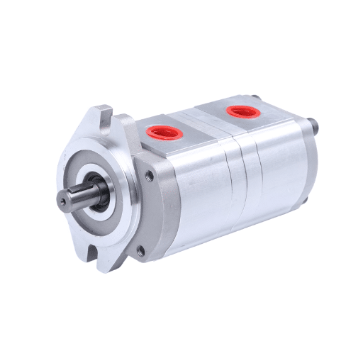
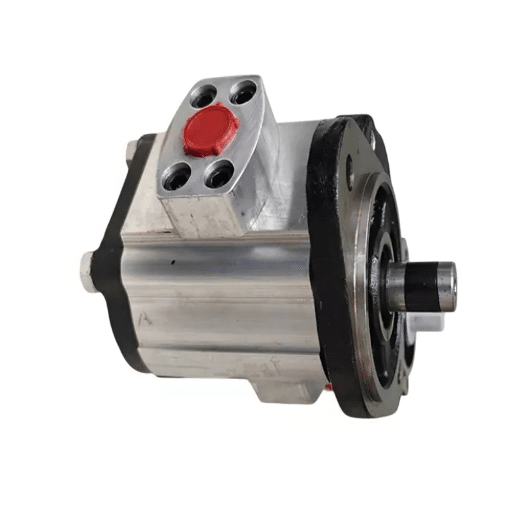
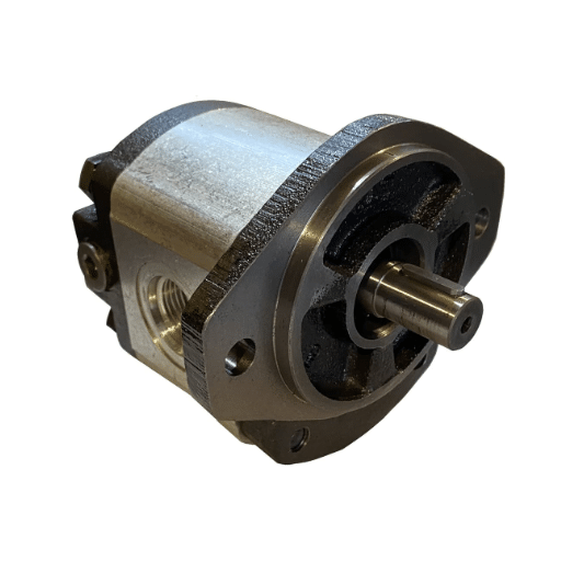
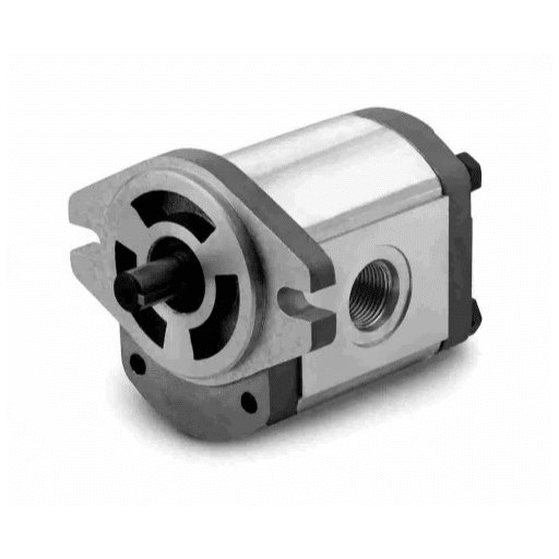
The pump is the heart of the system. Gear pumps dominate light and medium duty applications due to their simple construction, reliability, and lower cost. Piston pumps serve heavy duty and mining applications where higher pressure and variable displacement improve efficiency. The pump’s flow rate, measured in GPM or L/min, must match the cylinder volume and desired cycle time.
Power Take-Off (PTO)
The PTO mounts to the truck transmission and provides the mechanical interface between engine and pump. PTO selection determines pump speed, which directly affects flow output. An incorrectly matched PTO ratio causes the pump to run too fast (cavitation and premature wear) or too slow (sluggish lift times). PTO engagement types include air-shift, cable-operated, and electric configurations.
For PTO selection guidelines and installation procedures, see our dump truck PTO hydraulic pump guide.
Hydraulic Cylinder
The cylinder converts hydraulic pressure into the mechanical force that lifts the dump bed. Telescopic cylinders dominate heavy duty trucks because they provide long stroke in a compact package. Single-stage cylinders serve lighter applications. Cylinder bore diameter and rod diameter determine lifting capacity.
For detailed cylinder selection criteria, see our dump truck hydraulic cylinder guide.
Control Valve
The directional control valve manages fluid routing. Manual valves use cable or lever actuation. Electro-hydraulic valves integrate with truck electronics for automated operation. Relief valves protect the system from over-pressurization, typically set 10-15% above normal operating pressure.
Hydraulic Reservoir
The reservoir stores fluid, dissipates heat, and allows air to separate from the oil before recirculation. Capacity should equal two to three times the pump’s flow rate per minute. An undersized reservoir causes overheating because the fluid does not have enough dwell time to cool between cycles.
Hoses and Fittings
High-pressure hoses rated for at least 1.5 times the maximum system pressure prevent catastrophic failures. Common dump truck systems use 1-inch to 1.5-inch hoses rated for 3,000 to 4,000 PSI. Hose routing must avoid sharp bends, abrasion points, and heat sources.
Filters
Suction filters protect the pump from large contaminants. Return line filters clean fluid before it re-enters the reservoir. Pressure filters on the pump outlet catch fine particles that would damage the control valve and cylinder seals. A 10-micron return filter and 25-micron pressure filter provide adequate protection for most dump truck applications.
For a deep dive into wet kit selection, see our dump truck wet kit configuration guide.
Gear Pump vs Piston Pump: Choosing the Right Technology
Selecting the wrong pump technology is one of the most expensive specification errors in dump truck hydraulics. Gear pumps and piston pumps serve different duty cycles, pressure ranges, and cost structures.
| Feature | Gear Pump | Piston Pump |
|---|---|---|
| Operating pressure | 14-21 MPa (2,000-3,000 PSI) | 21-45 MPa (3,000-6,500 PSI) |
| Flow efficiency | 80-85% | 90-95% |
| Cost per unit | Lower | Higher |
| Maintenance complexity | Simple | Moderate |
| Noise level | Moderate | Lower |
| Variable displacement | No (fixed) | Yes (available) |
| Typical application | Light/medium duty, general hauling | Heavy duty, mining, high cycle |
| Market share (2025) | 47.2% | Growing in premium segments |
Gear pumps hold 47.2% of the truck hydraulic pump market as of 2025. Their cost advantage and mechanical simplicity make them the default choice for fleets operating standard dump trucks up to 30 tons. However, gear pumps cannot match the efficiency of load-sensing piston pumps in applications with variable demand.
Piston pumps justify their higher cost in three scenarios. First, mining and heavy construction trucks that operate 200+ lift cycles per day benefit from the energy savings of variable displacement. Second, applications requiring precise flow control, such as trucks with multiple hydraulic functions beyond dumping, need the controllability that piston pumps provide. Third, OEMs building premium truck lines increasingly specify piston pumps to meet emissions and fuel efficiency targets.
For a detailed engineering comparison of dump truck applications specifically, see our gear pump vs piston pump analysis.
Power Take-Off (PTO) Systems for Dump Trucks

The PTO is often the most overlooked component in a dump truck hydraulic system, yet it determines dump truck PTO hydraulic pump speed, engagement reliability, and overall system efficiency.
Transmission-Mounted PTOs
Most dump trucks use transmission-mounted PTOs that engage through a gear interface with the transmission’s countershaft. These PTOs provide direct, efficient power transfer. The PTO ratio, expressed as engine speed to PTO output speed, typically ranges from 0.8:1 to 1.4:1 depending on transmission model.
PTO Ratio Selection
Pump manufacturers specify optimal operating speed, usually 1,500 to 1,800 RPM for gear pumps. To calculate the required PTO ratio, divide the pump’s rated speed by the engine’s typical operating RPM during lifting. For example, a pump rated at 1,800 RPM driven by an engine running at 1,200 RPM during lift requires a 1.5:1 PTO ratio.
An incorrect ratio produces two common problems. If the PTO over-speeds the pump, cavitation occurs at the pump inlet. The pump draws fluid faster than the reservoir can supply it, creating air bubbles that implode inside the pump and erode internal surfaces. If the PTO under-speeds the pump, lift times increase beyond acceptable limits, and the pump may not generate enough flow to operate the control valve correctly.
Engagement Types
Air-shift PTOs use pneumatic pressure to engage the drive gear. They offer reliable operation and integrate easily with truck air systems. Cable-operated PTOs provide mechanical simplicity but require periodic cable adjustment as the linkage wears. Electric PTOs offer the most flexible integration with modern truck electronics, but add complexity and potential failure points. Choosing the correct engagement type is essential for any dump truck PTO hydraulic pump installation because mismatched controls are a leading cause of premature drivetrain wear.
Wet Kits Explained: Single, Dual, and Three-Line Systems
A dump truck wet kit is the complete hydraulic system installed on a truck chassis, including the PTO, pump, reservoir, valve, hoses, and cylinder. The term distinguishes these systems from dry kits, which lack the hydraulic components and require separate installation.
Single-Line Wet Kits
Single-line systems use one pressure line from the pump to the cylinder and rely on gravity to lower the bed. A check valve holds the cylinder extended until the operator opens the control valve, allowing fluid to return to the reservoir. These systems are the simplest and least expensive configuration.
The limitation is control. Gravity lowering is fast and cannot be regulated easily. Single-line systems work well for light duty applications where precise lowering speed is not critical. They also require a larger reservoir because fluid returns slowly and may cause foaming.
Dual-Line Wet Kits
Dual-line systems add a dedicated return line from the cylinder back to the reservoir, enabling powered lowering. The control valve directs pressurized fluid to either side of the cylinder piston, providing controlled raise and lower speeds. This configuration improves safety and allows operators to feather the bed down onto uneven loads.
Most medium duty dump trucks use dual-line wet kits because they balance cost and control. The additional hose and valve complexity adds approximately 15-20% to system cost compared to single-line configurations.
Three-Line Wet Kits
Three-line systems provide independent raise and lower circuits with a dedicated pilot line or separate tank return. These configurations support the fastest cycle times and highest flow rates. Heavy duty mining trucks and high-volume construction fleets specify three-line systems because they minimize downtime between loads.
In 2026, CS Trucks demonstrated an optimized 80-ton mine system using intelligent converging valve architecture. The system achieved 19.5-second lift times compared to 25 seconds for traditional configurations, a 22% improvement. Energy consumption dropped 15.1%, and vibration amplitude fell 40% due to electronic pilot-controlled hoist valves with cushioning.
Hydraulic Cylinders: Telescopic vs Single-Stage
The hydraulic cylinder is the muscle of the dump truck’s hydraulic system. Cylinder selection directly affects lifting capacity, stability, and maintenance frequency.
Telescopic Cylinders
Telescopic cylinders contain multiple nested stages that extend sequentially. Each stage has a smaller diameter than the one before it, allowing long stroke in a compact retracted length. A typical five-stage cylinder for a heavy duty dump truck might provide 180 inches of stroke while retracting to only 48 inches.
The force output changes as each stage extends. The first stage, with the largest bore diameter, produces the highest force for initial lift when the bed is horizontal and heaviest. Subsequent stages, with smaller diameters, provide less force but greater extension for the final dump angle. This staged force profile matches the mechanical advantage requirements of dump bed geometry.
Single-Stage Cylinders
Single-stage cylinders use one piston and rod assembly. They are simpler, less expensive, and easier to seal than telescopic designs. However, their extended length equals their stroke length, requiring more chassis space. Single-stage cylinders suit light duty dump trailers and smaller trucks where space is not constrained.
Seal Technology and Maintenance
Cylinder seals prevent fluid leakage past the piston and rod. Polyurethane seals dominate modern applications due to their wear resistance and compatibility with synthetic hydraulic fluids. Viton seals handle higher temperatures up to 121 °C but cost more. Fleet operators should inspect rod seals weekly for scoring, contamination, and leakage. A leaking seal allows dirt to enter the cylinder during retraction, accelerating wear on the bore and piston.
For cylinder specification and seal replacement guidance, see our dump truck hydraulic cylinder guide.
Common Pump Failure Symptoms and System Troubleshooting

Diagnosing hydraulic pump failures requires looking at the entire system, not just the pump. The same symptom can indicate multiple root causes. For a full diagnostic workflow, see our dump truck hydraulic pump troubleshooting guide.
Slow or Weak Lifting
Slow lift is the most common complaint. Check these causes in order: low fluid level, clogged suction filter, incorrect fluid viscosity, worn pump internals, and internal cylinder leakage. A pump producing normal pressure but low flow usually has worn gears or pistons. A pump producing low pressure usually has a stuck relief valve or excessive internal clearance.
Bed Drops Unexpectedly
If the dump bed lowers by itself when the control valve is in neutral, suspect the cylinder seals, check valve, or control valve spool. Cylinder seal failure allows fluid to bypass the piston internally. A stuck check valve fails to hold pressure in the raise port. A worn control valve spool allows fluid to leak across ports.
Noisy Pump Operation
A whining or screaming pump usually indicates cavitation. Check the suction line for restrictions, the reservoir fluid level, and the fluid temperature. Hot fluid has lower viscosity and may not fill the pump inlet fast enough. Air entering the suction line through loose fittings produces a distinct rattling noise.
Overheating
Normal hydraulic system operating temperature ranges from 49℃ to 71℃. Temperatures above 82℃ accelerate fluid degradation and seal failure. Overheating causes include undersized reservoir, continuous operation without cooling periods, blocked heat exchanger, and excessive relief valve bypass.
For repair procedures and component replacement guidance, see our dump truck hydraulic pump repair guide.
| Symptom | Likely Cause | First Diagnostic Step |
|---|---|---|
| Slow lift | Low fluid, clogged filter, worn pump | Check fluid level and condition |
| Bed drops | Internal leak, bad check valve | Test cylinder hold pressure |
| Noisy pump | Cavitation, air leak | Inspect suction lines and fluid level |
| Overheating | Undersized reservoir, continuous use | Measure reservoir temperature |
| Jerky motion | Air in system, contaminated fluid | Bleed air, check fluid cleanliness |
| No lift | Dead pump, broken PTO, low fluid | Verify PTO engagement and fluid |
Sizing and Selecting a Hydraulic Pump for Your Application
Correct hydraulic pump for dump truck sizing prevents the two most common specification errors: undersizing, which causes slow lift and overheating, and oversizing, which wastes energy and increases cost.
GPM Sizing Formula
Calculate required pump flow using the cylinder volume and desired cycle time:
GPM = (Cylinder volume in cubic inches x Cycles per minute) / 231
For a dump truck cylinder with 500 cubic inches of volume and a target lift time of 20 seconds (3 cycles per minute):
GPM = (500 x 3) / 231 = 6.5 GPM
Add 10-15% margin for system losses and aging components. Specify a pump rated for approximately 7.5 GPM.
Pressure Matching
Match the pump’s rated pressure to the cylinder’s working pressure. Light duty dump trailers operate at 14-17 MPa (2,000-2,500 PSI). Medium duty dump trucks use 17-21 MPa (2,500-3,000 PSI). Heavy duty mining trucks may require 25-28 MPa (3,600-4,000 PSI). Always specify a pump with a rated pressure at least 10% above the system’s normal operating pressure.
Reservoir Sizing
The reservoir should hold two to three times the pump’s flow rate per minute. For a 10 GPM pump, specify a 20-30 gallon reservoir. This ratio provides adequate dwell time for air separation and heat dissipation. An undersized reservoir causes rapid fluid overheating and foam formation.
Worked Example
Consider a 10-yard dump truck with a telescopic dump truck hydraulic cylinder requiring 600 cubic inches of fluid for full extension. The fleet requires a 15-second lift time, meaning 4 cycles per minute.
GPM = (600 x 4) / 231 = 10.4 GPM
With 15% margin: 12 GPM pump
Operating pressure: 20 MPa (2,900 PSI)
Reservoir: 25-30 gallons
Fluid: ISO VG 46 anti-wear hydraulic oil
For dump trailer pump sizing specifically, see our hydraulic pump for dump trailer guide.
Maintenance Schedule for Fleet Operations
Preventive maintenance is the difference between a hydraulic system that lasts ten years and one that fails every six months. The following schedule applies to typical dump truck fleets operating in construction or mining environments. For a complete fleet maintenance schedule, see our dump truck hydraulic system maintenance guide.
Daily Inspections
Check the hydraulic fluid level in the reservoir. Low fluid indicates a leak that must be addressed before operation. Inspect hoses and fittings for leaks, abrasions, and loose connections. Check cylinder rods for scoring, pitting, or contamination before retracting.
Weekly Tasks
Clean the exterior of the hydraulic reservoir and inspect the breather cap for contamination. Check filter condition indicators if equipped. Listen for unusual pump noise during lift cycles. Verify PTO engagement and disengagement operate smoothly.
Monthly Procedures
Inspect cylinder seals for leakage. Check pump mounting bolts and PTO fasteners for proper torque. Test relief valve operation by briefly overloading the system and verifying the valve opens at set pressure. Inspect suction strainer and clean if necessary.
Annual Overhaul
Replace all hydraulic fluid and filters. Send a fluid sample to a laboratory for particle count analysis. The ISO cleanliness code should not exceed 18/16/13. Inspect cylinder bores for scoring and measure piston clearances. Replace worn seals and O-rings. Test pump flow and pressure against manufacturer specifications.
Operating in extreme conditions? Contact our engineering team for a customized maintenance interval schedule based on your duty cycle and environment.
OEM vs Aftermarket: Procurement Guide for Fleet Managers

Fleet managers face a constant tension between OEM warranty compliance and aftermarket cost savings. The right decision depends on equipment age, fleet size, and standardization strategy.
Cost Comparison
OEM hydraulic pumps typically cost 40-100% more than equivalent aftermarket units. For a standard gear pump rated at 15 GPM and 21 MPa, OEM pricing might range from 800 to 1,400, while a quality aftermarket replacement ranges from 450 to 800. The price gap widens for premium brands like Parker or Bosch Rexroth.
When OEM Is Essential
Specify OEM pumps when the truck is under warranty, when the fleet operates under OEM service contracts, or when the manufacturer requires OEM components for emissions or safety certifications. OEM compatibility documentation also simplifies warranty claims when downstream components fail.
When Aftermarket Makes Sense
Aftermarket pumps provide equivalent performance for equipment outside warranty coverage. They also allow fleet standardization across mixed truck brands. A construction fleet operating Kenworth, Peterbilt, and Freightliner trucks can standardize on one aftermarket pump model that meets all three applications, reducing inventory complexity and technician training requirements.
In 2024, a construction equipment rental company with forty mixed-model skid steers and excavators consolidated its hydraulic component sourcing through a single industrial supplier. Previously, they carried seventeen different pump and cylinder part numbers across three brands. After standardizing on a supplier with broad cross-reference data, they reduced inventory to six part numbers. Diagnostic time dropped because technicians no longer had to cross-reference multiple catalogs. Warranty returns also fell because the standardized components met or exceeded OEM pressure and flow specifications.
For all-in-one pump and motor assemblies, see our dump truck hydraulic power unit guide.
Supplier Vetting Checklist
Before sourcing aftermarket hydraulic pumps, verify these criteria:
- Pressure and flow ratings match or exceed OEM specifications
- Mounting dimensions and shaft configuration are compatible
- Materials match OEM standards (hardened steel gears, ductile iron housings)
- Supplier provides material certifications and test reports
- Warranty terms are comparable to OEM coverage
- Technical support is available for installation questions
For a brand-specific compatibility overview, see our HYVA hydraulic pump for dump trucks guide.
Frequently Asked Questions
Why is my dump truck bed not lifting?
Check fluid level first. Low fluid is the most common cause. Next, verify PTO engagement and pump operation. Listen for pump noise when the control is activated. If the pump runs but produces no pressure, check the relief valve setting and inspect for internal pump wear.
How often should I change hydraulic fluid in a dump truck?
Change hydraulic fluid annually or every 2,000 operating hours, whichever comes first. In severe environments with high dust or temperature extremes, change fluid every 1,000 hours. Always replace filters with every fluid change.
What is the difference between a wet kit and a dry kit?
A wet kit includes all hydraulic components pre-installed on the truck chassis: PTO, pump, reservoir, valve, hoses, and cylinder. A dry kit is a truck chassis without hydraulic components, requiring separate installation of the complete system. Wet kits reduce installation time and ensure component compatibility.
Can I use any hydraulic fluid in my dump truck pump?
No. Use ISO VG 46 anti-wear hydraulic oil for typical operating temperatures from -20 °C to 80 °C. Synthetic ester fluids rated for -40 °C to 121 °C are required for extreme cold environments. Never mix different fluid types, as additive packages can react and form sludge.
How long does a dump truck hydraulic pump last?
A properly maintained gear pump in a medium-duty application typically lasts 8,000 to 12,000 operating hours, or approximately 5-7 years in fleet service. Contaminated fluid, incorrect sizing, or continuous overloading can reduce the lifespan to 2,000 hours or less. Load-sensing piston pumps in optimized systems can exceed 15,000 hours with proper maintenance.
Conclusion and Fleet Specification Checklist
Dump truck hydraulic pump selection and maintenance demand a system-level perspective. The hydraulic pump for a dump truck does not operate in isolation. Its performance depends on dump truck PTO hydraulic pump ratio matching, dump truck wet kit configuration, dump truck hydraulic cylinder compatibility, fluid cleanliness, and reservoir sizing within the broader dump truck hydraulic system. Fleet managers who treat the pump as one component within an integrated system reduce failures, extend component life, and avoid the costly misdiagnosis pattern that cost Mike Torres over $4,200.
Key takeaways from this guide:
- Match pump technology to duty cycle: gear pumps for light/medium duty, piston pumps for heavy duty and high cycle counts
- Size pumps using the GPM formula with 10-15% margin for system losses
- Verify PTO ratios to prevent pump overspeed and cavitation
- Select wet kit configuration based on control requirements: single-line for simplicity, dual-line for controlled lowering, three-line for maximum cycle speed
- Maintain fluid cleanliness at ISO 18/16/13 or better to prevent premature pump and seal failure
- Standardize aftermarket components across mixed fleets to reduce inventory and simplify diagnostics
- Follow a structured maintenance schedule: daily inspections, weekly checks, monthly procedures, annual overhauls
Accurate hydraulic system specification protects the entire fleet. The time invested in proper sizing and preventive maintenance saves far more than the cost of emergency repairs and unnecessary component replacement. Whether you are specifying a new dump truck hydraulic pump, upgrading a dump truck wet kit, or sourcing a replacement dump truck hydraulic cylinder, a system-level approach ensures reliable performance and lower total cost of ownership.
Ready to source dump truck hydraulic pumps tested to OEM specifications? Contact LOYAL INDUSTRIAL PTE. LTD. today for a customized pump quotation, technical compatibility review, or bulk fleet supply agreement.