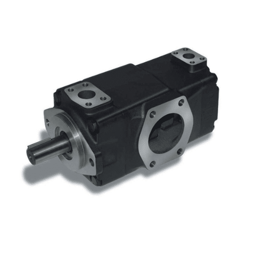
Ravi thought his vane pump sizing was finished. Every number matched: same flow as the tired gear pump he was replacing, same mounting flange, same port positions. Within a week, the machine was losing prime at start-up, and the pump was blamed for it.
The pump was fine. The problem was the drive. The old gear pump had tolerated the slow PTO at 500 rpm; the vane pump could not, because its vanes only seat against the cam ring once centrifugal force pushes them out. Nobody had checked the minimum speed, and that number was not on the flow-versus-pressure sheet where Ravi was looking.
That is what makes vane pump sizing different from sizing a pump in general. The arithmetic is standard. The constraints are not.
This guide walks the six steps in order, adds the three checks that only apply to vane pumps, and works two examples end to end in both US and metric units. If you are still choosing between pump families, our complete guide to hydraulic vane pumps covers the types and specifications first.
Working through a selection now? Request the vane pump specification sheet, and we will verify displacement, speed, and pressure margin against your duty cycle.
What Sizing a Hydraulic Vane Pump Actually Means

Sizing a hydraulic vane pump means matching four numbers to a duty cycle, then verifying two constraints that are specific to the vane design before you order.
Definition: vane pump sizing is the process of converting required circuit flow and system pressure into a pump displacement, landing on a standard frame size, and sizing the drive, while verifying the minimum speed for vane extension and the fluid viscosity window.
The four numbers are required flow in GPM or L/min, system pressure in PSI or bar, displacement in in³/rev or cm³/rev, and drive power in HP or kW. Get those right, and the pump is functionally correct.
The two extra checks are what separate a vane selection from a generic one. Vane pumps need roughly 600 to 900 rpm before the vanes extend and the pump primes; they tolerate a narrower viscosity window than gear pumps, and their volumetric efficiency differs from the figure most sizing guides print.
One point of terminology before the steps. The pump creates flow; system resistance converts that flow into pressure. A pump does not have a pressure of its own. Almost every sizing error traced back to a bad assumption starts with that confusion.
The generic method across all pump families lives in our hydraulic pump sizing guide. This article assumes that method and layers the vane-specific constraints on top of it.
Step 1: Find the Flow Your Circuit Needs
Flow comes from the actuator, never from the pump. Start with what has to move and how fast, then work back.
For a cylinder, the volume per stroke is bore area multiplied by stroke. Divide that by the cycle time you need, and you have the flow.
Why the Retract Stroke Surprises People
A double-acting cylinder acts on the full bore area when it extends, but only on the annulus when it retracts. The annulus is the bore area minus the rod area, so it is always smaller.
At the same flow, the cylinder retracts faster than it extends. A sizing that only checks extension is half-checked, and on a machine with a long rod the difference is not small. Calculate both directions and size to the higher flow requirement.
Vane Pump Flow Rate Formula and a Quick Check
For a 100 mm bore cylinder with a 250 mm stroke that must extend in 1.5 seconds:
- Bore area = π × 0.05² = 0.00785 m²
- Stroke volume = 0.00785 × 0.25 = 0.00196 m³ = 1.96 L
- Required flow = 1.96 ÷ 1.5 = 1.31 L/s = 78.5 L/min
In US units, a 4 in bore with a 10 in stroke extending in 1.5 seconds needs about 21.6 in³ per stroke, or roughly 5.6 GPM. Rotary actuators and hydraulic motors work the same way: displacement per revolution multiplied by the speed you need.
Step 2: Convert Flow to Displacement and Land on a Real Frame
This is the vane pump displacement calculation, and it has two stages. First, correct the flow for efficiency, then divide by drive speed.
Vane Pump Displacement Calculation
The theoretical flow a pump must generate is the required flow divided by volumetric efficiency. We define that efficiency value in Step 3, but the formula order matters, so correct the flow first.
- Metric: cm³/rev = (L/min × 1000) ÷ rpm
- US: in³/rev = (GPM × 231) ÷ rpm
A 4-pole electric motor runs at 1,450 or 1,750 rpm, so the drive speed is usually fixed by the motor you intend to use. That is why you convert flow to displacement at a known speed rather than choosing a displacement first. Choosing displacement first is the most common sequencing error in vane pump sizing.
The Geometry Behind the Number
If you are designing or rebuilding rather than buying from a catalogue, offset displacement comes from eccentricity. For a single-acting vane pump:
V_D = (π/2)(D_c + D_R) · e · L
where D_c is cam ring diameter, D_R is rotor diameter, e is eccentricity, and L is vane width. Maximum eccentricity is (D_c − D_R) ÷ 2, and at zero eccentricity there is no flow at all.
That derivation, including the two-lobe geometry of a double-acting pump, belongs with the working principle. Our guide to how a vane pump works covers it; the universal hydraulic pump displacement formula covers the concept across families.
Land on a Standard Frame
Catalogue displacement is quoted in cm³/rev, so convert your calculated figure to a real frame rather than stopping at a decimal. Most industrial duties fall into recognisable bands.
| Machine class | Typical displacement | Typical pressure |
|---|---|---|
| Compact machines, power steering, small power units | 7 to 20 cm³/rev | 70 to 140 bar |
| Injection moulding, die-casting, machine tool clamping | 20 to 45 cm³/rev | 140 to 210 bar |
| Heavy presses, large central power units | 45 cm³/rev and above | 140 to 210 bar |
Single-acting variable vane pumps span roughly 6 to 120 mL/r. Fixed double-acting pumps cover a wider range, commonly 2.5 to 300 mL/r in industrial series.
One warning before you commit. If the duty includes long hold phases at pressure with little or no flow, a fixed-displacement pump is the wrong starting point, and the selection changes entirely. That decision belongs to variable displacement vane pumps, and we cover it there rather than here.
Step 3: Use the Right Vane Pump Volumetric Efficiency

Most sizing guides print a single efficiency band of 85 to 95% and apply it to every pump family. For a vane pump that is imprecise in both directions.
Vane volumetric efficiency: roughly 92% for a single-acting vane pump and above 94% for a double-acting design at rated conditions, against a typical overall efficiency near 85% once mechanical losses are included.
That is higher than a gear pump typically delivers, and the reason is the hydraulic balance and precision clearances of the vane design. The same tight clearances are why filtration and viscosity matter so much to this family.
Slip rises as pressure rises and falls as viscosity rises. The practical consequence is that you should size at your maximum continuous pressure, not at the relief valve set point alone, because efficiency at the working pressure is the number that governs real flow.
There is a second-order correction worth knowing. Vane thickness slightly reduces swept volume, by about 1.7% in a 17-vane rotor and 2.9% in a 13-vane rotor. It is small enough to ignore in most selections, but it is real when a specification sits on a frame boundary.
Step 4: Check the Vane Pump Pressure Rating
Pressure is imposed by system resistance, so calculate it from the maximum load the machine must move, not from a target you would like. Then check it against the pump rating, and here the discipline is to compare like with like.
A vane pump carries three ratings: continuous, intermittent, and peak. The selection must be made on the continuous rating at your maximum system pressure. Selecting on the peak figure is how a pump reaches the end of its life in months rather than years.
Pressure Ceilings by Design
The vane family does not have one pressure ceiling. It has several, and they depend on construction:
- Single-acting, variable designs sit lower, classically around 6 to 7 MPa, with modern variable families reaching 100 bar direct-controlled, 160 bar pilot-operated, and 250 bar in the highest-rated designs.
- Double-acting, fixed designs reach higher because the balanced geometry cancels the radial shaft load. Industrial series typically run 175 to 210 bar, with claims to 28 to 30 MPa on some designs.
- Cam-rotor designs sit around 21 MPa.
Cross-brand series data shows the spread clearly. Parker’s T6*R catalogue rates the Denison T6/T7 series at 320 bar in their smallest frames, while Vickers V/VQ and Yuken PV2R reach about 210 bar. Tokimec SQP reaches about 175 bar. Eaton VSO/V fixed industrial pumps run 280 bar continuously with a 310 bar peak, and the Parker T series is rated to 140 bar at the outlet.
The Insight That Catches Procurement Buyers
Within a single series, the largest displacement usually carries the lowest continuous pressure rating. A series headline of 250 bar may apply only to the smallest frames.
Confirm the continuous rating at the frame size you actually selected. Our guide to double-acting vane pumps explains why the balanced geometry earns the higher ceiling in the first place.
Above roughly 210 bar continuous on an industrial duty, the vane family stops being the right answer. That is a piston pump duty, and recommending the change is more useful than defending the wrong pump.
Step 5: Verify the Vane Pump Minimum Speed
This is the constraint that decides more vane selections than any other, and the one Ravi’s flow-versus-pressure sheet never mentioned.
Vanes are thrown outward against the cam ring by centrifugal force. Below a certain rotor speed, they do not seat, the pump does not prime, and it will not build pressure. This rule does not apply in the same way to gear or piston pumps.
Documented Speed Windows
The general minimum is often quoted at 600 to 900 rpm, but treat that as a starting band rather than a fixed law, because the real floor depends on the design and the oil.
- Parker T6DR: 600 to 2,800 rpm, and it holds 600 rpm at full pressure.
- Parker T6R: down to 400 rpm under low pressure with 2,000 cSt oil.
- OXIM PVL series: 600 to 1,800 rpm, with the smaller PVL1 frames at 750 to 1,800 rpm.
Typical running speed is 1,500 to 2,000 rpm. Small double-acting designs can reach 8,000 to 10,000 rpm, and single-acting variable designs generally top out near 3,000 rpm.
The Speed Gate as a Selection Decision
Express the floor as a check against the prime mover. A 4-pole motor at 1,450 or 1,750 rpm clears it with margin. A slow engine PTO, a low-speed hydraulic motor, or a variable-speed drive running below 600 rpm does not.
When the drive cannot clear the floor, that is a family-change decision, not a pump-change decision. Size a gear pump instead.
The maximum side matters too. Eaton warns against running a vane pump at or near rated pressure at idle speeds for extended periods, because localised overheating damages the pump.
Inlet Conditions Belong Here
Inlet design interacts with speed, so check it in the same pass. Vane pumps should not have an inlet strainer, because the resulting pressure drop causes cavitation. If a strainer is unavoidable, use 250 µm or coarser and verify the pressure drop.
Keep inlet velocity at or below about 1.9 m/s and discharge velocity at or below about 6.0 m/s.
Step 6: Vane Pump Motor Sizing: Power, Torque and Service Factor

Hydraulic power is the flow multiplied by the pressure, with a unit constant.
- Metric: kW = (L/min × bar) ÷ 600
- US: HP = (GPM × PSI) ÷ 1714
Divide that by overall efficiency to get shaft power, then apply a service factor of 1.15 to 1.20 for coupling losses and motor longevity.
Torque for a Directly Coupled Drive
If you are matching an electric motor frame, torque matters as much as power. For a directly coupled drive:
T (N·m) = V_D (cm³/rev) × Δp (bar) ÷ 20π
The Shaft Rule That Kills Vane Pumps in the Field
Vane pumps accept no radial and no axial shaft load. No belt drives, no chain drives, no side loading of any kind. This is a sizing constraint, not an installation footnote, because the bearing arrangement in an unbalanced vane pump is already carrying the radial load the geometry creates.
If your drive concept needs a belt, the pump selection changes. Check the arithmetic against our hydraulic pump horsepower calculator as you work.
Two Worked Examples, Start to Finish
The formulas only become a selection when you run them against a real duty. Here are two complete vane pump sizing examples, in different unit systems and different machine classes.
Example A: US Units, Mobile Auxiliary Circuit
A compact machine needs 12 GPM at a maximum of 2,000 PSI, driven at 1,750 rpm from the engine.
Displacement. (12 × 231) ÷ 1,750 = 1.58 in³/rev before slip. Divide by 0.92 for volumetric efficiency: 1.72 in³/rev, or about 28 cm³/rev. Select the nearest standard frame.
Pressure check. 2,000 PSI is about 138 bar. That sits inside the 175 to 210 bar continuous band of a double-acting series, with margin.
Drive power. (12 × 2,000) ÷ 1,714 = 14.0 HP. Divide by 0.85 for overall efficiency: 16.5 HP. Apply a 1.20 service factor: about 20 HP.
Speed check. 1,750 rpm clears the 600 rpm floor comfortably.
Example B: Metric Units, Industrial Power Unit
Tomas is specifying the power unit for an injection-moulding clamp circuit. The cylinder needs 45 L/min at 140 bar, driven by a 1,450 rpm motor on clean, filtered oil.
Displacement. Correct the flow first: 45 ÷ 0.94 = 47.9 L/min theoretical. Then (47.9 × 1000) ÷ 1,450 = 33.0 cm³/rev. Select the nearest standard frame at about 33 cm³/rev.
Pressure check. 140 bar sits inside the 175 to 210 bar continuous band for a double-acting pump.
Drive power. (47.9 × 140) ÷ 600 = 11.2 kW. Divide by 0.85: 13.1 kW shaft. Apply a 1.15 service factor: a 15 kW motor.
Verification checks. 1,450 rpm clears the 600 rpm floor. Confirm continuous pressure at the chosen frame size, not at the series headline. Specify ISO VG 46 oil with 10 to 20 µm absolute filtration, and no inlet strainer.
| Example A (US) | Example B (metric) | |
|---|---|---|
| Required flow | 12 GPM | 45 L/min |
| System pressure | 2,000 PSI (138 bar) | 140 bar |
| Volumetric efficiency | 0.92 | 0.94 |
| Displacement selected | ~28 cm³/rev | ~33 cm³/rev |
| Drive power | ~20 HP | 15 kW |
| Speed check | 1,750 rpm, passes | 1,450 rpm, passes |
Both examples assume single-duty fixed displacement. Where a machine holds pressure for long periods without flow, the selection changes, and the variable-displacement case is covered separately.
Verify Mounting, Shaft, Ports and Rotation Before You Order

A correctly sized pump that will not fit or will not turn the right way is not a correct selection, so finish every vane pump sizing with an interface check.
Confirm the mounting flange and pilot, the bolt pattern, and whether the shaft is keyed or splined. Confirm rotation direction against the drive, because a unidirectional port plate fitted backwards will not work. Confirm port position and size, and check the case drain limit for the series, which is typically 1 to 2 bar.
Alignment tolerances are tight. Coupling concentricity should sit within 0.05 to 0.10 mm TIR, and the mounting face should be square to within 0.0381 mm/mm. Misalignment shows up first as noise, then as a bearing failure.
Fitting a vane pump to an existing machine? Send us the mounting detail, and we will cross-check it against the frame you selected.
Common Vane Pump Sizing Mistakes
Most failed selections trace back to a short list. Check each one before you commit.
- Choosing displacement before flow. The actuator defines the flow requirement, not the catalogue.
- Using a generic efficiency value. Vane pumps run at 92% single-acting and above 94% double-acting, not the 85 to 95% band printed for all families.
- Ignoring the minimum speed. The most expensive and most vane-specific error, and the one that produces a pump wrongly condemned as faulty.
- Selecting on peak pressure. Match the continuous rating at your chosen frame, not the series headline.
- Skipping the cold-start check. Vane pumps are the weakest family on cold, thick oil, so a cold-start review can change the displacement, the oil grade, or the family.
- Fitting an inlet strainer from habit. It causes cavitation on a vane pump. Avoid it, or use 250 µm coarser and verify the drop.
- Oversizing for comfort. Bigger is not safer. Excess flow goes over the relief as heat, at roughly 2.67 kW for every 10 L/min bypassed at 160 bar.
- Assuming a balanced pump can be made variable. It cannot. Variable flow requires a single-acting design.
The honest case matters as much as the positive one. If the drive cannot clear 600 rpm, if continuous pressure exceeds about 210 bar, or if the fluid cannot be held to 10 to 25 µm absolute, the correct recommendation is a different family.
Frequently Asked Questions
What does sizing a hydraulic vane pump involve?
It means matching required circuit flow and system pressure to a pump displacement and frame size, sizing the drive power, and then verifying the two vane-specific constraints: the minimum speed for vane extension and the fluid viscosity window. Flow comes from the actuator, and displacement follows from flow and drive speed.
How do I calculate vane pump displacement?
Divide theoretical flow by drive speed. In metric, cm³/rev equals L/min multiplied by 1000 and divided by rpm. In US units, in³/rev equals GPM multiplied by 231 and divided by rpm. Correct the required flow for volumetric efficiency before this step, not after.
What is the vane pump flow rate formula?
Theoretical flow is displacement multiplied by speed. In metric, L/min equals cm³/rev multiplied by rpm divided by 1000. In US units, GPM equals in³/rev multiplied by rpm divided by 231. Actual flow is theoretical flow multiplied by volumetric efficiency.
What is the minimum rpm for a vane pump?
Vanes are pushed against the cam ring by centrifugal force, so the rotor must turn fast enough to throw them out and seal. The general minimum is about 600 to 900 rpm, though documented frames vary from 400 to 750 rpm at the low end. Below that floor, the pump will not prime.
What vane pump volumetric efficiency should I use?
Use roughly 92% for a single-acting vane pump and above 94% for a double-acting design at rated conditions. These are higher than typical gear pump values. Size at your maximum continuous pressure, because slip increases with pressure and reduces real flow.
How much horsepower do I need to drive a vane pump?
Hydraulic power is (GPM × PSI) ÷ 1714, or (L/min × bar) ÷ 600 in metric. Divide that by overall efficiency, near 85%, then apply a 1.15 to 1.20 service factor. A 12 GPM pump at 2,000 PSI therefore needs roughly 20 HP at the drive.
How do I know if a vane pump is the wrong choice?
Three conditions rule it out. If the prime mover cannot clear about 600 rpm, if continuous pressure exceeds roughly 210 bar, or if the fluid cannot be held to 10 to 25 µm absolute filtration, the vane family is the wrong answer and a gear or piston pump fits better.
Getting Vane Pump Sizing Right the First Time
Vane pump sizing reduces to six steps, and only the last three are genuinely specific to the family:
- Find the flow the actuator needs, in both directions.
- Correct it for volumetric efficiency and convert to displacement at drive speed.
- Apply a vane efficiency value, not a generic one.
- Check continuous pressure at the frame you selected.
- Verify the minimum speed against the prime mover.
- Size the drive power and torque, with a 1.15 to 1.20 service factor.
Two of those steps are gates rather than calculations. The 600 rpm floor and the continuous pressure rating at your chosen frame are where most selections succeed or fail, and both are easy to miss on a flow-versus-pressure sheet.
Anders learned that the second way. He sized a pump one frame above requirement because it looked like a safer buy. The extra flow went over the relief valve all day, and the oil temperature rose until seals started failing early. The oversize pump cost more to buy and more to run, with no reliability gain at all.
Sizing to the number, with a stated margin, beats sizing by feel every time.
If you would rather verify a hydraulic vane pump selection than defend one, our engineering team reviews duty cycles against frame data, pressure margin, and the speed check. Contact us for a hydraulic system consultation or request a specification sheet for the frame you have landed on.