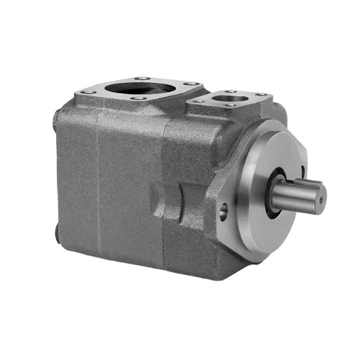
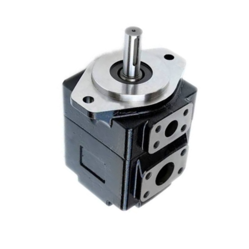
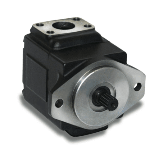
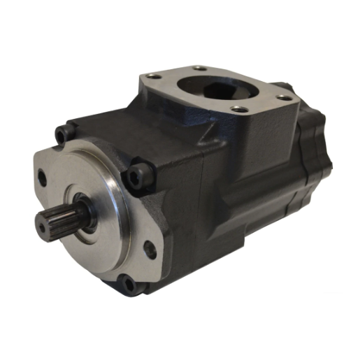
A triple vane pump is not rated as one pump. It is rated three times, once per outlet, and the three numbers are rarely equal.
That single fact causes most specification errors and almost all false diagnoses on this family. A buyer compares a quoted triple against a competitor’s headline pressure, buys the bigger number, and later finds the cover-end circuit was never rated for it. A fitter sees one circuit go weak, tests the main outlet, reads normal, and replaces a relief valve that was working.
This article covers the three parts of the job the catalogue leaves out: what each port is rated for, how to find which section has failed, and how to order the right kit. For the architecture, section order, or displacement-ratio method, see how double and triple vane pumps are configured.
Key Takeaways
- A triple vane pump carries a separate continuous and intermittent rating for P1, P2 and P3. The port at the cover end, P3, is usually rated lowest.
- Multi-section units derate versus the same pump sold as a single. A T6 frame listed at 320 bar alone is often published near 300 bar once three share the casting, and the D frame about 280 to 250 bar.
- When one circuit goes weak, the fault is a cartridge, a support plate, a relief setting or the circuit, and the sequence below separates them without removing the pump.
- A triple pump needs three cartridge kits. The model code tells you which kit belongs to which section.
- Confirm every figure on this page against the OEM catalogue for your exact model before you order or set a relief.
What makes a triple vane pump different
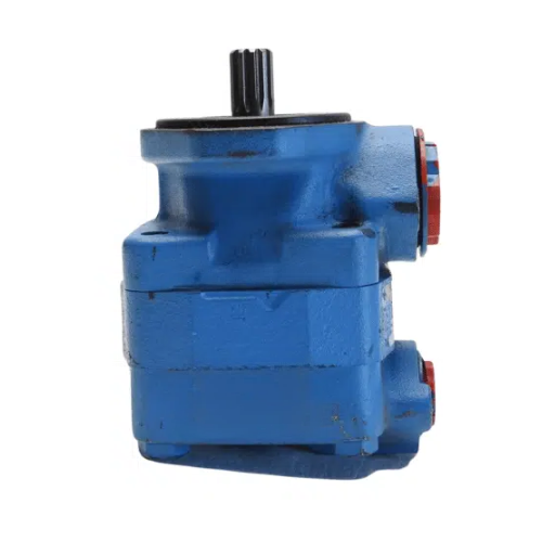
Three cartridges sit in one housing on one shaft. They share the suction port, the housing, the shaft, and the oil; they do not share flow, pressure, or outlet. Each cartridge is self-contained (rotor, vanes, cam ring, port plates and seals) and discharges through its own port.
The shared parts are where the constraints come from. One shaft carries the sum of three torques. One housing carries the combined radial and thermal load of three pumping elements. One sump means one contamination event reaches all three sections at once. Everything below follows from that: why the ratings differ by port, why one fault can mimic another, and why the kits are sold separately.
Triple vane pump ratings: P1, P2 and P3
| Port | Position | Intermittent rating | Continuous rating |
|---|---|---|---|
| P1 | Shaft end (drive end) | 90–320 bar | 75–290 bar |
| P2 | Middle (triple only) | 90–300 bar | 75–250 bar |
| P3 | Cover end | 210–275 bar | 160–240 bar |
Bands are for the Parker/Denison T6, T67, and T7 family as published in distributor specification tables. They are frame-dependent, not universal. Confirm the figures for your model against the Parker literature, because different frames, seal classes, and fluids move both ends of each band. The same pattern appears across the Tokimec SQP and Vickers VMQ triple families with different numbers.
Three things about this table matter more than the numbers themselves.
The bands overlap, so a single figure proves nothing. Quoting “this pump is rated to 320 bar” describes one port on one frame under one condition. A triple pump is specified port by port, which is why a competent quotation lists three pressure figures and states which is continuous.
The continuous and intermittent columns are not interchangeable. The gap between them is typically 20–40 bar. A relief valve set from an intermittent figure, in a circuit that holds pressure for minutes at a time, is set above the section’s continuous rating. The pump will hold it until it does not. For how fluid and temperature move these numbers further, see vane pump derating.
P3 is usually the lowest-rated port, and the reason is structural. Two effects combine. The cover-end cartridge is normally the smallest of the three, and small cartridges discharge at higher pressure per unit of vane area, loading the cam ring and tip contact more heavily for the same displacement. More importantly, the cover end is the far end of the load path: the housing there absorbs the aggregate heat and deflection of the whole stack with no shaft-end stiffness to help it. The published ranges show it: the P3 band sits in a narrower, generally lower window than P1.
Why the multi-unit rating is lower than the single-pump rating
A cartridge listed at 320 bar in a single-pump frame is commonly published near 300 bar once three share that casting. On the D frame, the published figure falls from about 280 bar to 250.
The derating describes the assembly, not the cartridge. Tip pressure, cam-ring flex and internal leakage all climb as the surrounding housing heats and deflects, and a triple housing runs hotter than a single because three sections feed heat into one casting and one oil volume.
The practical consequence is a diagnostic trap worth remembering. A section that tests 20 to 30 bar below the single-pump figure is not necessarily worn. Check what the assembly is rated for before you condemn it. A section that tests below the multi-unit figure, or that loses pressure as it warms, is a different matter.
Mapping three circuits to three sections
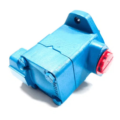
Before you can diagnose a section, you have to know which circuit it feeds. That is a machine-drawing exercise, not a pump exercise, and it takes about twenty minutes.
| Circuit duty | Conventional position | Typical section role |
|---|---|---|
| Fast traverse, clamp close, ejector advance: high flow, low pressure | P1 (shaft end) | Largest displacement, lowest pressure duty |
| Core pull, insert, secondary function: medium flow | P2 (middle) | Medium displacement |
| Clamp hold, injection hold, pilot or pilot-operated valve supply: low flow, sustained pressure | P3 (cover end) | Small displacement, held pressure |
Two cautions. The table describes convention, not a rule: confirm the assignment from the model code and the machine drawing, never from position alone. And if the machine’s third circuit needs sustained high pressure rather than pilot flow, a triple may be the wrong architecture, because the cover-end position is the worst place for a high-pressure hold.
Which section has failed: six checks in order
The pump runs, three circuits exist, and one of them is weak. The question is whether the fault is in a cartridge, a support plate, the relief valve, or the circuit downstream. Run these in order and stop when one produces a result.
1. Map the symptom to a port. Write down which machine function is slow or weak, then trace it to an outlet. Without this step, every later measurement is ambiguous, because “the pump is down on pressure” is not a statement about any particular section.
2. Measure at the weak port, against that port’s rating. Not the pump’s headline rating, and not P1 because it is easiest to reach. Compare the reading to the continuous figure for that port on that frame. A P3 reading of 150 bar is a fault against a 160 bar continuous rating; the same 150 bar at P1 would be normal.
3. Watch the reading as the oil warms. A section that holds pressure cold and fades over twenty minutes has a clearance problem: typically vane tips, cam ring wear, or a support plate that is not seating. A section that is low from cold has a different cause: a stuck or broken vane, a damaged seal, or a relief that is passing.
4. Isolate the section from its circuit. Cap the outlet at the pump, fit a test gauge and a flow meter, and load the section against its own relief. If the section now holds pressure and flow, the pump is sound, and the fault is downstream: a cylinder packing, a directional valve spool, a leaking hose, or a relief set too low. If it still fails, the fault is inside the pump.
5. Check for cross-port leakage between sections. With one outlet loaded and the others at low pressure, watch for flow or pressure appearing where it should not. A section reading low while an adjacent outlet reads high, or a circuit that creeps when it should hold, is the signature. The mechanism is usually mechanical: a cover screw left loose, a support plate not seated square, or a distribution plate lifted in assembly. All three let the high-pressure chamber communicate with the low-pressure one.
6. Inspect per section on teardown. Once the pump is out, inspect each cartridge separately and record what you find against its section number. Look for vane tip wear, cam ring scuffing on the pressure side, support-plate flatness, washboarding on the inlet side, and fretting at the cartridge seat. One worn cartridge beside two clean ones is a normal pattern; three equally worn cartridges point to a system problem (contamination, heat, or a suction restriction), and a new pump will not fix it.
Failures that mimic a bad cartridge
Three multi-section faults are routinely misdiagnosed as cartridge wear, and all three are much cheaper to fix than a rebuild.
- A loose or unevenly torqued cover. The cover clamps the whole stack. If it is not seating evenly, high- and low-pressure chambers can interconnect, and the symptom looks exactly like a worn section in the middle of the stack.
- A distribution plate that has not seated. The plate has to sit square and fully home. A plate caught on an edge produces internal leakage concentrated at one section, often the one nearest the cover.
- Casting porosity in the housing. Rare, but it appears as two pressures “in series”: a section that cannot reach its rating no matter what you replace. If a rebuilt pump with new cartridges in every position still fails the same way, suspect the housing before you suspect the kits.
Pump already off the machine? Send the full three-section model code, the per-port test readings and a photo of each cartridge. We will tell you which section the numbers point to before you commit to parts.
For single-pump symptoms that are not section-specific (noise, cavitation, aeration, shaft seal leakage), use the vane pump troubleshooting sequence instead. It covers the pump as a whole; this page covers the separation between sections.
Three cartridges, three kits
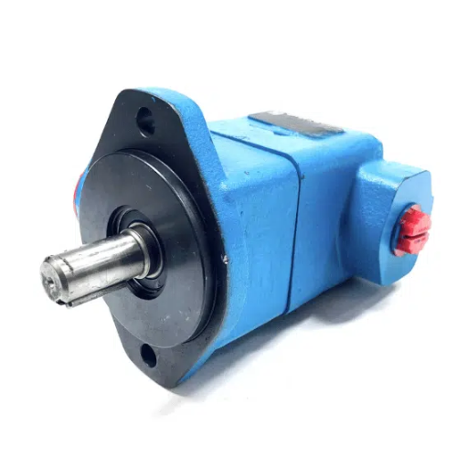
A triple pump needs three kits, and buying the wrong one is easy because the model code does not label them. It orders them.
Each displacement code corresponds to a position in the stack, shaft end first. The Denison convention reads T6EDC-072-042-020E is the shaft-end cartridge, D the middle, C the cover end, each letter carrying its own displacement code. Vickers combines families: 2520VQSV10 is a 25VQ and a 20VQ with a V10 section at the front. Tokimec lists three displacements in order inside a longer string, such as SQP432-60-38-15.
| Position in code | Section | Kit maps to |
|---|---|---|
| First displacement / first letter | Shaft end (P1) | Shaft-end cartridge kit |
| Second | Middle (P2) | Middle cartridge kit |
| Third | Cover end (P3) | Cover-end cartridge kit |
Read the code position against both the nameplate and the section itself; do not infer it from displacement size. Two sections can carry the same displacement code, and a pump rebuilt with the right kits in the wrong order will run, leak internally, and test low in a way that looks like a manufacturing fault.
A kit typically contains the rotor, vanes, cam ring, support plates, and the seals internal to that cartridge. The shaft seal is usually a separate item, which matters on a pump leaking at the drive end, and that leak is not a cartridge symptom.
Kit numbering follows the OEM and carries the fluid and rotation information. A Tokimec C-KIT-F11-SQP4-50-18 names the fluid class in the prefix, and an L suffix denotes left-hand rotation. Vickers triple kits are documented in the M-249x-S parts lists for the corresponding configuration. For what a kit contains, the replacement sequence, and the rebuild-versus-replace thresholds, see vane pump cartridge kit; for reading the full code, see decoding a vane pump model code.
When one kit is not enough. Replace the failed section only when the other two pass a flow test, and the housing passes inspection. Replace the whole unit when the housing shows deformation or porosity, when the shaft is worn at a bearing journal, or when all three sections are tired: three rebuilds approach the cost of a replacement assembly, and the housing has absorbed the same duty as the cartridges.
Before you test or open the circuit
Hydraulic systems store energy. Isolate the pump, lock out the drive, and relieve stored pressure at every accumulator and at every circuit before loosening a fitting. Oil at system pressure can inject through the skin, and a circuit that “looks dead” may hold pressure behind a check valve for hours.
Two more notes on method. The isolation sequence above is systematic engineering reasoning, not a published service procedure; confirm the specifics for your model against the OEM service manual before relying on it for a warranty or safety decision. And take the test readings with a calibrated gauge and a flow meter, since a pressure reading alone cannot distinguish a worn section from a relief that is passing.
About the ratings on this page
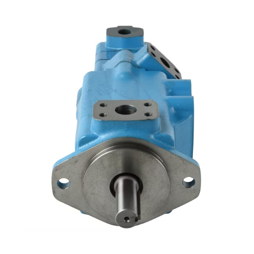
The per-port bands come from distributor specification tables for the Parker/Denison T6, T67 and T7 family and show the pattern across it; the manufacturer’s documents remain the authority for a specific model, frame and seal class. The Hydraulic Institute publishes guidance on pressure ratings and duty classification, the Danfoss PowerSource V series pages cover the related Vickers line, and this Fluid Power World overview explains why vane pumps have a pressure ceiling.
Frequently asked questions
Why is port 3 rated lower than port 1 on a triple vane pump?
Because it sits at the far end of the load path. The cover-end housing absorbs the combined heat and deflection of all three sections with none of the shaft-end stiffness, and the cover-end cartridge is normally the smallest in the stack, so each vane carries more load per unit of flow. The published P3 bands sit inside a narrower and generally lower window than P1.
How do I know which section of my triple vane pump has failed?
Map the weak function to its outlet, then measure that port against its own continuous rating, not the pump’s headline figure. If the reading is low, cap the outlet and test the section alone: one that holds pressure in isolation points to the circuit, one that does not points to the cartridge. Warm-up behaviour and cross-port leakage then separate a worn cartridge from a housing fault.
Can all three sections run at the same time?
Yes, and they usually do. The constraint is mechanical, not hydraulic: the shaft carries the sum of the three input torques, so simultaneous demand from all three sets the drive sizing. Size the motor and coupling for the worst simultaneous case, not the largest single section.
How many cartridge kits does a triple vane pump need?
One per section, so three. The position of each displacement code in the model string tells you which kit belongs where; the first set is the shaft end. Replace only the failed section when the other two pass a flow test, and the housing is sound.
Can I replace one section without removing the whole pump?
On most industrial vane families, the cartridges are independent of the shaft, so a section can be serviced in place or on the bench, depending on access and the OEM procedure. A single worn cartridge is a straightforward job; a housing or shaft fault means the pump comes out.
Conclusion
A triple vane pump is three pumps sharing a shaft and a housing, and it should be specified, tested, and rebuilt that way. Check the per-port rating before you buy, measure each outlet against its own rating before you diagnose, and map the kit to the section from the code before you order.
If you are specifying a replacement or working through a fault on a three-section pump, send us the nameplate photo, the full model code, and your per-port test readings. We will confirm the section ratings for your exact frame and tell you which kit the numbers point to. Contact our engineering team with the details.