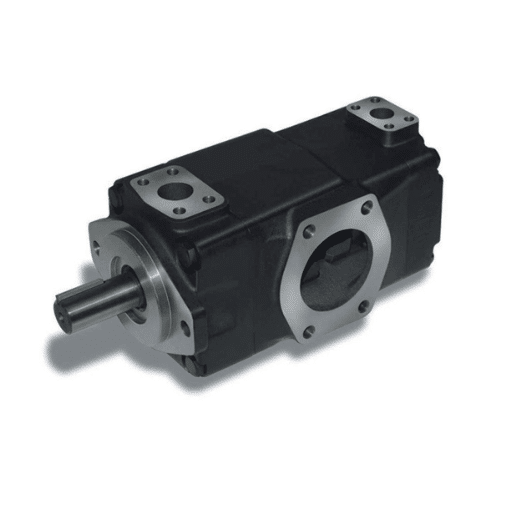
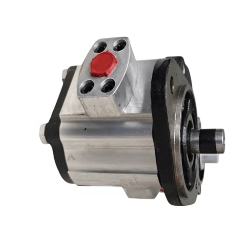
Put a hand on a running vane pump, and you feel almost nothing: no surge, no hammer, barely a hum. That smoothness is not cosmetic. It comes out of the geometry inside the housing, where a ring, a rotor, and a set of sliding blades turn rotation into flow with as little as 2% ripple.
Ask most people, “How does a vane pump work?” and you get one sentence: “an eccentric rotor with sliding vanes.” True, and nearly useless. It does not explain why the pump cannot run slowly, why it needs cleaner oil than a gear pump, or why it re-seals itself as it wears.
This article answers that question properly: how does a hydraulic vane pump work, part by part. That means the mechanism, the geometry that fixes displacement, the force balance that keeps the vanes sealed, and the limits that follow from both. For the wider family picture, see our complete guide to hydraulic vane pumps.
Vane Pump Working Principle: A Rotary Positive-Displacement Machine

A vane pump is a rotary positive-displacement machine. It traps a fixed volume of fluid and pushes that volume through, rather than throwing fluid outward with an impeller the way a centrifugal pump does. That distinction governs the whole machine: a positive-displacement pump delivers close to the same volume per revolution no matter what resistance it meets downstream. The pump creates flow, and the system’s resistance converts that flow into pressure.
Within the fluid power family, the vane design sits in the middle, quieter and smoother than a gear pump of similar displacement but cheaper and more contamination-tolerant than a piston pump. In return, it asks for clean oil and a speed floor. For a broader comparison, see our types of hydraulic pumps explained guide.
Scope note. This article covers the hydraulic vane pump. A rotary vane vacuum pump shares the sliding-vane geometry but runs below atmospheric pressure, seals against air rather than oil, and uses very different clearances. The mechanics here do not transfer to it.
In one sentence: a vane pump traps fluid between sliding vanes in a rotor that sits off-centre inside a cam ring. As the rotor turns, the gap between rotor and ring opens to draw fluid in, then closes to push it out.
Sizing a circuit around a specific flow and pressure? Request a technical specification sheet, and we will confirm displacement, pressure rating, and mounting.
Vane Pump Components and How They Fit Together
Rotor and vane slots. The rotating hub, splined to the drive shaft, with one radial slot per vane. A slot worn out of parallelism lets the vane tilt and lose its seal.
Vanes. Flat hardened steel plates that slide in the slots. Their tips ride against the cam ring and their edges seal against the side plates. Vane thickness drives flow ripple.
Cam ring (also called the stator ring). The hardened ring the vane tips run against; its shape and position relative to the rotor set displacement.
Port plate. The stationary face carrying the kidney-shaped inlet and outlet openings.
Side plates. They close the rotor faces and form the axial sealing surface; at least one is often a floating, pressure-compensated plate.
Drive shaft and bearings. They transmit torque and, in single-acting designs, absorb the radial load.
| Component | Function | Typical wear mode |
|---|---|---|
| Rotor and vane slots | Carries vanes; defines chamber volume | Slot wear allows vane tilt and leakage |
| Vanes | Extend to seal against ring and side plates | Tip wear, chipping, edge rounding |
| Cam ring | Track for the vane tips; sets displacement | Washboarding; bore grows past limit |
| Port plate | Times the inlet and outlet windows | Erosion and cross-port leakage |
| Side plates | Close the rotor faces | Face scoring; loss of clamping force |
| Shaft and bearings | Transmit torque; absorb radial load | Bearing spalling from side load |
How Does a Vane Pump Work? The Suction, Transport, and Discharge Cycle
Short answer. Fluid is trapped in the space between two vanes. Because the rotor is off-centre inside the ring, that space grows while it passes the inlet and shrinks while it passes the outlet. At least one vane must always separate the inlet from the outlet.
Step 1: Suction. On the wide side of the ring, the pocket between two adjacent vanes grows, and its internal pressure falls, so atmospheric pressure on the oil surface pushes fluid through the inlet port to fill it. This is why the pump is called self-priming.
Step 2: Transport. The vanes carry the trapped fluid around the ring. Vane tips contact the cam ring while the vanes and side plates close the remaining boundaries, so fluid cannot leak back past the inlet.
Step 3: Discharge. On the narrow side, the gap closes, and the pocket collapses, so the fluid has nowhere to go but out through the discharge port. Chamber volume falls to nearly zero at the narrowest point, which is why almost everything drawn in is expelled.
What moves the fluid is a sealed volume that changes size, not a pressure-generating device.
Self-priming is not the same as dry-run safe. The vanes, tips, and side plates rely on a lubricating film, and running dry destroys it. Tomas Berg found this at a Swedish machine-tool plant in 2023, when a 25 cm³/rev pump ran for ninety seconds during a commissioning test with the inlet valve still shut. The cam ring and vane tips scored, and the pump lost roughly a third of its rated flow.
Vane Pump Eccentricity and the Displacement Formula

Eccentricity is the distance between the rotor’s axis and the cam ring’s axis. Move the rotor off-centre, and it carves the crescent-shaped space whose volume changes as the rotor turns. Set the offset to zero, and the pockets hold a constant volume, so the pump moves nothing. Zero eccentricity means zero flow.
That fact explains how a vane pump is sized, and it is also why this family can be built as a variable-displacement pump. Because the cam ring is a separate part, it can pivot inside the housing, changing eccentricity while the pump runs. A compensator spool senses discharge pressure and repositions the ring, so at the pressure setting the output falls and at full deadhead the pump holds pressure while displacing almost nothing.
The Vane Pump Displacement Formula, Derived
The rotor can move off-centre until it touches the ring, so maximum eccentricity is set by the two diameters:
e_max = (D_c − D_R) / 2
Each vane sweeps a radial band of width 2e around the mean circumference between rotor and ring, π(R_c + R_R). Multiply the swept area by rotor width L, then substitute D_c + D_R = 2(D_c − e):
V_D = 2e × π(R_c + R_R) × L = π e (D_c + D_R) L = 2π e (D_c − e) L
This is the same relationship published in our hydraulic pump displacement formula guide, written there as V = 2 × B × e × (D − e) × π. It gives theoretical displacement; the real figure is slightly lower because vane thickness and end clearance reduce the trapped volume.
A worked example: a cartridge with D_c = 70 mm, D_R = 66 mm, and L = 25 mm has a maximum eccentricity of 2 mm and a displacement of 2 × π × 2 × 68 × 25 = 21,363 mm³/rev, or 21.4 cm³/rev. At 1,500 rpm, that is a theoretical 32.0 L/min, and at 92% volumetric efficiency, 29.5 L/min into the circuit.
How Vanes Stay Pressed Against the Cam Ring
A vane only seals if its tip stays against the ring, and the tip only stays there if something pushes it. Three mechanisms share the job.
Centrifugal force. Rotation throws each vane outward. This is the primary extension force, and it scales with the square of shaft speed, which is why the vane pump minimum speed sits between roughly 600 and 900 rpm: below that, centrifugal force alone is too weak to guarantee contact.
Hydraulic pressure under the vane. Drilled passages in the rotor feed discharge pressure to the vane roots. In an intra-vane design, the vane is split into an outer blade and an inner insert (a two-piece vane), and pressure is applied only to the small area between them. The tip is pushed out firmly without being crushed against the ring, which is the trick that lets vane tips survive at 200 bar and above.
Springs and push rods. These provide extension at start-up, before pressure has built and before the shaft has reached speed.
Vane life depends on balancing the discharge pressure acting on the tip against the timed pressure acting on the root: a tip pressed too hard wears quickly, and a tip pressed too lightly lifts off the ring and leaks. When that balance breaks, the failure is dramatic. If inlet pressure falls far enough, the vanes lose ring contact on the inlet side and are driven back onto it on discharge, hammering the tips and the ring. Priya Raghavan, a hydraulic technician at a foundry in Pune, traced this pattern in 2024: a partly blocked suction strainer raised inlet vacuum enough to pit every vane tip within about 40 running hours. The fix is inlet design rather than pump design, which is why OEM service literature advises against an inlet strainer entirely.
The mechanism also re-seals as it wears: as the cam ring bore wears, the gap at the narrow side grows, and the vane simply extends further to close it. An external gear pump cannot do this, because its clearances only open. That contrast is the reason a vane pump holds efficiency over a long service life, and it is worth understanding before you choose between the two.
Why Vane Pump Flow Is Proportional to Speed

For a fixed-displacement vane pump, the volume displaced per revolution does not change, so theoretical flow follows directly:
Q_T = V_D × N
Double the speed, and you double the flow: 32.0 L/min at 1,500 rpm, 64.0 L/min at 3,000 rpm, before losses. It is a common misunderstanding that the pump “creates pressure.” It does not. At a given speed, the pump delivers a nearly fixed flow, and resistance in the circuit decides what pressure appears, which is why every circuit needs a relief valve or a compensator.
Slip, and why clearance cubed matters
Real pumps leak a little fluid back from discharge to inlet, a loss called slip. Leakage through a narrow gap scales with the cube of that gap: double a clearance and the leak grows roughly eightfold. That is why vane pumps specify finer filtration than gear pumps. A 10 µm particle a gear pump would tolerate can hold a vane clear of its seal or damage a side plate, and the resulting increase in clearance is punished cubically.
The pressure-compensated side plate
Vane pumps answer slip with a floating side plate. Discharge pressure is routed behind the plate, so rising pressure increases the clamping force against the rotor face, closing the axial gap and limiting cross-port leakage. This is one more place where how a vane pump works differs from a gear pump: the vane design holds volumetric efficiency as pressure climbs, where a fixed-clearance design would lose flow.
At rated conditions, expect roughly 92% volumetric efficiency from a single-acting cartridge and above 94% from a double-acting design. Those are typical values at rated pressure and speed, not guarantees: textbook sources quote about 95%, while leakage-based analyses land in the 82% to 92% band.
Speed Limits at Both Ends: Too Slow, and Too Fast
Too slow: vanes float. Below roughly 600 to 900 rpm, centrifugal force cannot hold the vanes against the ring. They bounce, sealing fails intermittently, and the ring surface ripples. The industry name for that damage is washboarding, and once the bore grows past its limit, the fix is a new pump rather than a cartridge. Marta Nowak, a plant engineer at a plastics plant in Kraków, met this in 2025 after a variable-frequency drive was programmed to run a power unit at 500 rpm to save energy. The cam ring was rippled within a few months, and the whole unit had to be replaced.
Too fast: the inlet cannot fill the chamber. As speed rises, the limiting factor shifts to filling. The chamber has less time to fill, inlet pressure falls, and cavitation begins. General-purpose vane pumps run at 1,500 to 2,000 rpm, with about 3,000 rpm as a practical ceiling for single-acting designs unless the inlet is specifically engineered. Small double-acting units, whose geometry helps the inlet, run to 8,000 or 10,000 rpm. Thick, cold oil fills the chamber slowly, so a cold start at low speed is the worst combination for vane extension.
Single-Acting vs Double-Acting: How the Mechanism Changes
In a single-acting (unbalanced) pump, the cam ring is a circle, and the rotor sits off-centre inside it, so the pump draws in and discharges once per revolution. Pressure acts on one side of the rotor only, so the shaft and bearings carry a steady radial load. Because the ring can pivot, this is the layout that can be made variable displacement.
In a double-acting (balanced) pump, the ring is slightly elliptical, and the rotor sits at its centre. Two inlet and two discharge ports sit opposite each other, so the pump delivers two pulses per revolution and the pressure forces on opposite sides of the rotor cancel. Radial shaft load is nearly zero, which allows higher pressure and longer bearing life, but eccentricity cannot be varied, so these pumps are fixed displacement only.
| Feature | Single-acting | Double-acting |
|---|---|---|
| Cam ring shape | Circular, rotor offset | Elliptical, rotor centred |
| Cycles per revolution | One | Two |
| Radial load on shaft | High, one direction | Near zero, self-cancelling |
| Displacement | Can be made variable | Fixed only |
| Flow pulsation | Roughly 5% to 10% | Typically under 2% |
Why the vane count sets pulsation
Each vane crossing the discharge port adds one pulse, so vane passing frequency equals the number of vanes multiplied by shaft rpm. A 10-vane pump at 1,500 rpm pulses at 250 Hz, and a 12-vane pump at 300 Hz. That vane passing frequency is what shows up in pressure-ripple measurements and tonal noise, which makes a noise complaint diagnosable. Vane pump flow ripple amplitude is driven mainly by vane thickness, which is why geometry studies of theoretical flow ripple in balanced vane pumps focus on vane and ring profile. Balanced designs hold ripple under 2%.
One terminology warning. “Double-acting” describes the balanced geometry of a single cartridge; “double vane” or tandem describes two cartridges on one shaft. They are different things.
What the Mechanism Demands in Practice

| Parameter | Practical target |
|---|---|
| Minimum speed | 600-900 rpm |
| Typical operating speed | 1,500-2,000 rpm |
| Continuous pressure | 70-210 bar, with heavy-duty designs above this |
| Filtration | 10-25 µm absolute |
| Cleanliness | ISO 4406 18/15 to 140 bar; 17/14 for 140-210 bar |
| Fluid temperature | Below 60 °C |
| Inlet line velocity | At or below 1.9 m/s |
| Coupling alignment | Within 0.05 mm |
Every row traces back to the mechanism. Speed has a floor because of vane extension and a ceiling because of inlet filling. Filtration sits finer than the roughly 25 µm band typical of gear pumps, because leakage scales with the cube of clearance. Inlet design carries no strainer by preference; where one is unavoidable, keep the mesh coarse and verify the pressure drop.
Working through a replacement or a new build? Contact our engineering team for a customized hydraulic system recommendation, including cartridge selection and an OEM quotation against your drawings.
Frequently Asked Questions
How does a vane pump work in simple terms?
A rotor with sliding vanes turns off-centre inside a ring. The space between two vanes grows as it passes the inlet, drawing fluid in, then shrinks as it passes the outlet, pushing fluid out.
What is the working principle of a hydraulic vane pump?
A hydraulic vane pump is a rotary positive-displacement machine. A sealed chamber of changing volume carries fluid from inlet to outlet, so the pump produces a fixed volume per revolution rather than generating pressure directly.
What is eccentricity in a vane pump?
It is the offset between the rotor axis and the cam ring axis. It creates the crescent-shaped chamber whose volume changes as the rotor turns, and it sets displacement.
What happens if eccentricity is zero?
The rotor runs concentric with the ring, chamber volume stays constant, and the pump displaces nothing. A pressure-compensated variable pump reaches exactly this state at deadhead.
Why can’t a vane pump run at very low speed?
Below roughly 600 to 900 rpm, centrifugal force is too weak to hold the vanes against the ring. They bounce, sealing fails intermittently, and the cam ring can be damaged permanently.
Is a rotary vane vacuum pump the same as a hydraulic vane pump?
No. A vacuum pump runs below atmospheric pressure and seals against air at very different clearances. A hydraulic vane pump runs at 70 to 210 bar and seals with an oil film.
How Does a Vane Pump Work: Key Takeaways
A vane pump converts rotation into flow by sweeping sealed chambers of changing volume between an eccentric cam ring and a slotted rotor. Eccentricity sets the displacement, centrifugal and hydraulic forces keep the vanes sealed, and the sliding-vane geometry lets the pump re-seal itself as it wears. The derivation is short: V_D = 2π e (D_c − e) L, and it states plainly that zero eccentricity means zero flow.
Once you understand how a vane pump works, the family’s rules stop looking arbitrary. The 600 to 900 rpm floor is the vane extension limit. The fine filtration specification is the cube of clearance. The inlet guidance exists because a starved vane hammers the ring. And the roughly 210 bar continuous ceiling is where the mechanism’s forces make the piston family the better answer.
Ready to specify? Request a technical specification sheet or send us the drawings and duty cycle for a factory-direct OEM quotation. We supply gear, vane, and piston families, and we will tell you plainly which one your application actually needs.