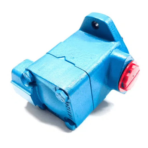
Triple vane pump selection comes down to three decisions in a fixed order: how many circuits the machine needs, which position on the pump each circuit occupies, and which displacement code fits that position’s own list. Get the order right, and the code follows. Get it wrong, and you can specify a build that reads correctly on paper and still fails on the machine.
Most advice starts at the pump. This page starts at the cycle.
Key Takeaways
- Each position on a triple draws from its own displacement list, so the same number means a different displacement at P1, P2 and P3.
- Round up on delivered flow at the circuit’s pressure, not on displacement alone. A code that looks big enough at 0 bar can be short at 100 bar.
- Triple vane pump pressure ratings follow the frame letters in model-code order, not the position numbers. “P3 is the weak port” is false on half the builds in the catalogue.
- The cover-end section has a floor as well as a ceiling: too small, and internal leakage eats more than half its output at the top of its range.
- Shaft torque is a sum check across all three sections, never a per-section check.
What does triple vane pump selection actually mean?
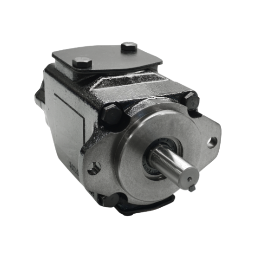
Triple vane pump selection is the process of allocating a machine’s three hydraulic circuits to the three cartridge positions of one pump body, then converting each circuit’s flow and pressure into a catalogue displacement code. Each position accepts a different list of codes and carries a different pressure ceiling.
| Decision | What you are deciding | What constrains it |
|---|---|---|
| 1. How many sections | Whether the circuits group into three flow and pressure bands | The number of functions that must run independently |
| 2. Which position | Shaft end (P1), middle (P2) or cover end (P3) | Each position’s displacement list and its frame’s pressure cap |
| 3. Which code | The displacement value inside that position’s list | Delivered flow at the circuit’s pressure, rounded up |
The order matters, because position constrains the code and not the reverse. You cannot pick a number you like and then find a position for it, because the number may not exist in the list that position accepts. On a T7DCB, the three lists are B14–050, 003–031 and B02–B15: three ranges, three starting sizes.
If you already have the three flows and three pressures, send us a quote, and the allocation can be checked against the per-port limits before you order.
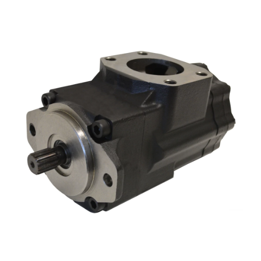
A triple vane pump is one body with three cartridge sections on a single shaft, driven by one motor. The sections serve a high and low circuit, plus one separate function. In catalogue terms, a three-section vane pump is exactly that: three displacement codes on one model string, one per position. Parker describes the combination as allowing “low flow at high pressure (300 bar max.) and high flow at lower pressure”, with fast pressure-cycle change and repeatable flow (catalogue HY29-0001/UK, a distributor-hosted copy; ask Parker Hannifin for the current revision).
Scope note: the general duty-to-position convention is on the triple vane pump guide, the ratio theory is on the guide to how double and triple vane pumps are configured, and the single-pump formulas are on vane pump sizing. This page is the arithmetic that connects them.
Start from the machine cycle, not the pump
Five steps, in this order. Skipping one is how a build ends up matching a code and not a machine.
- List every hydraulic function with its flow and pressure. Not the pump’s rating, the machine’s requirement.
- Group the functions into flow and pressure bands. Functions at similar flow and pressure can share a section, and this grouping decides how many sections you need.
- Assign each band to a position by duty. The largest flow goes where the list reaches that displacement; the highest pressure goes where the frame carries that ceiling.
- Convert each band’s flow to displacement at the drive speed. Vane pump displacement in millilitres per revolution equals flow in litres per minute times 1,000, divided by speed in revolutions per minute. At 1,500 rpm, 90 L/min needs 60.0 ml/rev.
- Land each displacement on that position’s own code list, rounding up. Then check delivered flow at the circuit’s actual pressure, and re-check whether you rounded up far enough.
The second half of step 5 is the half most people skip. A pump’s flow column is not a single number: the catalogue prints flow at 0 bar, at 140 bar and at the port’s ceiling, because delivered flow falls as pressure rises.
Field note: when a circuit needs 25 L/min at 100 bar, do not accept a code whose 0 bar column reads 25.8. Interpolate the row at 100 bar and compare there. Internal leakage rises with pressure, and the gap is often 10% to 15%.
Worked allocation 1: a 400 t injection moulding machine
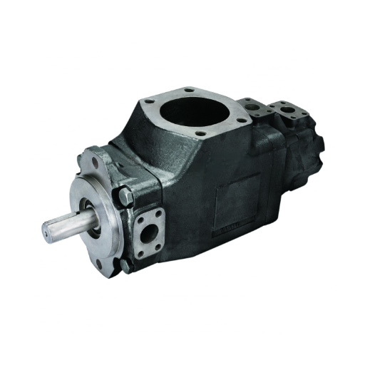
The duties below are example duties for a machine of this class, not a manufacturer’s specification. The arithmetic and the catalogue codes are the point.
| Circuit | Flow required | Pressure | Displacement needed |
|---|---|---|---|
| Fast clamp close | 90 L/min | 70 bar | 60.0 ml/rev |
| Ejector and core pull | 25 L/min | 100 bar | 16.7 ml/rev |
| Clamp and injection hold | 6 L/min | 160 bar | 4.0 ml/rev |
Landing these at a 1,500 rpm drive on a T7DCB stack gives B20 for the clamp circuit (66.0 ml/rev), 005 for the ejector circuit (17.2 ml/rev) and B02 for the hold circuit (5.8 ml/rev). On displacement alone, that first pass is correct.
The second half of step 5 changes one of them. Code 005’s 0 bar column delivers 25.8 L/min, a comfortable match for a 25 L/min circuit. At 140 bar, the same row reads 20.8 L/min, so the interpolated delivery at 100 bar is 22.2 L/min, which is 2.8 L/min short. Code 006, at 21.3 ml/rev, delivers 31.9 at 0 bar and 26.9 at 140 bar, or about 28.3 L/min at 100 bar.
| Position | Code | Displacement | Delivered at circuit pressure | Port ceiling |
|---|---|---|---|---|
| P1 (shaft end) | B20 | 66.0 ml/rev | 95.7 L/min at 70 bar (needs 90) | 250 bar |
| P2 (middle) | 006 | 21.3 ml/rev | 28.3 L/min at 100 bar (needs 25) | 275 bar |
| P3 (cover end) | B02 | 5.8 ml/rev | 6.8 L/min at 160 bar (needs 6) | 300 bar |
Two things in that table are worth pausing on. The first is why the large circuit had to go to P1, and it is not a preference: the cover position on this stack accepts B02 through B15, and B15 is 50.0 ml/rev, which is 75 L/min at 1,500 rpm. A 90 L/min circuit cannot be a cover-end section on this build at any pressure.
The second is the ratings. The triple vane pump pressure rating runs 250, 275, and 300 bar in position order, so the cover-end section is the strongest port on this build, not the weakest. That is not a quirk; it follows from the frame letters.
On the drive side, hydraulic power is the sum of flow times pressure over 600 per section: 11.17 + 4.72 + 1.81 = 17.70 kW. Shaft power is higher because no pump is lossless, and the catalogue prints flow and input power in the same row, so its implied efficiency can be read off directly: on the B20 section at 140 bar, 21.56 kW hydraulic against 24.30 kW input, or 88.7%. Dividing 17.70 by 0.887 gives about 20.0 kW at the shaft.
Then the sum check. Parker rates shafts by the sum of displacement times pressure across all three sections: 66.0 × 70 + 21.3 × 100 + 5.8 × 160, or 4,620 + 2,130 + 928, for 7,678. The T7DCB’s shaft 1 limit is 43,240 on the same scale, so this allocation uses about 17.8% of its shaft capacity. It is a comfortable build because the largest section is loaded at the lowest pressure.
If you need the rest of the model string, how to read the full model code covers the mounting, shaft, and port fields that follow the three displacement codes. If you already have a duty cycle, the three flows, three pressures, and drive speed are all a supplier needs to start.
Worked allocation 2: a die-casting cell, where the cycle is sequential
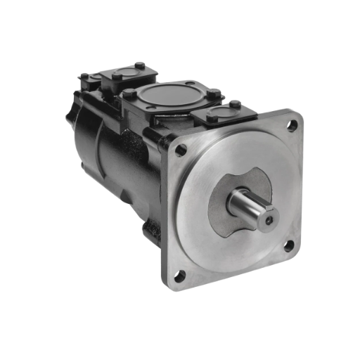
The second machine has a different shape. Its three functions never run together: fast close, then ejection, then intensification. This is the case where a simultaneous sum overstates the duty. Our own page on the vane pump for die-casting machines covers the machine-side duties; this allocation is the pump-side arithmetic on top of them.
| Circuit | Flow required | Pressure | Displacement needed |
|---|---|---|---|
| Fast close | 200 L/min | 80 bar | 133.3 ml/rev |
| Ejector | 50 L/min | 100 bar | 33.3 ml/rev |
| Intensification | 20 L/min | 160 bar | 13.3 ml/rev |
On a T67EDC stack: 045 for the fast close (142.4 ml/rev), B14 for the ejector (44.0 ml/rev), and 005 for intensification (17.2 ml/rev).
| Position | Code | Displacement | Delivered at circuit pressure | Port ceiling |
|---|---|---|---|---|
| P1 (shaft end) | 045 | 142.4 ml/rev | 207.9 L/min at 80 bar (needs 200) | 240 bar |
| P2 (middle) | B14 | 44.0 ml/rev | 61.3 L/min at 100 bar (needs 50) | 250 bar |
| P3 (cover end) | 005 | 17.2 ml/rev | 20.1 L/min at 160 bar (needs 20) | 275 bar |
Read the margins, because they teach the opposite lesson. The cover-end section has a 0.5% margin, tight enough to matter and honest enough to state. The middle section has 22.6%, and the reason is coarseness: the D list has no code between 44.0 and 55.0 ml/rev, so the next step down is not available. At the small end of a list, coarse steps cost you flow margin.
The ceilings on this build are 240, 250, and 275 bar. The middle port is the weakest, not the cover end. The E/D/C stack inverts the habit that the D/C/B stack reinforced.
On the drive side: 27.72 + 10.22 + 5.36 = 43.30 kW hydraulic, and the 045 row implies 89.8% overall efficiency at 140 bar, so the shaft estimate is about 48.2 kW. The torque sum at duty is 11,392 + 4,400 + 2,752 = 18,544 against the T67EDC shaft 1 limit of 114,600, or 16.2%. Summing at each port’s tabulated ceiling instead gives 34,176 + 11,000 + 4,730 = 49,906, or 43.5%. The gap between those two figures is the gap between what the pump does and what it could do with every section held at its rating at once.
That is where the sequential cycle matters. Parker states that T7 and T67 units “may be operated intermittently at pressures higher than the recommended continuous rating when the time-weighted average of pressure is less than or equal to the continuous duty pressure rating”, within stated speed, fluid, viscosity, and contamination limits, with a caution for cycles longer than 15 minutes. Its worst case is a double pump, T7B with B10, on 4 minutes at 320 bar, 1 minute at 35 bar and 5 minutes at 160 bar: (4 × 320 + 1 × 35 + 5 × 160) ÷ 10 = 211.5 bar against 290 bar continuous.
The same arithmetic works port by port. Take P1 of this build on a 12-second cycle: 1.2 seconds at 80 bar during fast close, then 10.8 seconds at about 10 bar while the pump circulates unloaded. (1.2 × 80 + 10.8 × 10) ÷ 12 = 17.0 bar, against a 240 bar continuous rating. Parker states the rule for a pump rather than for each port, so treat the per-port version as the same arithmetic carried one level down.
To learn more information, please read our article on Vickers triple vane pumps.
The cover-end section has a lower bound as well as an upper bound
Oversizing is the mistake people expect on a triple vane pump. Undersizing is the one that hides.
Take the die-casting build and swap the cover code from 005 to 028, which is 88.8 ml/rev. At 160 bar it delivers 127.8 L/min where the circuit needs 20.1. The difference, 107.7 L/min, has nowhere to go but across the relief valve, and 107.7 × 160 ÷ 600 = 28.7 kW of continuous heat.
That is 66% of the pump’s entire useful hydraulic power, generated as heat at the relief. The oversized section also runs at roughly half the efficiency of the matched one: the catalogue’s columns imply 50.0% on a small cover section held at its top pressure, against 88.7% on the B20 section at 140 bar.
That 028 code is legal on this build and not on the first one. The T67EDC’s cover position accepts the C list, 003 through 031, so 028 fits. The T7DCB’s cover position accepts the B list, B02 through B15, which stops at 50.0 ml/rev. Moving a code between models to make an illustration work is how bad build sheets get written.
Now the other direction, which the catalogue documents and no selection guide repeats. On the T67EDC’s cover position, size 003 is flagged:
“We do not recommand to use the size 003 in P3 at 275 bar & 1500 RPM as the internal leakage is over 50% of theoretical flow.”
The spelling is the catalogue’s. The arithmetic is blunt: 003 displaces 10.8 ml/rev, so at 1,500 rpm its theoretical flow is 16.2 L/min. If more than half leaks internally at 275 bar, more than 8.1 L/min never reaches the circuit. On a 20 L/min duty, that is fatal, and it fails quietly, because the pump runs, sounds normal, and heats the oil.
The port name in that note is not fixed, and this matters when you quote it. The note appears on eight pages, and the port it names is always the port whose list carries the 003 code: P1 on the T67CB, P2 on the T7DCB and T67DC, “P2 and P3” on the T7DCC, P3 on the T67EDC and T7EEC.
Between those bounds there is a practical window rather than a rule: a cover section sized to the circuit’s flow, with enough headroom that delivered flow at the circuit’s pressure still clears the requirement, and not so much that the relief is doing the metering. When the third circuit needs only pilot flow, a double pump plus a separate small unit is often the better answer, and the Denison triple vane pump comparison shows where that trade lands across the family.
Three checks that catch a bad allocation before you order
Run these in order, because a failure at the first two changes the build and a failure at the third changes the machine.
| Check | What it protects | The figure you compare | Where it comes from |
|---|---|---|---|
| Per-port pressure | The cartridge, and the pump body at that position | Circuit pressure against that port’s ceiling, using the multi-unit cap | Frame caps and the model’s own table |
| Combined shaft torque | The shaft, coupling and drive | Sum of displacement × pressure across all three sections, against a shaft limit | Shaft torque table, or T = (9554 ÷ N) × L |
| Minimum speed | Vane extension and volumetric efficiency | Lowest speed the machine runs, against the minimum for that section | Catalogue speed range |
Check 1, per-port pressure. Multiple-pump builds use the lower multi-unit frame cap: in the Parker T7/T67 series the single-pump caps are A 300, B 320, C 275, D 280 and E 240 bar, but the B frame drops to 300 and the D frame to 250 for multiple pumps. Each model’s performance table already applies those figures, so read the port’s own column rather than derating by hand.
Across the eight industrial triples in that catalogue, each port’s ceiling equals that frame’s multi-pump cap, read in the order the frames appear in the model code:
| Model | Frames | P1 | P2 | P3 |
|---|---|---|---|---|
| T7DBB | D B B | 250 | 300 | 300 |
| T7DCB | D C B | 250 | 275 | 300 |
| T7DCC | D C C | 250 | 275 | 275 |
| T7DDB | D D B | 250 | 250 | 300 |
| T67DDCS | D D C | 250 | 250 | 275 |
| T7EDB | E D B | 240 | 250 | 300 |
| T67EDC | E D C | 240 | 250 | 275 |
| T7EEC | E E C | 240 | 240 | 275 |
The P1 column is 240 bar on all three E-frame models, and the P3 column is 300 bar on four builds. The hierarchy belongs to the frame letters, and the position number tells you nothing on its own. The catalogue does not state this as a rule; it is what the eight tables agree on.
Check 2, combined shaft torque. Two Original Equipment Manufacturer (OEM) methods, same purpose. Parker compares the displacement-times-pressure sum against a limit printed per shaft type: 43,240 for shaft 1 on a T7DCB, 114,600 on a T67EDC. The Eaton Vickers Design Guide 353 expresses the same idea as a torque sum with a hard limit, and states that you should “never assume pumps in a double, triple or thru-drive pump assembly can be simultaneously loaded to rated pressure”. Its triple shaft ratings run 344 N·m, 791 N·m and 1,017 N·m by drive shaft designation.
Tokyo Keiki uses the second form, T = (9554 ÷ N) × L, with N in min⁻¹ and L the shaft input in kW. Its SQP catalogue works a case: SQP432-60-38-14 at 1,200 min⁻¹, sections drawing 57.1, 36.2 and 18.4 kW for 111.7 kW, so T = 9554 × 111.7 ÷ 1,200 = 889.3 N·m against a 950 N·m limit. That build passes with 6% to spare.
Check 3, minimum speed. Vane sections need enough speed to throw the vanes out and seal. Eaton puts the minimum recommended starting speed at “generally 600 r/min” under stated fluid conditions.
Denison’s industrial range quotes 600 rpm minimum and 2,200 rpm maximum for multiple-pump builds. Apply the check at the lowest speed the machine actually runs, and confirm fluid viscosity and temperature at that speed, since both move the floor.
For a deep look, see our guide to Tokimec SQP triple vane pumps.
FAQ
How do I know which circuit goes on which section?
Put the largest flow where the list reaches it, and the highest pressure where the frame carries it. The largest flow usually lands at the shaft end, and the highest pressure at the cover end, but the ceiling belongs to the frame letter, so check the table.
Can I use the same displacement code at two positions?
Only if both positions accept it. On a T7DCB, P2 accepts 003 through 031 while P3 accepts B02 through B15, so a code in one list may not exist in the other.
Why does the catalogue’s flow figure not match my calculation?
Because the 0 bar column is theoretical delivery, and delivered flow falls with pressure. On one build here, a code reading 25.8 L/min at 0 bar delivered 22.2 L/min at 100 bar.
Is a bigger cover section always safer?
No. The excess crosses the relief, and the heat is continuous. On the die-casting build, moving the cover code from 005 to 028 turned 20 L/min of useful flow into 28.7 kW of heat, and efficiency falls sharply on small sections at high pressure.
Does a triple vane pump need all three sections loaded at once?
No, and on most machines they are not. That is why the simultaneous torque sum is a ceiling rather than a duty. Check the shaft on the sum, then check each port on its own cycle.
Conclusion
Triple vane pump selection is arithmetic in a fixed order, and the order protects the build.
- Group the machine’s functions by flow and pressure before you look at a pump.
- Convert each band’s flow to displacement, land it on that position’s list, then re-check delivered flow at the circuit’s pressure.
- Read each port’s ceiling from the frame letter, not the position number.
- Sum displacement times pressure across all three sections against the shaft limit.
- Keep the cover section inside a window: big enough for the flow at pressure, small enough that the relief is not generating heat.
Write those five lines down for your own machine and compare the result against a catalogue before you request anything. If you would rather have the allocation reviewed, send the three circuit flows, the three pressures, the drive speed and the duty cycle, and the build can be checked against the per-port limits and the shaft sum at the same time. Ask for a quote on the Denison range with those figures, because pricing follows the exact build rather than the model family.
Safety note: isolating a pump, opening a circuit, or adjusting a relief valve requires the machine to be locked out and the stored pressure vented before any work begins. Confirm the procedure for your machine with a qualified hydraulic technician.