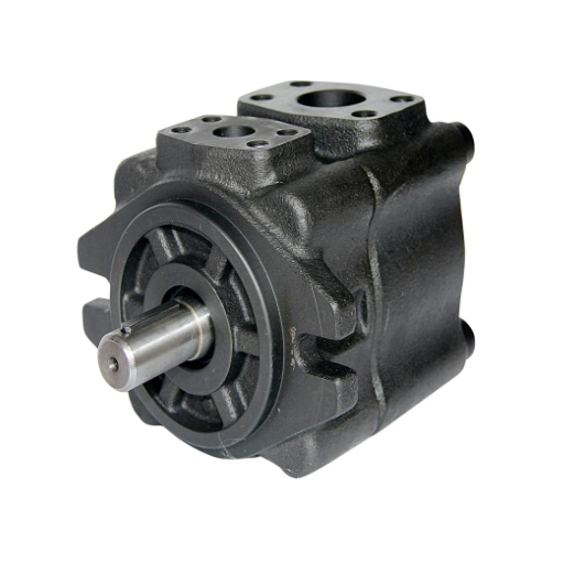
When Elena, a maintenance supervisor at a plastics plant outside Prague, replaced a failed vane pump in November 2024, the replacement cost less than half the original. The listing called it a high-pressure unit. The machine ran at 165 bar. The new pump failed in five months; the original had lasted six years.
The listing was not lying about the pump’s construction. It was lying by omission. It never said what the vane pump pressure limit actually is, where that limit comes from, or what happens when a pump is pushed past it.
That story repeats across industrial hydraulics because almost nobody explains the physics. Catalogues publish a pressure number. Sales pages assert “high pressure” without a rating basis. Engineers inherit the limit without understanding the mechanism behind it, which makes failure analysis, derating, and series selection guesswork.
This article explains the mechanical chain from discharge pressure to cam ring wear, the two independent limits every vane pump carries, the historical baseline of 2,000 psi, the six design responses that moved the ceiling, and why the family is better off accepting a limit than engineering past it. If you need the family fundamentals first, our complete guide to hydraulic vane pumps covers design and type selection. For the series that actually beat this limit, see our high-pressure vane pump guide.
Specifying a circuit near the ceiling? Request a specification-matched quotation with your duty cycle, and we will confirm the rated pressure at your speed and fluid before you commit.
Why Are Vane Pumps Limited in Pressure?
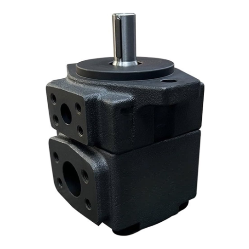
Vane pumps are limited because each vane must slide in its rotor slot while staying pressed against the cam ring. As discharge pressure rises, the extended vane takes excessive side loading, increasing tip contact stress, internal leakage, and wear until the pump can no longer hold its rating. This operational threshold marks where the vane pump pressure limit begins to dictate system design. The primary constraint is vane tip loading: the force concentrated at the vane-cam ring contact point, which is the family-wide pressure limit.
That single mechanism explains the standard industrial ceiling of about 2,000 psi (140 bar) continuous, the engineered exceptions that reach 3,000 to 5,800 psi, and the failure mode that turns a marginal overrun into a dead pump in hours rather than weeks. Everything in this article follows from that sentence.
Fluid Power World’s survey of the category puts the commercial position plainly: standard vane pumps are “often limited to 2,000 psi or less,” and it is “rare to find a vane pump running more than 3,000 psi.” Anything above that is an engineered exception, not a product category.
The Two Jobs of a Vane, and Why Pressure Breaks the Second
Every vane in a vane pump has two simultaneous obligations.
Job one: slide. The vane moves radially in its rotor slot to follow the cam ring profile. On the suction side, the pocket grows; on the discharge side it shrinks. This sliding creates the changing chamber volume that pumps fluid.
Job two: seal. The vane tip must maintain continuous contact with the cam ring across the discharge arc. Without that contact, high-pressure fluid leaks back and the pump loses volumetric efficiency.
At low pressure, both jobs are easy. At high pressure, job two destroys job one: the extended vane is loaded on its side, increasing tip contact stress and wear. Vane extension at start-up depends on centrifugal force — single-acting designs carry a minimum 600–900 rpm speed floor. Our vane pump sizing guide covers the speed rule in full.
Vane Tip Loading: The Primary Pressure Constraint
The force chain is straightforward. Discharge pressure multiplies against the vane’s exposed area, producing a bending moment along the vane’s length. The vane deflects slightly in its slot. All of that force concentrates at the tip, where the contact patch against the cam ring is only a few millimetres wide.
Contact stress at that patch rises steeply with pressure. A NASA-funded study of positive displacement pump wear placed a zero-wear contact-stress criterion near 9,245 kPa (about 1,341 psi) at the tip interface for the materials of its era (NASA contractor report, 1982). Modern hardened vanes and rings move that threshold considerably, but they do not remove the physics.
Above the material’s fatigue limit, the tip wears, the clearance grows, and leakage increases — once clearance passes a critical threshold, the pump’s output collapses. The vane pump pressure limit is defined by this failure threshold and the pV factor that speed and pressure jointly determine.
There is a second factor that multiplies the damage: the pV factor, the product of contact load and sliding velocity. A vane pump rated at 210 bar and 1,200 rpm operates at one pV value. Run the same pump at 2,400 rpm with pressure unchanged and the sliding velocity doubles, pushing the contact well past the safe pV envelope. The pressure rating did not change. The physics did.
Raj, a reliability engineer at a hydraulics workshop in Pune, learned this in 2023. A customer installed a correctly rated 210-bar vane pump on a variable-speed drive and ran it at 2,800 rpm during high-demand cycles. Pressure stayed within the catalogue figure. The vanes failed in eleven weeks. The catalogue rating assumed a fixed speed; the pV factor had never been checked.
Cam Ring Deflection and the Clearance Problem
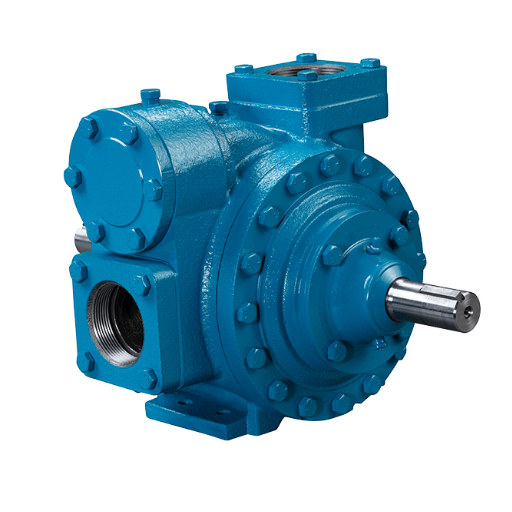
The cam ring, also called the stator ring, is the stationary surface the vane tips run against. In most designs, it is a thin-walled element. Under discharge pressure, it deflects outward locally, opening the tip clearance exactly where pressure is highest. This cam ring deflection is the second physical mechanism that limits vane pump pressure capability, along with vane pump pressure rating variability across frame sizes and displacements.
One experimental study of balanced vane pumps found that roughly 0.2 mm of ring roundness change could cost about 1 L/min of flow (J-STAGE / ISFP, 1999). That sensitivity means wear that starts as surface scuffing becomes a permanent leakage path. A new cartridge restores the vanes; it does not restore a deformed ring.
The side plates create the other leakage boundary. Cheap designs rely on fixed clearances; their volumetric efficiency falls off above roughly 100 bar. Modern designs use pressure-clamped side plates, where discharge pressure forces the cheek plates against the rotor as pressure rises, closing the axial gap automatically. The Vickers patent EP 0582413 documents this hydrostatic balancing approach in detail.
Understanding these physical limits clarifies the vane pump maximum pressure question: no single number suffices. Every rating is frame-, displacement-, and fluid-specific. Together, the compounding clearance problem sets the vane pump pressure limit.
The Compounding Failure Loop
Tip loading and clearances generate internal leakage. Leakage converts pressure energy into heat. Heat raises fluid temperature; above roughly 60 °C, hydraulic oil thins measurably due to viscosity loss. This compounding loop defines the vane pump pressure limit — heat thins the oil, thinner oil leaks faster, and the cycle tightens until volumetric efficiency collapses.
- Vane tip loading and growing clearances create internal leakage.
- Leakage converts pressure energy into heat.
- Heat generation thins the oil above about 60 °C.
- Thinner oil increases leakage through the same clearances.
- More leakage generates more heat, until volumetric efficiency collapses.
- Viscosity loss compounds the loop — thinner oil leaks faster through unchanged clearances.
- Clearance slip accumulates as wear progresses, permanently widening the gap.
This loop is why a vane pump near its ceiling does not fail gradually. It runs acceptably while the cooler keeps up. Once the heat rejection falls behind the loop’s growth, the pump can go from marginal to dead in hours. That is the failure Elena’s plant experienced, and it is the failure mode every high-pressure vane installation must be designed against.
If your pump is already showing symptoms, our vane pump troubleshooting guide covers the diagnostic matrix. The signature that matters most here: noise that worsens as system pressure rises usually points to a restricted inlet or a pump operating at or beyond its limit.
The Second Limit: Radial Side Load on Single-Acting Designs
The radial side load on single-acting designs is a separate constraint from vane tip loading. A second mechanism affects only single-acting (unbalanced) designs.
In a single-acting pump, the discharge arc sits on one side of the rotor and the suction arc on the other. The pressure difference creates a net hydraulic force pushing the rotor sideways. That force travels through the shaft into the bearings. The side load can be estimated as:
F ≈ Δp × D_R × L × k
A mid-size pump with a 70 mm rotor, 30 mm vane width, and 70 bar differential produces a net side load near 10 kN. Early unbalanced designs were limited by bearing capability even at output pressures as low as 600 to 700 psi (US Patent 2885960). The bearing became the design constraint before the pumping elements did.
The classic single-acting ceiling reflects this: simple builds at 60 to 70 bar, standard industrial forms around 175 bar, and modern pressure-compensated designs reaching approximately 250 bar. Our single-acting vane pump guide derives the full analysis.
Double-acting (balanced) designs cancel this radial force by placing two discharge zones diametrically opposite each other. Net shaft load approaches zero under symmetric loading, which is why the balanced architecture is the high-pressure path. Our double-acting vane pump guide owns the “69 bar, 175 bar, or 320 bar?” question in full.
The honest qualification: balancing the rotor does not balance the vane. Tip loading is a separate problem that two-lobe geometry does not solve on its own. Even balanced pumps need the design responses below to hold high pressure.
The Design Responses: How Engineers Moved the Ceiling
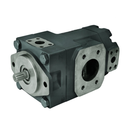
Engineers have not accepted the limit passively. Six successive design changes moved the family’s practical ceiling from 140 bar toward 400 bar in specialized builds.
- Balanced (double-acting) geometry. The two-lobe cam ring cancels radial shaft load, unlocking the 140 to 210 bar industrial band. Fixed displacement only.
- Intra-vane construction. A small vane sits inside a large vane with a bevelled edge. System pressure applied above the small vane reduces net tip loading. Standard in SQP, VQ, and PV2R high-pressure variants.
- Pressure-clamped side plates. Hydrostatic pools force cheek plates against the rotor as pressure rises, closing the axial leakage path automatically.
- Under-vane feed pressure. Correctly set to approximately half the sum of discharge and inlet pressure, the under-vane feed balances vane forces. Over-balancing by a factor of two causes adhesive tip wear; tungsten carbide vanes and cam surfaces solve the resulting damage (US7637724).
- Pitched vanes. The vane sits at an angle instead of square to the ring, changing the force vector and reducing normal load at the tip.
- Hardened materials. Hardened steel vanes, ductile iron or hardened cam rings, and tighter slot clearances raise the contact-stress threshold directly.
Josh Cosford writes in Fluid Power World that the combination of hardened steel, tighter tolerances, and pitched vanes is what let modern fixed-displacement designs exceed 5,000 psi. Even the full ladder has not produced a variable-displacement high-pressure vane pump that gained commercial traction. High-pressure vane is a fixed-displacement story; our variable-displacement vane pump guide covers the compensated designs where they belong. Variable-displacement designs belong to a different pressure-family tier.
The Baseline: Where 2,000 psi Came From
Standard V-series vane pumps are limited to about 2,000 psi or less. That number was never arbitrary. It is the point where the sealing geometry of the baseline design starts working against itself.
For decades this was not just the pump’s limit; it was the industry’s limit. Mobile and industrial circuits were designed around 2,000 psi because that is what the default pump delivered quietly and reliably. The vane family defined what hydraulic systems could do, and the systems followed.
What 2,000 psi buys is worth stating clearly: approximately 140 bar continuous in the 55 to 70 dB(A) noise band, with volumetric efficiency above 92% over a multi-thousand-hour service life. The family was not underpowered for its era. It was optimized for it.
Today the picture is different. Above roughly 250 bar continuous, piston pumps are the default. The vane family’s high-pressure tier lives in the 210 to 300 bar band, where noise and pulsation still matter more than raw pressure capability.
Series That Beat the Vane Pump Pressure Limit
A handful of series pushed through the standard ceiling. Each solved a different part of the problem.
| Series | Rated pressure | What changed | Status |
|---|---|---|---|
| V / standard | ~2,000 psi (~140 bar) | Baseline design | Still sold, widely cloned |
| VQ | 3,000 psi (~207 bar) | Better materials, improved balancing | In service |
| VQH | 3,500 psi (~241 bar) | Enhanced rotor, ductile iron | In production |
| HVQ | 5,800 psi (400 bar) | Redesigned vane loading, materials | Discontinued by Danfoss; clones exist |
| T6 / T67 / T7 | ~240 to 300 bar continuous | Frame-specific engineering | In production |
| SQP / PV2R | ~175 to 210 bar | Intra-vane, low-noise | In production |
Every figure is frame-, displacement-, and fluid-specific. Denison T7 ratings vary by up to 80 bar across frame grades and multi-section configurations; confirm against the manufacturer catalogue for your exact model code. The vane pump pressure rating is not a single number but a function of frame size, displacement, fluid type, and duty cycle.
The HVQ is the cautionary case. It reached 400 bar by changing so much of the pump that it does not interchange with V or VQ installations. Danfoss no longer manufactures it. Clone makers still offer it. If you need 380 bar continuous and a hard noise limit, that lineage is the only vane answer that has ever existed, and provenance matters more there than anywhere else in this market.
Why Designers Accept the Vane Pump Pressure Limit
Push a vane pump past its comfortable envelope, and it starts to behave and sound like a gear pump: more noise, more pulsation, more wear, shorter life. The family’s value proposition is quiet, smooth output in clean, medium-pressure duty. Trading that away for pressure defeats the purpose.
Cosford makes the economic point directly: the low noise and slightly better efficiency that distinguish a vane pump from a gear pump are “hard to justify over a gear pump, in most cases.” Our gear pump vs vane pump comparison covers that trade-off in full.
The commercial ladder follows: basic vane costs less than high-pressure vane, which costs less than piston, including bent-axis designs. Understanding the vane pump pressure limit helps justify when the upgrade to piston makes engineering sense. Above roughly 300 bar continuous, piston is the honest answer.
What This Means for Specifying a Pump
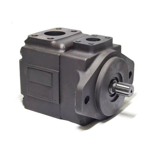
When you specify or replace a vane pump near its pressure limit, five rules apply.
- Never quote a bare pressure number. Quote pressure, speed, fluid, and duty cycle together. Continuous, intermittent, and peak pressure are not interchangeable. Our hydraulic vane pump complete guide defines the three-rating discipline.
- Above 140 bar continuous, you are already in the high-pressure vane tier. Verify the series, not just the listing.
- Above 250 to 300 bar continuous, evaluate piston honestly. The crossover is engineering, not brand loyalty.
- Filtration tightens with pressure. Tip loading makes vane pumps more contamination-sensitive at the top of their range. Our vane pump maintenance guide covers ISO 4406 targets by pressure band.
- Speed matters as much as pressure. The pV factor means a pump rated at 1,200 rpm is not rated the same at 2,400 rpm.
Ready to confirm a rating at your actual conditions? Request a specification-matched quotation with your speed, fluid, and duty cycle, and we will derate the catalogue figure before you order.
Frequently Asked Questions
Why are vane pumps limited in pressure?
Vane pumps are limited because each vane must slide in its rotor slot while maintaining sealing contact with the cam ring. Rising discharge pressure loads the extended vane on its side, increasing tip contact stress, internal leakage, and wear until the pump can no longer hold its rating. The standard industrial ceiling is about 2,000 psi (140 bar) continuous; engineered exceptions reach 3,000 to 5,800 psi.
What is the pressure limit of a vane pump?
Standard vane pumps are limited to about 2,000 psi (140 bar) continuous. Modern high-pressure series reach 3,000 psi (VQ), 3,500 psi (VQH), and in the discontinued HVQ lineage, 5,800 psi (400 bar). Every rating is frame-, displacement-, and fluid-specific.
What is vane tip loading?
Vane tip loading is the force concentrated at the point where each vane presses against the cam ring. As discharge pressure rises, the fully extended vane acts as a cantilever, concentrating hydraulic force into a small contact patch. Contact stress at that patch is the primary physical limit on vane pump pressure capability.
Can a vane pump reach 300 bar?
Yes, in engineered exceptions. Parker Denison T7 D-grade cartridges are rated approximately 250 bar continuous and 300 bar intermittent, subject to derating at your speed and fluid. The Eaton VMQ reaches 293 bar continuous. Standard designs do not reach 300 bar.
Why did hydraulic systems historically run at 2,000 psi?
For decades, 2,000 psi was the standard vane pump’s limit, and the vane pump was the default industrial pump. The system standard followed the pump’s capability rather than the other way around. Modern systems exceed 2,000 psi because materials and designs moved the vane ceiling, and because piston pumps took over the highest-pressure duties.
What is the difference between vane tip loading and radial side load?
Vane tip loading affects every vane pump: it is the force at the vane-cam ring contact. Radial side load affects only single-acting (unbalanced) designs: it is the net hydraulic force on the rotor and shaft caused by asymmetric pressure distribution. Balanced double-acting designs cancel the radial side load but do not eliminate tip loading.
How does heat affect vane pump pressure capability?
Heat from internal leakage thins the hydraulic oil above about 60 °C. Thinner oil leaks faster through the same clearances, generating more heat. This compounding loop reduces volumetric efficiency and can cause rapid failure once the cooler cannot keep up. It is the reason a vane pump near its ceiling fails in hours rather than weeks.
Can a worn vane pump still hold its rated pressure?
Not reliably. Tip wear and cam ring clearance growth increase internal leakage, often past the point where a new cartridge restores performance if the ring itself is deformed. If volumetric efficiency has dropped measurably, inspect the ring before assuming a cartridge rebuild will solve the problem.
Is a vane pump or piston pump better for high pressure?
Below about 250 bar continuous, with a noise or pulsation requirement, vane is often the better choice. Above about 300 bar continuous, or when precise high-power control is required, piston is the correct answer.
Conclusion
The vane pump pressure limit is not a marketing shortcoming or a manufacturing shortcut. It is a mechanical constraint built into the sealing geometry of the family.
The four points that matter most: vane tip loading is the family-wide limit; radial side load is the single-acting limit that balanced designs cancel; six successive design responses moved the practical ceiling from 140 bar to engineered exceptions above 400 bar; and the family trades pressure capability for the quiet, smooth output that justifies choosing vane at all.
If your duty sits below about 250 bar continuous and noise matters, a properly specified vane pump is the right engineering answer. If it sits above, evaluate piston honestly rather than forcing a vane into a duty it was never designed to hold.
Request a specification-matched quotation with your duty cycle, and we will confirm the rated pressure at your speed and fluid before you commit.