A 20 GPM pump at 3,000 PSI needs about 35 hydraulic horsepower. The same machine cycle can often run on 7.
Most hydraulic machines need high flow and high pressure at different moments. A single fixed-displacement pump covers the worst case, so it carries capacity the machine uses only part of the time.
A hi-lo hydraulic circuit splits the job between two pumps. One moves fluid fast; the other builds force. An unloading valve decides when the large pump steps aside.
This guide covers how the circuit works, how to calculate the changeover pressure, and how to set the unloading valve without chatter. It also compares three alternatives.
Our complete guide to two-stage hydraulic pumps covers the pump-level version. This article stays at the system level.
Scope: external two-pump circuits with an unloading valve. Integral two-stage pumps, mobile hi/lo travel circuits, and sump pump switches are different topics.
What Is a Hi-Lo Hydraulic Circuit?
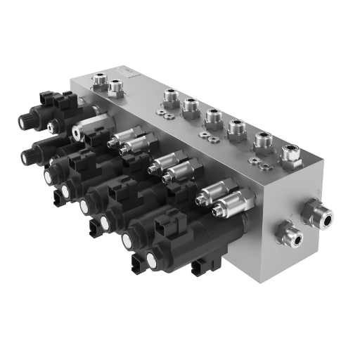
A hi-lo hydraulic circuit uses two pumps on one drive: a high-flow, low-pressure pump for fast movement and a high-pressure, low-flow pump for force. Both pumps supply flow until system pressure reaches a set changeover point. Then an unloading valve dumps the large pump to the tank, and the small pump alone builds pressure.
Search queries use hi-lo hydraulic circuit, hi-lo hydraulic circuit, and high-low hydraulic circuit interchangeably. Some engineers say two-pump hydraulic circuit or double-pump hydraulic circuit; the textbook name is hi-lo pump circuit.
Three elements define the circuit:
- Two pump sections on a common drive.
- A changeover pressure where the large pump unloads.
- An unloading valve with a defined on/off differential.
| What people call “hi-lo” | What it actually is | Scope |
|---|---|---|
| Hi-lo hydraulic circuit | Two pumps plus an unloading valve | This article |
| Two-stage hydraulic pump | One housing, two gear sets, internal unloader | Parent guide |
| Regenerative circuit | One pump, rod-end flow redirected to the cap end | Alternative architecture |
| Mobile hi/lo travel | Two-speed motor or transmission range | Different machine function |
| Hi-lo sump switch | Float switch for a sump pump | Different product |
A hi-lo circuit can use two separate pumps or one integral two-stage pump. The integral pump is more compact and simpler to plumb; the separate-pump circuit gives more freedom in pump types, flow split, and service access.
In 2023, Marta, a design engineer at a press builder in Turin, sized a 75 L/min power unit around a single pump. At 210 bar, it needed about 31 kW. Marta split the flow into 15 L/min at high pressure and 60 L/min at low pressure.
With the changeover at 42 bar, the same cycle ran on a 7.5 kW motor. The power unit shrank by roughly 80%.
For the full family overview, first start with our complete guide to high-pressure vane pumps.
If you’re choosing between a two-pump circuit and an integral pump, request a technical review. We’ll check the duty cycle and valve settings.
How a High/Low Circuit Works, Stage by Stage
- Approach. Both pumps supply flow at low pressure. The actuator moves fast.
- Changeover. Pressure reaches the setpoint. The unloading valve opens and dumps the large pump to the tank.
- Work stroke. The check valve isolates the high-pressure pump. The small pump builds force at low flow.
- Reset. Pressure falls. The unloading valve reseats, and both pumps supply again.
Stage 1: Combined flow, low pressure
At rest, both pumps draw oil from the reservoir. When the directional valve shifts to extend, both pumps feed the cap end of the cylinder. Flow adds, pressure stays low, and the actuator moves fast.
Stage 2: High-pressure pump only
When the load rises, pressure climbs. At the changeover setpoint, the unloading valve opens. The large pump’s flow goes to the tank at low pressure.
A check valve closes to stop the high-pressure pump from backfeeding through the unloaded pump. The small pump continues alone. Flow drops, pressure rises, and force increases.
Reset, retract, and neutral
When the directional valve centers or the cylinder retracts, pressure falls. The unloading valve reseats at its cut-in pressure, and both pumps supply again. With a tandem-center valve, both pumps return to tank at neutral, so no flow crosses the relief valve while the machine waits.
Control variants
Most circuits use a pilot-operated unloading valve that shifts on system pressure. Some use a solenoid valve or pressure switch, so the controller chooses the changeover point. Timed sequencing can add the large pump after a delay and drop it at the motor’s power limit.
Reading the schematic
Look for two pump symbols feeding a common pressure line. The large pump’s outlet passes through the unloading valve. A check valve sits between the small pump and the common line. The main relief valve protects the circuit, and a gauge port lets you measure the changeover pressure.
Our two-stage pump diagram guide shows the internal version. For the pump-level explanation, see how a two-stage hydraulic pump works.
Hi-Lo Circuit Components and Their Job
| Component | Job | Failure symptom |
|---|---|---|
| High-pressure pump | Low flow at high pressure | Weak force, slow work stroke |
| High-flow pump | High flow at low pressure | Slow approach |
| Unloading valve | Dumps the large pump at changeover | No high pressure, or stays in high flow |
| Isolation check valve | Prevents backflow through the unloaded pump | Pressure decay, heat, slow cycle |
| Main relief valve | Caps maximum pressure | Overheating, pressure creep |
| Directional valve | Routes flow to the actuator | Throttling heat, slow cycle |
| Pre-fill valve | Fills a large press cylinder from the tank | Cavitation, slow approach |
| Counterbalance valve | Holds a load | Drift, runaway |
| Reservoir, filter, cooler | Keep the fluid clean and cool | Heat, contamination |
The unloading valve and check valve decide how the circuit behaves. The unloading valve sets the changeover pressure and differential. The check valve keeps the high-pressure pump isolated after the large pump unloads.
If the check valve leaks, the high-pressure pump bleeds back through the unloaded pump. Pressure decays, oil heats, and the work stroke slows. An unloading valve circuit is only as stable as its pilot line and check valve.
The Design Math Behind a Two-Pump Circuit
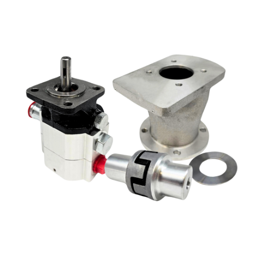
The motor must survive two points: combined flow at the changeover pressure, and high-pressure flow at maximum pressure. Set the hydraulic power at those two points equal.
P_switch = P_max × Q_HP / (Q_HP + Q_LP)
Here P_switch is the changeover pressure, P_max the maximum working pressure, Q_HP the high-pressure pump flow, and Q_LP the low-pressure pump flow.
The hydraulic power formulas are:
- US:
HP = Q (GPM) × P (PSI) / 1714 - Metric:
kW = Q (L/min) × P (bar) / 600
Add efficiency to get input power: input power = hydraulic power / overall efficiency.
Worked example in US units
Take a 20 GPM circuit with a 4 GPM high-pressure pump and a 3,000 PSI maximum.
P_switch = 3,000 × 4 / 20 = 600 PSI.- Combined-flow power at changeover:
20 × 600 / 1714 = 7.0 HP. - High-pressure power at maximum:
4 × 3,000 / 1714 = 7.0 HP. - At 85% overall efficiency, the motor needs 8.2 HP, so a 10 HP motor covers it.
- A single 20 GPM pump at 3,000 PSI would need 35 hydraulic HP, or about 41 HP input.
The hi-lo circuit drops the motor from about 41 HP to 10 HP.
Worked example in metric units
Take a 75 L/min circuit with a 15 L/min high-pressure pump and a 210 bar maximum.
P_switch = 210 × 15 / 75 = 42 bar.- Combined-flow power:
75 × 42 / 600 = 5.25 kW. - High-pressure power:
15 × 210 / 600 = 5.25 kW. - At 85% efficiency, a 7.5 kW motor covers it. A single pump would need about 31 kW input.
| Parameter | Single pump | Hi-lo circuit |
|---|---|---|
| Flow at low pressure | 20 GPM | 20 GPM |
| Flow at high pressure | 20 GPM | 4 GPM |
| Maximum pressure | 3,000 PSI | 3,000 PSI |
| Hydraulic power at peak | 35 HP | 7 HP |
| Motor input at 85% efficiency | ~41 HP | ~8.2 HP |
| Selected motor | 50 HP class | 10 HP class |
The equation assumes a common drive, fixed-displacement pumps, and negligible losses. Add a service factor, and check the result against the relief setting.
Relief and unloading are different settings. The unloading valve sets the changeover, and the relief valve sets the maximum. In a classic hi-lo circuit, the two settings are far apart.
For the full sizing method, see our hydraulic pump sizing guide. To run the numbers for a specific cycle, use the hydraulic pump horsepower calculator.
Setting the Unloading Valve Without Chatter
An unloading valve has two pressures: the off pressure where it unloads the large pump, and the on pressure where it reseats. The difference is the on/off differential.
Bucher Hydraulics lists five differential bands for its DWPB-4N valve: 8–12%, 13–17%, 17–23%, 27–33%, and 37–43%. For fast-to-slow changeover, the 17–23% band is a reasonable starting point. Some valve guides use a reset around 85% of the setpoint.
Too little differential causes chatter: the valve cycles rapidly around the setpoint, pressure fluctuates, and the pump sounds like it is hunting. Too much differential causes a late reset, so the large pump stays offline too long, and the approach is slow.
Three other things cause chatter:
- The pilot line senses pressure downstream of a restriction.
- Air is trapped in the pilot line.
- The check valve leaks, so the high-pressure pump keeps loading the unloaded pump’s outlet.
Commissioning procedure
- Verify the relief setting and pump rotation.
- Install a calibrated gauge at the pump outlet or test port.
- Warm the oil to operating temperature.
- Set the unloading valve to the calculated changeover pressure.
- Set the differential to the manufacturer’s band. Start near 20%.
- Cycle the actuator slowly and record the unload and reload pressures.
- Check motor current at combined flow and at high-pressure work. Neither should exceed the motor rating.
- Repeat the check after the oil is hot. Viscosity changes shift the behavior.
Backpressure and pilot ratio matter. Some valves use a pilot ratio instead of a direct setpoint: a counterbalance cartridge set at 4,000 PSI may begin unloading near 1,000 PSI and be fully unloaded above 1,400 PSI (Sun Hydraulics). Read the datasheet before you assume a linear setting.
Safety comes first. Relieve pressure before adjusting, use lockout and tagout, and follow the ISO 4413 safety standard for hydraulic systems.
In 2022, Erik, the maintenance lead at a recycling plant in Rotterdam, replaced the pump on a baler twice. The baler still overheated and lost pressure at the end of the compaction stroke.
A gauge on the pump outlet showed the unloading valve was set 15 bar too high, and the check valve was leaking. Cleaning the pilot orifice and resetting the valve took an hour. The two pumps had cost about $1,800. The valve fix cost less than $60.
For the full comparison, our vane pump vs. piston pump comparison covers the crossover decision.
Hi-Lo vs Two-Stage Pump vs Regenerative vs Variable Displacement
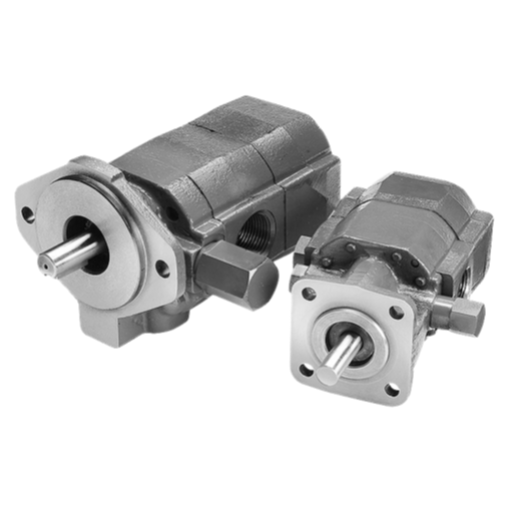
The hi-lo circuit is one of four ways to get fast approach and high force. The right choice depends on the duty cycle, the first-cost budget, and the energy cost.
| Criterion | Hi-lo two-pump circuit | Integral two-stage pump | Regenerative circuit | Variable-displacement pump |
|---|---|---|---|---|
| How it makes speed | Both pumps feed | Both gear sets feed | Rod-end flow joins pump flow | High displacement at low pressure |
| How it makes force | Small pump only | Small gear set only | Reduced force in regen mode | Displacement adjusts |
| Motor size | Much smaller than a single fixed pump | Much smaller | Smaller pump flow | Nearly equivalent to hi-lo |
| Retract speed | Fast | Fast | Unchanged | Depends on control |
| Part-load efficiency | Poor | Poor | Poor | Best |
| Component count | High | Medium | Low | Medium |
| First cost | Medium | Low | Low | High |
| Best application | Large presses, custom circuits | Log splitters, small machines | Extension-only speed | Variable loads, energy savings |
| Main limitation | Valve setup, heat | Envelope, fixed split | Force loss, extension only | Cost, contamination sensitivity |
Hi-lo vs an integral two-stage pump
The principle is the same; the packaging differs. An integral two-stage pump puts both gear sets and the unloader in one housing. The circuit uses two separate pumps and an external valve, which gives more freedom in pump types, flow split, and service access. The integral pump is simpler and cheaper for small machines.
Hi-lo vs. a regenerative circuit
A regenerative circuit re-routes rod-end flow to the cap end. It speeds extension with the same pump flow but reduces force, and it does not improve retract speed. A hi-lo circuit keeps full force and speeds both directions, at the cost of a second pump and valve.
Hi-lo vs a variable-displacement pump
A torque-limiting variable pump can match the motor downsizing without unloading valves. It is better at part load because it reduces displacement instead of dumping flow, but it costs more and is less tolerant of contamination.
Fluid Power World notes that the tandem-pump approach can cut the motor to roughly one-fifth of a single fixed-displacement pump’s requirement. The trade-off: the full cylinder volume passes through the directional valve twice per cycle, which causes throttling losses and heat.
Choose hi-lo when first cost, simplicity, and high-flow/low-pressure speed matter. Choose variable displacement when part-load energy and controllability matter.
When not to use a hi-lo circuit
Skip hi-lo for long holds, highly variable flow, tight speed control, or a duty cycle dominated by partial flow. A variable-displacement or load-sensing pump is usually better there.
Circuit-Level Failure Modes in High/Low Systems
| Symptom | Likely circuit cause | Check | Fix |
|---|---|---|---|
| No high pressure | Unloading valve stuck open, check valve leaking, pilot line blocked | Gauge at pump outlet; inspect valve | Clean or replace the valve |
| Stays in high flow and overheats | Unloading valve stuck closed or set too high | Verify the setpoint | Reset or clean the valve |
| Chatter at changeover | Differential too small, pilot sensing throttled pressure, air in pilot line | Record unload and reload pressures | Adjust the differential; bleed the pilot line |
| Slow cycle | Low-pressure pump worn, inlet restricted, changeover too early, valve undersized | Flow test and pressure gauge | Repair the pump; resize the valve |
| Heat at idle | Valve not fully unloading, relief valve bypassing | Temperature and motor current | Fix the valve or relief setting |
| Pressure decays during hold | Check valve or counterbalance valve leaking | Isolate the circuit | Replace the leaking valve |
These are circuit-level causes. For pump-level symptoms, see our HI/LO hydraulic pump troubleshooting guide.
Where Hi-Lo Circuits Fit Best
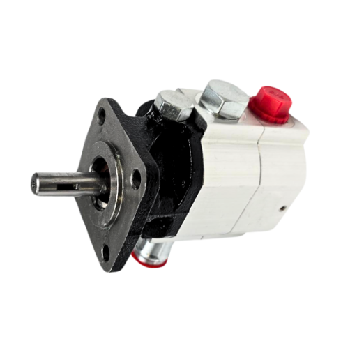
Hi-lo circuits fit cyclic machines that need a fast approach and a short high-force work stroke.
| Application | Typical pressure | Why hi-lo fits | What to watch |
|---|---|---|---|
| Hydraulic press | 200–350 bar | Fast approach, slow pressing | Pre-fill valve, decompression |
| Log splitter | 150–250 bar | Fast extension, high splitting force | Heat, cycle time |
| Baler or compactor | 150–250 bar | Long stroke, high force | Shock, two pressure limits |
| Shear or clamp | 150–300 bar | Fast approach, short work | Duty cycle, valve size |
Large presses often add a pre-fill valve, which fills the cylinder from the tank during the fast approach and closes before the press stroke. Without it, the pump would have to fill the whole cylinder volume and the approach would be slow.
Balers and compactors often use two pressure switches. The large pump unloads at the first limit, which is set by the motor’s power rating. The small pump continues to a higher pressure to finish the stroke.
In 2024, Kenji, an engineer at a scrap baler OEM in Ohio, used the same two-switch sequence on a 40-ton baler. The large pump unloaded at the motor’s power limit, and the small pump finished the compaction stroke.
Cycle time fell by 22%, and the OEM kept the same 15 kW motor. The alternative was a 45 kW single-pump unit and a larger electrical service.
Need help matching a pump split to a press, splitter, or baler cycle? Talk to our engineers about the flow and pressure profile.
Frequently Asked Questions
What is a hi-lo hydraulic circuit?
A hi-lo hydraulic circuit uses two pumps on one drive. A high-flow, low-pressure pump moves the actuator fast. A high-pressure, low-flow pump builds force, and an unloading valve takes the large pump offline at a set changeover pressure.
What is the difference between a hi-lo circuit and a two-stage pump?
A two-stage pump puts both pumping sections and the unloader inside one housing. A hi-lo circuit uses two separate pumps and an external unloading valve. The circuit gives you more freedom in pump types and flow split.
How do you calculate the changeover pressure?
Set the hydraulic power at changeover equal to the power at maximum pressure. The result is P_switch = P_max × Q_HP / (Q_HP + Q_LP). The calculation assumes a common drive, fixed-displacement pumps, and negligible losses.
What pressure should the unloading valve open at?
It should open at the calculated changeover pressure, not at an arbitrary point below the relief setting. The relief valve protects the circuit at maximum pressure. The unloading valve sets the transition from combined flow to high-pressure flow.
Can a hi-lo circuit replace a variable-displacement pump?
Sometimes. A hi-lo circuit is a lower-cost way to shrink the motor on a cyclic machine. A variable-displacement pump is better at part load and gives smoother control, so the duty cycle decides.
What causes an unloading valve to chatter?
Chatter usually comes from too little on/off differential, a pilot line that senses a throttled pressure, air in the pilot line, or a leaking check valve. Start with the differential, then check the pilot line and the check valve.
Is a hi-lo circuit the same as a two-speed circuit?
No. In mobile equipment, a two-speed circuit often changes motor displacement or transmission range. A hi-lo hydraulic circuit uses two pumps and an unloading valve to switch between high flow and high pressure.
Conclusion
A hi-lo hydraulic circuit is an architecture, not a single component. Two pumps share the work. The large pump provides speed at low pressure. The small pump provides force at low flow.
An unloading valve and a check valve manage the transition between them.
Calculate the changeover pressure from the power balance, not from a rule of thumb. The unloading valve’s differential and the check valve decide whether the circuit is stable. Commission the valve with a gauge, warm oil, and a motor-current check.
Hi-lo is a low-cost way to shrink the motor on a cyclic machine, though a variable-displacement pump is more efficient for long holds and part-load, heavy-duty.
If you’re specifying a hi-lo hydraulic circuit, send us the cycle data: approach flow, work flow, maximum pressure, hold time, and retract flow. We’ll help you size the pump split, set the changeover pressure, and select the unloading valve. Contact our engineering team for a technical specification sheet.
A well-set hi-lo circuit does its work quietly: fast where speed matters, strong where force matters, and cool while it waits.