Choose hydraulic filter carts when you need to move a unit between planned jobs. Choose a fixed kidney loop to treat one tank. For either choice, start with the oil, the machine’s cleanliness target, the time available, and how you will check the result.
A running pump and a clear-looking hose don’t tell you whether the reservoir meets its target. If you’re comparing equipment, that gap matters: a cart can move its stated volume while the oil you need to clean remains outside the useful circulation path.
This guide links what you buy to how you check its work. You’ll learn what to ask a supplier, how to plan run time, and which sample can show whether the oil meets its target.
Key Takeaways
- Match portable or fixed duty to the actual maintenance schedule.
- Read micron size, capture efficiency, and test conditions together.
- Use theoretical turnovers to plan time, not to certify cleanliness.
- Accept reservoir condition from comparable samples and the written machine requirement.
Choose hydraulic filter carts or a fixed kidney loop
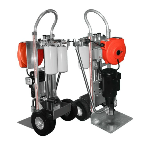
How the independent circuit works
An offline circuit takes oil from a reservoir, or oil tank. Its own pump sends that oil through filters and back to the tank. It adds to the filters in the machine’s main circuit. Schroeder’s offline filtration overview describes stand-alone carts that can operate while the main machine is off, as well as staged filtration and monitoring options.
This separate oil path can let you use time when the machine is off. Can you leave the cart alone? Check the unit’s manual and the site’s rules. Also check whether the tank connection is safe in the planned machine state.
Before comparing models, identify the hydraulic oil cleanliness target required by the machine or component manufacturer. Record the document and application it covers. A target copied from another machine isn’t a defensible purchase requirement.
Match the format to the duty
| Decision | Portable filter cart | Fixed kidney loop |
|---|---|---|
| Intended duty | Move between approved assets or perform scheduled transfer/conditioning | Remain assigned to a reservoir |
| Practical constraint | Travel, connection, cleaning, and operator availability | Installation access, power, and ongoing monitoring |
| Fluid control | Track previous fluid and approved changeover method | Confirm dedicated fluid and materials compatibility |
| Verification | Keep a separate record for each asset and visit | Trend results against the assigned asset’s requirement |
Illustrative scenario: A planner has several reservoirs using the same approved fluid. A shared cart looks convenient, but its schedule must include connection checks and cleaning between assets. A reservoir that needs persistent conditioning may justify a dedicated loop instead; no saving or cleanliness outcome follows from the format alone.
Ask whether the unit can do the job when you need it. A cart used elsewhere cannot keep treating this tank. A fixed loop may be more than you need for a few oil transfers. Include access and staff time in the choice.
Keep the protective working-circuit filters specified by the machine manufacturer. See the distinction between hydraulic pump filter locations and selection before treating reservoir conditioning as a substitute. Debris after a component failure calls for a separate investigation and approved cleaning plan; circulating the tank alone doesn’t establish circuit cleanliness.
Specify the fluid, target, and filtration evidence first
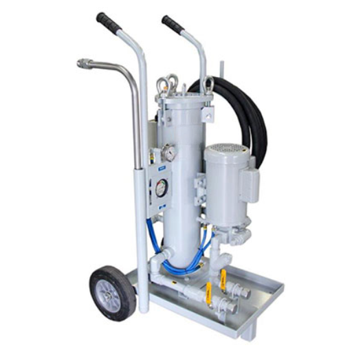
Start with oil identity and operating conditions
Write down the oil’s name, type, viscosity grade, and expected temperature range. Record how much oil the tank holds in use. Viscosity means how strongly a fluid resists flow; its grade alone does not tell you how thick the oil will be at a cold start. Ask the supplier to check that the oil suits every part, from seals and hoses to the pump, filter media, and sensors.
This check also affects a shared cart. In the planner’s example, matching oil labels is just a start. What did the cart last handle, and what oil is still inside it? Use the approved changeover rules.
An empty hose does not prove that a unit is ready for a different oil.
Use this worksheet to flag missing answers:
| Input to record | Evidence to request |
|---|---|
| Machine target and fluid identity | Applicable machine requirement and written compatibility confirmation |
| Actual viscosity range | Fluid viscosity/temperature data and selected-unit operating limits |
| Flow at those conditions | Pump and circuit data covering the proposed duty |
| Particle capture | Size-specific beta rating and test basis for the exact element |
| Contamination loading | Dirt capacity and pressure drop across clean and loaded elements |
| Protection and indication | Relief arrangement, bypass behavior, and indicator instructions |
| Site conditions | Power supply, environment, duty limits, and monitoring requirements |
| Continued maintenance | Exact replacement elements, seals, and service instructions |
Give each blank field an owner and ask for an answer before choosing a model. A flow figure does not prove that the oil suits the unit. A filter rating does not show the limits of the full pump, hose, and filter assembly.
Read micron and beta ratings together
A micron label needs a capture rate. The beta ratio compares counts of particles at or above a stated size. It divides the count before the filter by the count after it. Donaldson’s technical reference explains the ISO 16889 test basis and warns that performance depends on configuration and test conditions.
Capture efficiency is calculated as (1 – 1/beta) × 100%. For beta 200, that is 99.5%; beta 1000 gives 99.9%.
These figures apply to the filter test at the stated particle size. They do not tell you the final code for the oil in your tank. Nor do they tell you which element every machine needs.
Ask which particle size accompanies the beta number, whether the data apply to the proposed element, and what flow and pressure-drop conditions apply. A quote saying only “fine filtration” leaves the technical comparison incomplete.
Check capacity and protection as a system
Capture rate and dirt capacity answer different questions. How well does the element trap particles in the test? How much dirt can it hold before service?
Ask for both sets of data. Also ask how much pressure it takes to push oil through a clean element and one loaded with dirt.
Learn the difference between bypass and pressure relief. A bypass can let oil go around the filter media. Relief limits pressure in the circuit as designed.
Ask which signs show each state on this unit, and what action the manual calls for. Do not treat the two as the same function.
The Donaldson filter-cart brochure, printed in May 2015, illustrates compatibility limits, separate configurations, and pressure indication. Use it to understand the questions, not to adopt historical model settings. Obtain current instructions for the actual unit.
Size hydraulic filter carts from actual flow and available time
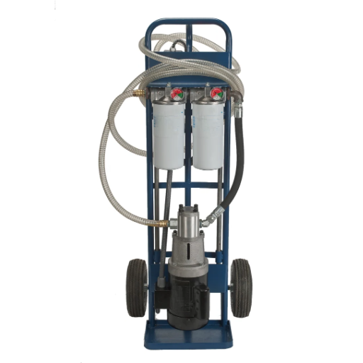
Calculate circulation with consistent units
Start with a turnover calculation to plan the job. A turnover is a volume equal to the oil held in the tank:
N = Q × t / V
Use N for the turnover count and Q for actual flow in litres per minute. Use t for run time in minutes and V for the oil volume in litres. Enter the oil held in use, not the most the empty tank could hold. Check the units before doing the sums.
Illustrative scenario: A reservoir contains 600 L of oil. Assume the cart delivers 12 L/min for 150 minutes. The calculation is 12 × 150 / 600 = 3 nominal turnovers. These inputs are hypothetical, not a measured plant result, and the answer does not predict an ISO cleanliness code.
The same equation can estimate time: t = N × V / Q. That rearrangement only helps after you have a justified planning value for N and a credible operating flow. It doesn’t tell you how many turnovers the machine needs to reach its target.
Why not? Oil mixes. Dirt can keep entering, or wear can create more debris. The tank’s shape also affects which oil reaches the suction point.
The loop may draw oil it has already filtered while other parts of the tank get less flow. “Three turnovers” means the total flow equals three tank volumes; it does not mean each litre passed through three times.
The historical Donaldson brochure qualifies its cleanup-time example by initial cleanliness, contamination ingress, media choice, and other variables. Treat any supplier cleanup estimate the same way: ask for its assumptions and define how the actual result will be checked.
Confirm flow through the operating range
Check flow through the whole loop, not just the pump rating. Thick oil, narrow suction paths, hoses, joints, and a dirty element affect the duty. Ask for data at the coldest planned start.
Check the allowed range as dirt builds up in the filter too. A figure for warm oil and a clean element is only part of the answer.
For the hypothetical reservoir, first establish whether 12 L/min is a supplier assumption or a verified operating value. Record that distinction in the worksheet. If the flow changes during the run, a calculation based on a constant value needs qualification.
Count the time you can really filter. A shift includes travel, access, setup, checks, and taking the unit off the job. Show those tasks in the cart’s schedule.
With a fixed loop, check how long it may run and who will check it. Do not assume it can run without a break.
Use the calculation to compare feasible arrangements. Then use representative samples to determine whether the selected arrangement meets the written requirement. Keep those two decisions separate in the record.
Plan connections and operating checks before starting
Review the oil path and access
Ask the site team to approve the connection points and machine state. Use the unit’s manual and site rules to isolate the system, release pressure, and connect power. This guide cannot tell you that live access is safe. It does not authorize changes to the machine’s oil circuit.
Check where the cart takes oil and where it returns it. If the return feeds straight back into the suction, the unit may keep filtering the same cleaner stream. That leaves doubts about the rest of the tank. Review the layout against the tank shape, internal baffles, normal oil level, and machine state.
Don’t invent a universal distance between the hoses. The useful question is whether the approved layout encourages reservoir circulation without creating another problem. Return routing should also account for air entrainment and disturbance, using the machine and unit instructions.
Before starting, confirm these points:
- The fluid and component materials match the approved specification.
- Suction hose, fittings, and seals suit the duty and show no damage.
- Hoses are supported and protected from kinks, crushing, and traffic.
- Connections, caps, and exposed handling tools are clean.
- Relief, bypass, and differential-pressure indications are understood.
- Sample points and the stop/check response are identified.
Watch conditions that change during the run
Cold oil or a dirty element can raise flow resistance. Check the unit’s limits. Know what to do if a gauge shows abnormal pressure, a hose leaks or collapses, or the unit makes noise or foam. Follow the manual’s stop and check rules.
Don’t defeat a guard or valve to keep oil moving.
In the hypothetical sizing example, an apparent suction restriction would challenge the assumed flow. It would not prove that a bigger pump is needed. Stop and investigate under the approved procedure, then reassess the flow evidence and time estimate.
For a shared unit, log the last oil used, how it was cleaned, and the next asset. Protect hoses and connections when moving or storing it. Use the same care with new oil during transfer. A new container does not prove that the oil inside meets the machine’s target.
Include these practices in broader hydraulic oil maintenance, especially storage and contamination entry. A cart can remove particles, while dirty handling introduces more. Record handling changes so later results can be interpreted alongside the filtration work.
Keep the pre-start record with the job. If a later sample misses the target, this record shows which oil, flow basis, hose layout, and machine state were used. Without it, you may have to repeat those checks before you can judge the filter.
Verify reservoir cleanliness and record the acceptance decision
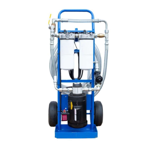
Compare samples that answer the same question
Begin with a representative baseline. Use the hydraulic oil sampling guide to define the location, method, bottle handling, and operating state. Keep follow-up conditions comparable and record any changes. A different sampling point or poorly handled bottle can complicate a trend.
A sample from the filter outlet answers a different question from a tank sample. It can show the state of oil leaving the unit. It cannot prove the state of the whole tank. Label what each sample is meant to show before using a cleaner result to close the job.
Illustrative scenario: The cart outlet appears cleaner than the representative reservoir sample. That difference need not mean the filter failed. Check the sample locations, reservoir circulation, timing, bypass observations, and ongoing contamination sources before choosing the next action. No achieved count or successful repair is assumed in this example.
Compare the tank sample with the written target. If it falls short, record that finding; do not call the job complete. A passing particle count still does not prove the oil is fit for use. Check the other oil tests too.
The guide to interpreting hydraulic oil analysis reports explains why a particle result belongs alongside other findings rather than replacing them.
Investigate a plateau before buying more flow
If sound samples stay above the target, check the basics first. Was the sample taken and handled well? Is it from the right oil and asset? Then check actual flow, oil temperature, the element, signs of bypass, and where oil leaves and returns to the tank.
Next, look for dirt still getting in or debris from wear inside the machine. A particle filter cannot repair a worn part. A bigger cart does not prove that the source of dirt is under control. Ask the maintenance team to review signs of a machine fault.
If the problem is water or oil breakdown, confirm what is wrong and what treatment it needs. Do not assume a particle element will fix it. Check what the unit is designed to do and what the machine’s approved plan allows. A cleaner particle count is not the whole answer.
Save the decision and its limits
Use a completion record that another technician can understand:
| Record field | What to enter |
|---|---|
| Asset and requirement | Machine ID, target, document reference, responsible reviewer |
| Fluid and baseline | Oil identity, baseline sample ID, result, and method |
| Filtration setup | Unit/element identity, connection layout, working volume |
| Operating evidence | Runtime, flow basis, temperature, pressure/bypass observations |
| Changes during work | Element changes, oil additions, interruptions, handling changes |
| Follow-up evidence | Sample ID, location, operating state, comparable result |
| Decision | Meets the stated particle target, remains above it, or inconclusive |
| Next action | Further investigation, other treatment, or scheduled follow-up |
Agree how to accept the work before the run. If you cannot compare the samples, or a required oil test is missing, mark the result “inconclusive.” State what is still needed and who will obtain it. More hours on the cart do not fill that gap.
When the particle result meets the target, record the next check as well. The test shows the state of the sample. It cannot promise that dirt will not enter later. Also follow the machine’s rules before putting it back in service.
Questions to resolve before choosing offline filtration
Why add a kidney loop when the machine already has filters?
A separate loop can filter tank oil while the main circuit is off, where the setup allows. It adds to the filters already in use. Decide whether you need it from the machine’s target, the dirt problem, time available, and sample results. A fitted loop alone proves no result.
How long should a hydraulic filter cart run?
Plan time from the oil volume and actual flow, then test the tank oil against its written target. Mixing, new dirt, the element, and the hose layout affect the result. There is no fixed hours-per-tank rule. Plan the samples first, and log stops or changes during the run.
Can a filter cart remove water or restore degraded oil?
That depends on what the unit is designed to do and the form of water in the oil. A particle rating alone proves no water-removal ability. A cleaner count also cannot show that oil which has broken down is fit for use. Review the other oil tests and approved treatment.
Can the same cart service different hydraulic oils?
Check that each oil suits all parts it will touch. Also assess the oil left inside from the last job, using an approved changeover method. A matching grade alone is not enough. If you cannot control and check the changeover, a unit kept for one fluid may suit the job better.
Can reservoir filtration replace flushing after component failure?
Filtering the tank does not prove that lines, valves, cylinders, and other parts are free of debris. After a failure, use the machine maker’s rules for finding the cause, cleaning, and checking the system. A cart may be part of that plan; tank flow alone does not prove a flush is complete.
Before choosing equipment, finish these three tasks:
- Complete the fluid-and-duty worksheet and resolve missing supplier data.
- Name the machine’s target and plan a representative sample.
- Use the oil-analysis guide above to review the results, record the decision, and set the next check.