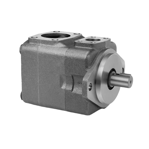
A desalination plant in the Gulf runs its feed pumps at 70 bar, twenty-four hours a day, for years between overhauls. A waterjet cutting cell a hundred meters away drives water through a sapphire orifice at 60,000 psi. A chemical plant meters a corrosive additive drop by drop into a reactor stream. Three different duties, three different industries, and in each case the pump that survives the work is the same family: the plunger pump.
You already know that pistons and gears give up well below these pressures. What you may not know is exactly why the plunger pump wins, how to size one correctly, and what to verify before you sign a purchase order.
This guide answers all three. You will learn what a plunger pump is and how it produces flow, how its types and specifications differ, and how to size, install, maintain, and source one for high-pressure applications. Every section carries numbers, because a pump specification you cannot measure is a specification you cannot trust.
What Is a Plunger Pump?
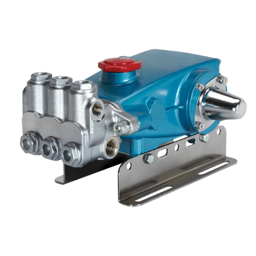
A plunger pump is a reciprocating positive-displacement pump in which a smooth, precision-ground plunger reciprocates through a stationary seal in the pump head. That single design choice, a moving plunger through a fixed seal rather than a seal travelling with the piston, is the reason plunger pumps own the extreme high-pressure end of fluid transfer.
The pump splits into two functional halves. The power end converts rotary drive into reciprocation using a crankshaft, connecting rods, and crossheads. The fluid end does the pumping: a manifold, one or more plungers, inlet and discharge check valves, and the packing that seals each plunger.
Terminology note. In hydraulic fluid power, “plunger pump” is sometimes used loosely for a piston-type hydraulic pump that circulates oil in a closed circuit. This guide covers the other meaning: the process plunger pump used for water, chemicals, and process fluids at extreme pressure. For the hydraulic oil-circulating family, see our guide to hydraulic axial piston pumps.
Plunger pumps are almost always single-acting: one pumping stroke per plunger per revolution. They are compact, mechanically simple at the fluid end, and scalable from a few liters per minute to thousands of gallons per minute when arranged in parallel banks.
How Does a Plunger Pump Work?
The plunger pump’s working principle follows a two-stroke cycle driven by the rotation of the crankshaft. Understanding each stroke explains both the pump’s strengths and its installation requirements.
The Suction Stroke
As the crankshaft rotates, the connecting rod pulls the crosshead and plunger backward out of the fluid chamber. Chamber volume increases, pressure drops, and the inlet check valve opens. Fluid flows in from the suction manifold to fill the growing cavity. The discharge valve stays shut under its spring and the downstream line pressure.
The Discharge Stroke
The crankshaft continues its rotation and pushes the plunger forward. Chamber pressure rises, the inlet valve snaps closed, and once chamber pressure exceeds discharge line pressure, the discharge valve opens. Fluid is ejected into the manifold under pressure.
The cycle repeats once per revolution per plunger. The plunger never rotates and never changes direction mid-stroke; it simply slides back and forth through the packing.
Why the Stationary Seal Matters
The defining feature is that the seal does not move. In a piston pump, the seal travels with the piston inside a cylinder bore, so the bore surface wears and the seal must seal against a moving, wearing wall. In a plunger pump, the packing is fixed in the stuffing box, and the plunger slides through it.
That geometry produces three consequences:
- Higher pressure ceilings. The seal is supported by a static housing, not by a moving piston, so it holds far greater pressure without extruding.
- Longer plunger life. A smooth, hard plunger surface (often ceramic or coated) resists abrasion better than a piston’s sealing surfaces.
- More stable pressure. Plunger pumps hold discharge pressure consistently because the packing does not deform with load.
A Pump Produces Flow, Not Pressure
One point trips up first-time buyers: a plunger pump generates flow, not pressure. Pressure is the resistance the system presents to that flow. If you deadhead the discharge, pressure rises until something yields, which is why every plunger pump needs a relief valve on the discharge line.
Flow, by contrast, is set by the pump’s geometry and speed. It is directly proportional to plunger area, stroke length, number of plungers, and crankshaft speed.
Why Plunger Pumps Are Not Self-Priming
Plunger pumps cannot lift fluid on their own. The inlet check valve needs positive pressure to open and to keep the chamber full during the suction stroke. In practice, this means plunger pumps require flooded suction or a booster pump, with most designs calling for roughly 60 to 70 psi of positive inlet pressure. Higher inlet pressures are permitted on some heavy-duty designs. Run a plunger pump dry, and you destroy the packing and score the plungers within minutes.
Types of Plunger Pumps
Plunger pumps are classified along four independent axes: action, cylinder count, drive, and valve design. Knowing all four prevents the most common specification mistake, which is confusing cylinder count with action.
By Action
- Single-acting: one pumping stroke per plunger per revolution. Almost every plunger pump is single-acting.
- Double-acting: fluid pumped in both directions of plunger travel. This is common on piston pumps but rare on plungers, because the stationary seal cannot easily be arranged on both faces.
By Cylinder Count
Cylinder count is the single most consequential configuration choice for flow smoothness and service logistics:
| Configuration | Plungers | Pulses per Revolution | Relative Flow | Service Points |
|---|---|---|---|---|
| Simplex | 1 | 2 | Lowest | 1 |
| Duplex | 2 | 4 | Low | 2 |
| Triplex | 3 | 6 | Medium-high | 3 |
| Quintuplex | 5 | 10 | High | 5 |
| Septuplex | 7 | 14 | Highest | 7 |
More plungers raise flow for a given size and speed while smoothing the discharge. The trade-off is weight, footprint, and more wear points to service.
By Drive
- Direct-coupled: motor or engine coupled straight to the crankshaft. Simplest and most efficient at moderate speeds.
- Belt drive: flexible speed matching and shock absorption, common on cleaning equipment.
- Gear-reducer: allows a slower crankshaft speed from a fast prime mover, important for high-pressure duty.
- Air-driven and hydraulic-driven: used where electric or engine drive is impractical or where the drive doubles as an intensifier.
By Valve Design
- Valved: spring-loaded inlet and discharge check valves. The standard design for high-pressure process duty.
- Valveless: typically used in metering and dosing applications where precise, low-volume delivery matters more than raw pressure.
Plunger Pump vs Piston Pump
The plunger pump vs piston pump difference comes down to one mechanical fact: where the seal sits.
| Feature | Plunger Pump | Piston Pump |
|---|---|---|
| Seal location | Stationary, in the pump head | Moves with the piston in the bore |
| Typical pressure range | 100 to 10,000 psi; up to 100,000 psi (intensifier) | 100 to 1,200 psi |
| Volumetric efficiency | ~85 to 95%, rises with pressure | ~85 to 90%, best at lower pressure |
| Priming | Not self-priming; needs flooded suction | Self-priming; mechanically actuated inlet valve |
| Inlet requirement | ~60 to 70 psi positive inlet | Can draw suction |
| Wear surface | Plunger surface against fixed packing | Bore wall against moving seal |
| Service life under high pressure | Longer, more stable pressure | Shorter at high pressure |
| Best suited to | Extreme pressure, process fluids | Lower pressure, self-priming duty |
Because the plunger’s seal is stationary, it resists extrusion at pressures that would destroy a moving piston seal. Because the piston’s inlet valve is mechanically actuated, it self-primes where a plunger cannot.
Choose a plunger pump when pressure is high, inlet conditions are controlled, and service life matters. Choose a piston pump when the pump must self-prime or when pressure stays moderate.
Need a specification matched to your duty? LOYAL INDUSTRIAL supplies multiple pump families and can recommend the plunger pump configuration that fits your pressure, flow, and fluid. Request a technical specification sheet.
Plunger Pump Specifications: Pressure, Flow, Plunger Diameter & Speed
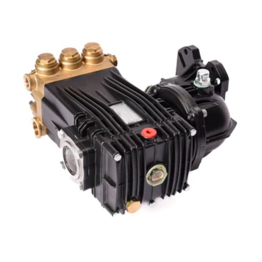
Plunger pump specifications cluster around four variables: pressure, flow, plunger diameter, and speed. Each one constrains the others.
Pressure
Pressure capability depends on construction and application:
| Application Band | Typical Discharge Pressure |
|---|---|
| Chemical metering and dosing | 200 to 2,000 psi |
| Reverse osmosis / desalination feed | 800 to 1,200 psi (55 to 80 bar) |
| Car wash and light cleaning | 1,000 to 3,000 psi |
| Industrial surface preparation | 5,000 to 20,000 psi |
| Oilfield injection and well service | to ~20,000 psi |
| Waterjet cutting (intensifier) | 40,000 to 100,000 psi |
The upper limit for a single plunger stage sits near 4,000 bar (about 58,000 psi) before diminishing returns and material limits take over. Above that, waterjet systems use an intensifier to multiply pressure rather than a single-stage pump.
Flow
Flow comes from plunger bore area multiplied by stroke, multiplied by the number of plungers, multiplied by speed. The geometric displacement per revolution is simply plunger area times stroke times plunger count.
Plunger Diameter and Stroke
Plunger diameter and stroke trade off directly against pressure. A larger plunger moves more fluid per stroke but develops less pressure for a given rod load; a smaller plunger does the opposite. High-pressure duties therefore use small plungers with long strokes, while high-flow, low-pressure duties use larger plungers. Plunger load equals area times pressure, so a small increase in diameter raises rod and bearing loads sharply at high pressure.
Speed
Plunger pumps run slowly compared with rotary pumps. Crankshaft speed is typically 600 rpm or lower, and most high-pressure units run between 300 and 500 rpm. Slower speed reduces plunger-pass frequency, wear, and pulsation, but requires belt or gear reduction from a standard motor.
Efficiency and Materials
Volumetric efficiency for a healthy plunger pump runs about 85 to 95%, and it tends to rise as discharge pressure increases, which is the opposite of what happens in rotary pumps. Fluid-end materials are chosen for the process: brass, cast iron, ductile iron, or stainless steels (304, 316, duplex) for the manifold and valves, ceramic or ceramic-coated plungers for abrasion resistance, and packing or seal materials such as NBR, FKM, EPDM, and PTFE matched to the fluid chemistry and temperature.
How to Size & Select a Plunger Pump
Sizing a plunger pump means matching flow, pressure, cylinder count, and inlet conditions to the duty. Follow this sequence.
1. Define Required Flow
Start from the actuator or process demand, then add a margin of 10 to 20% for wear and slip. Never size to the exact duty; a pump running flat out from day one has no headroom as packing and valves wear.
2. Calculate Geometric Flow
For a single-acting pump, calculate theoretical flow as:
Q (L/min) = (A × s × n × m) ÷ 1,000,000
where A is plunger area (mm²), s is stroke (mm), n is crankshaft speed (rpm), and m is the number of plungers. Multiply by volumetric efficiency for the delivered flow.
3. Calculate Brake Horsepower
Required drive power follows the standard reciprocating relation:
BHp = (GPM × PSI) ÷ 1543
Select the drive motor or engine with a service factor above this figure.
4. Check Plunger Load
Plunger load drives crankshaft, bearing, and rod sizing:
L = A × P
where A is plunger area (in²), and P is discharge pressure (psi), giving load in pounds-force per plunger. This is why high-pressure plunger pumps use heavy crankshafts and large bearings.
5. Verify Inlet Conditions
Confirm flooded suction or a booster delivers the required positive inlet pressure, typically 60 to 70 psi for many designs. Check the suction line for NPSH margin. This step is unique to plunger pumps and is the one buyers skip most often.
Worked Example: Triplex Pressure-Washer Pump
Consider a triplex pump with a 25 mm plunger, 50 mm stroke, running at 500 rpm, to deliver 5,000 psi.
- Plunger area: A = π/4 × 25² = 491 mm²
- Geometric flow: Q = (491 × 50 × 500 × 3) ÷ 1,000,000 = 36.8 L/min (9.7 GPM)
- At 92% volumetric efficiency: Q ≈ 33.9 L/min (9.0 GPM)
- Brake horsepower: BHp = (9.0 × 5,000) ÷ 1543 ≈ 29.2 BHp
- Plunger load: A ≈ 0.76 in², so L = 0.76 × 5,000 ≈ 3,800 lbf per plunger
That final figure shows why a 5,000 psi triplex pump cannot use a light crankshaft. Three plungers, each imposing 3,800 lbf, load the crank and bearings with over 11,000 lbf every revolution.
If you are sizing across pump families, the universal hydraulic pump sizing guide and our hydraulic pump horsepower calculator cover the general case.
Sizing across duty cycles? Send us your flow, pressure, and fluid details and our engineers will confirm the configuration before you commit. Contact for industrial solution consultation.
Plunger Pump Applications by Industry
Plunger pumps appear wherever fluid must be moved at pressure that rotary pumps cannot reach. The table below maps the common duties.
| Industry / Duty | Typical Pressure Band | Why a Plunger Pump |
|---|---|---|
| Pressure washing and surface prep | 1,000 to 20,000 psi | High pressure with controlled flow and simple fluid end |
| Hydro-blasting, sewer jetting, descaling | 3,000 to 20,000 psi | Abrasion-tolerant valves and plungers |
| Waterjet cutting and intensifiers | 40,000 to 100,000 psi | Pressure multiplication via intensifier geometry |
| Reverse osmosis and desalination | 55 to 80 bar continuous | Stable high pressure and continuous-duty construction |
| Chemical injection and metering | 200 to 2,000 psi | Precise, repeatable low-volume delivery |
| Oil and gas (water/CO₂ injection, cementing, well service) | to ~20,000 psi | API 674 duty, large plungers, heavy power end |
| Food and beverage (homogenization, CIP) | 1,000 to 10,000 psi | Sanitary materials and precise pressure control |
| Mining (flushing, slurries) | 1,000 to 10,000 psi | Abrasion-resistant fluid-end materials |
| Hydrostatic testing | to 10,000+ psi | Stable, settable pressure for test loops |
| Vehicle and industrial cleaning | 1,000 to 5,000 psi | Tough, serviceable, cost-effective at volume |
Each application picks the plunger pump for a specific property. High-pressure cleaning needs pressure with controlled flow. Metering needs repeatable displacement. Injection and well service need API-rated construction and a heavy power end.
High-Pressure Plunger Pumps: Cleaning, Waterjet, RO & Injection
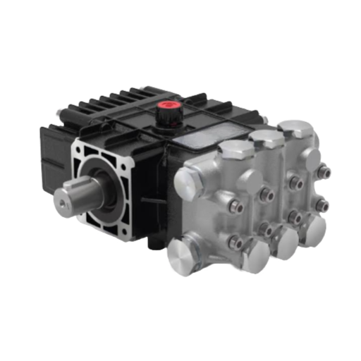
The highest-value plunger pump duties sit at the extreme-pressure end. Understanding the tiers clarifies both the technology and the procurement.
Cleaning Tiers
- Car wash and light cleaning: 1,000 to 3,000 psi
- Commercial cleaning: 3,000 to 5,000 psi
- Industrial surface preparation: 5,000 to 20,000 psi
- Waterjet cutting: 40,000 to 100,000 psi
Above roughly 10,000 psi, plunger pumps pull decisively ahead of other positive-displacement designs. Their stationary seal holds pressure that would extrude a moving piston seal or overload a diaphragm.
Waterjet Intensifiers
A waterjet intensifier multiplies pressure using two plungers of different diameters on a shared rod:
P_water = P_oil × (D_large ÷ D_small)²
If a 100 mm hydraulic plunger drives a 25 mm water plunger, the area ratio is 4, and the squared ratio is 16. Hydraulic oil at 3,000 psi therefore produces about 48,000 psi of water pressure. This is one of the few places where a plunger pump is driven hydraulically rather than by a motor or engine.
Reverse Osmosis and Desalination
Seawater reverse osmosis runs its high-pressure feed pumps continuously at 55 to 80 bar. Continuous duty, not just peak pressure, drives the design: heavy crankshafts, generous lubrication, and seals rated for constant operation. Energy-recovery devices are usually integrated so the concentrated brine stream recovers pressure and cuts pump power.
Case in point. A Gulf desalination train standardized on quintuplex plunger feed pumps running 24 hours a day. The five-plunger layout spread the load across a heavier, smoother power end, and the smooth discharge let the operators size smaller pulsation dampeners. The pumps reached overhaul intervals measured in years, not months, because the duty cycle was matched to a continuous-rated pump rather than an intermittent cleaning unit.
Chemical Injection and Metering
Chemical injection favors simplex or duplex plunger designs that deliver very low flows, often measured in milliliters per minute, with precise stroke adjustment. Displacement control, not pressure, is the objective, so metering accuracy dominates the specification.
Duty-cycle discipline matters throughout this section. An intermittent-rated cleaning pump used on continuous duty will fail early.
Plunger Pumps vs Other Positive-Displacement Pumps
A plunger pump is rarely the only option, so selection should be comparative.
vs Diaphragm Pumps
Diaphragm pumps isolate the fluid behind a flexible membrane and have no packed gland, which suits hazardous, corrosive, or ultra-pure fluids. Plunger pumps reach far higher pressures and, once the controlled leak path of the packing is acceptable, deliver more stable pressure and better volumetric efficiency.
vs Gear and Vane Pumps
Gear pumps and vane pumps are rotary hydraulic families that produce smooth, continuous flow, tolerate contamination, and cost less, but their pressure ceilings sit far below plunger pumps. They suit hydraulic circuits and fluid transfer up to a few hundred bar. Plungers suit process fluids at extreme pressure. See our guides to hydraulic gear pumps and the broad types of hydraulic pumps for the rotary families.
Choose a Plunger Pump When…
- Discharge pressure is high (roughly above 1,000 psi and rising).
- You can provide flooded suction or a booster.
- You need stable, repeatable pressure or precise metered flow.
- The fluid is clean to mildly abrasive and compatible with packing materials.
Choose Something Else When…
- The pump must self-prime (use a piston pump).
- The fluid is hazardous or must not leak at all (use a diaphragm pump).
- Pressure is moderate and smooth continuous flow matters most (use a gear or vane pump).
Installation, Priming & Piping Requirements
Installing a plunger pump correctly is mostly about the inlet.
- Flooded suction or booster: provide the positive inlet pressure the pump needs, typically 60 to 70 psi, higher where the design permits.
- Never run dry: loss of inlet fluid destroys packing and scores plungers quickly.
- Size suction piping for NPSH: keep suction lines short, wide, and free of high points where gas can collect.
- Fit a relief valve: protect the discharge line against deadhead conditions.
- Use a pulsation dampener or accumulator: place it close to the discharge to smooth flow ripple.
- Align the drive: check coupling alignment and belt tension to avoid bearing and crankshaft wear.
- Purge and first-start gently: run at reduced speed and pressure, confirm fluid at the inlet, then bring the pump up to duty.
- Protect for lay-up: drain and add antifreeze for storage, and follow the manufacturer’s preservation steps.
Plunger Pump Maintenance: Packing, Plungers & Lubrication
Most plunger pump failures trace back to the packing, the plungers, or lubrication. A disciplined program prevents the majority of them.
Packing and Seal Program
- Gland tension: with the plunger in place, tighten the gland hand-tight plus about a quarter turn to seat the packing, then back it off roughly three-quarters to seven-eighths of a turn. Compression of around 0.040 in is a common target.
- Slight drippage is correct: an airtight seal is not desirable with many Kevlar or PTFE packings. A small, controlled drip lubricates the plunger; a dry, over-tightened gland wears both packing and plunger.
- Run-in re-check: inspect gland tension after the first 2 to 3 hours of running and re-adjust.
- Replace, don’t over-tighten: when leakage stays high, renew the packing rather than compressing it further.
Plunger Inspection
- Scoring and wear: abrasives, aggressive chemicals, and thermal shock score the plunger surface and accelerate packing wear.
- Ceramic handling: ceramic and ceramic-coated plungers resist abrasion but are brittle. Handle and install without impact.
- Replace on poor finish: once the surface finish degrades, packing life collapses, so renew the plunger at the same time as the packing.
Valves, Lubrication, and the Calendar
- Valves and seats: inspect inlet and discharge check valves and their seats for erosion and correct sealing.
- Crankcase oil: change at roughly 500 hours or three months, whichever comes first.
- Water-in-crankcase prevention: a worn oil seal or V-packing lets process fluid travel along the plunger rod into the crankcase. Monitor for milky oil and address the seal before the crankcase and bearings are affected.
- Lubrication rate: double the lubrication rate for the first 24 hours after repacking, then return to normal.
- Calendar: daily check of leakage and inlet pressure, weekly check of gland tension and oil level, annual overhaul of valves, packing, and plungers.
Plunger Pump Troubleshooting: Symptoms, Causes & Fixes
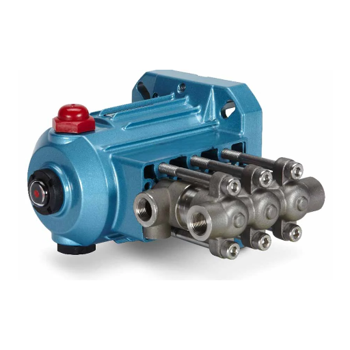
When a plunger pump misbehaves, the symptom usually points to a small set of causes. Use the matrix below to work from symptom to fix.
| Symptom | Likely Causes | First Checks |
|---|---|---|
| Low or no pressure | Worn nozzle, air leak, worn valves or seats, clogged suction filter, insufficient NPSH, worn seals | Verify inlet pressure, inspect valves and seats, check seals |
| Leaking at stuffing box | Worn V-packing, worn plunger or sleeve, incorrect gland tension | Re-tension gland, then replace packing if leakage persists |
| Knocking noise | Worn bearings, loose connecting rods | Stop the pump and inspect the power end before further running |
| Suction noise or cavitation | NPSH not met, restricted inlet | Increase inlet pressure, clear suction line |
| Squealing or screeching | Belt slip | Check and adjust belt tension |
| Hot packing / overheating | Insufficient lubrication, over-tightened gland, wrong packing | Re-check lubrication rate and gland tension, confirm packing grade |
| Water in the crankcase | Worn oil seal or V-packing letting fluid along the rod | Replace the seal and packing, change the oil |
| Oil leaks near crankcase | Worn seals or gaskets | Replace seals, check crankcase fasteners |
| Excessive pulsation | Insufficient NPSH, sticking or worn valves, discharge piping resonance | Verify inlet, service valves, resize or relocate dampener |
Field signatures shorten diagnosis. Suction noise almost always means NPSH is not met. Knocking points to the power end. A screech points to the drive. Repair-versus-replace depends on how many fluid-end parts are worn; once plungers, packing, and valves are all at end of life, a rebuild kit is usually the economical path.
Facing repeated failures? Send us the symptom and duty details and we will help identify the cause and the right replacement. Contact for industrial solution consultation.
Sourcing Plunger Pumps: OEM Manufacturers & Factory-Direct Suppliers
Sourcing follows the same discipline as sourcing any critical component: verify, document, and test.
What to Verify in a Supplier
- Performance testing: every unit should be pressure- and leak-tested to rated conditions, with results available.
- Quality system: ISO 9001 certification, and API 674 (reciprocating positive-displacement pumps) or API 675 (metering) where the duty requires it.
- Material certificates: traceable certificates for manifold, valve, and plunger materials.
- Consumables: confirm packing, plungers, valves, and seats are readily available.
- Warranty and lead time: clear terms for both standard and custom pumps.
Why “Interchangeable” Claims Need Checking
A pump that matches the footprint is not necessarily interchangeable. Verify these before accepting a drop-in claim:
- Mounting and flange dimensions
- Plunger diameter and stroke
- Valve seat type
- Crankcase rating and rotation direction
A matching bolt pattern with the wrong plunger diameter or stroke will change flow and pressure, and the error may not show until the pump is running.
The RFQ Data Set
A complete request gets a correct quote the first time. Provide:
- Fluid and chemistry, including concentration and temperature
- Required flow and discharge pressure
- Fluid temperature range
- Abrasiveness and solids content
- Duty cycle (intermittent or continuous)
- Drive preference (direct, belt, gear-reducer, engine, air, hydraulic)
- Inlet conditions and available flooded suction pressure
- Required standard (API 674, API 675, or general duty)
- Materials of construction
- Mounting and port positions
Cost Structure and OEM Options
China factory-direct suppliers typically undercut branded pumps by removing intermediary markups, provided the quality evidence is real. Look for multi-stage inspection, 100% pressure and leak testing, and material verification. For equipment builders, OEM and private-label options let you specify plunger diameter, ports, and branding.
Case in point. A blasting-equipment assembler bought “interchangeable” replacement pumps on footprint alone. The plungers were 2 mm smaller than the originals, flow dropped, and operators compensated by over-speed-ing the drive, which shortened packing life. Re-specifying against plunger diameter and stroke, not just bolt pattern, restored performance and service life.
When specifying mounting, our reference to SAE mounting and port standards helps confirm interface dimensions.
Sourcing at scale? Request a technical specification sheet and OEM quotation tailored to your duty, fluid, and mounting. Request OEM plunger pump specification and quotation.
Frequently Asked Questions
What is a plunger pump?
A plunger pump is a reciprocating positive-displacement pump in which a smooth plunger reciprocates through a stationary seal in the pump head. The fixed seal allows the pump to hold pressures above 1,000 psi and up to 100,000 psi in intensifier applications.
How does a plunger pump work?
A crankshaft drives the plunger backward to open the inlet valve and draw fluid into the chamber, then forward to close the inlet, open the discharge valve, and eject fluid under pressure. The cycle repeats once per revolution per plunger.
Are plunger pumps self-priming?
No. Plunger pumps are not self-priming and require flooded suction or a booster pump, typically providing 60 to 70 psi of positive inlet pressure. Running one dry damages packing and plungers.
What is the maximum pressure of a plunger pump?
Single-stage plunger pumps reach roughly 4,000 bar (about 58,000 psi). Waterjet intensifiers push beyond that, reaching 100,000 psi by multiplying oil pressure across a larger-to-smaller plunger area ratio.
What is the difference between a plunger pump and a piston pump?
In a plunger pump, the seal is stationary in the pump head, and the plunger slides through it, giving a higher pressure ceiling and longer life. In a piston pump, the seal moves with the piston in the bore, which self-primes but limits pressure.
What is a triplex plunger pump?
A triplex plunger pump has three plungers on a common crankshaft, producing six pulses per revolution. It balances flow, pulsation, and service access, which makes it the default for high-pressure cleaning and process duty.
How do I size a plunger pump?
Calculate required flow from the duty plus a 10 to 20% margin, then compute geometric flow as plunger area times stroke times speed times plunger count. Check brake horsepower with BHp = (GPM × PSI) ÷ 1543 and confirm flooded-suction inlet conditions.
How often does a plunger pump need maintenance?
Inspect daily for leakage and inlet pressure, re-check gland tension after the first 2 to 3 hours of running, change crankcase oil at about 500 hours or three months, and overhaul valves, packing, and plungers annually or on condition.
How much does a plunger pump cost?
Cost depends on pressure rating, cylinder count, materials, and drive. Small cleaning pumps sit at the low end, while continuous-duty, API-rated, or intensifier pumps command a premium. Factory-direct sourcing removes intermediary markups.
Plunger pump vs diaphragm pump: which should I choose?
Choose a plunger pump for high pressure, stable discharge, and precise volumetric dosing of clean fluids. Choose a diaphragm pump for hazardous, corrosive, or slurry-laden fluids where a packed-gland leak path is unacceptable.
Conclusion
A plunger pump is the design that owns extreme-pressure fluid transfer, and it comes down to one feature: a stationary seal with a smooth plunger running through it. Everything else, from the pressure ceiling to the maintenance program, follows from that geometry.
The key takeaways:
- Plunger pumps generate flow, not pressure, and produce stable high pressure where pistons and rotaries cannot.
- They are not self-priming and always need flooded suction or a booster.
- Sizing starts with flow, then pressure, cylinder count, and the inlet check, and the math is straightforward once you have the numbers.
- Most failures trace to packing, plungers, or lubrication, all manageable with a consistent maintenance program.
If you are specifying a plunger pump, the fastest path to a correct decision is accurate duty data and a supplier who tests what they ship. LOYAL INDUSTRIAL PTE. LTD. supplies plunger pumps and multiple pump families, so the recommendation you get is matched to your system rather than to a single product line.
Request a technical specification sheet or contact our engineers for an OEM plunger pump recommendation built around your flow, pressure, fluid, and mounting requirements.