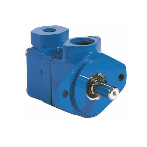
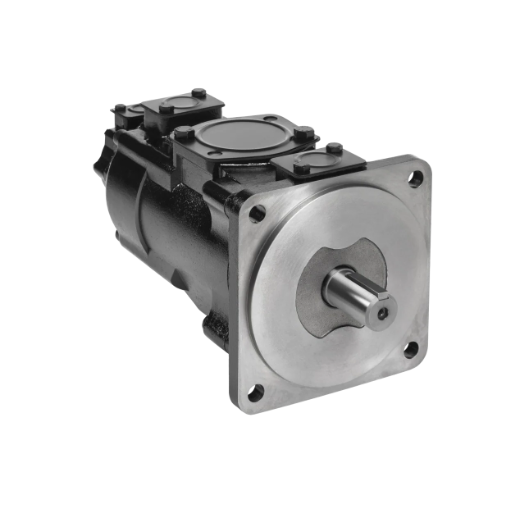
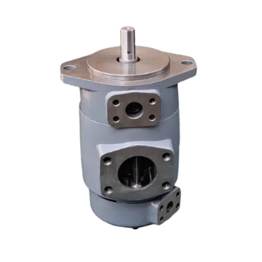
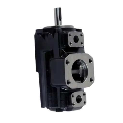
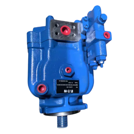
Triple vane pump troubleshooting starts with the three displacement codes on the nameplate, not with the gauge. Each code carries its own pressure and flow rating, so the same reading can be a fault at one port and normal at another. Read the codes first, then judge the gauge against the port it belongs to.
Every troubleshooting sheet in the search results was written for a pump with one outlet. They tell you to check flow, check pressure, check the relief. On a three-section pump, those three instructions point to three different answers, and none of the sheets says which one you are looking at.
This page covers industrial triple vane pumps: Parker and Denison T6 and T67, Vickers VQ with a V10 cover, and Tokyo Keiki SQP. The Ford and automotive units that share the phrase are different machines and use a different method. If the stacking order is new to you, how a triple vane pump is built has the cutaway view.
What follows is the order of decisions, the published numbers each decision needs, and the readings that look like failures but are not. If the pump is already off the machine and you have the three codes, send them with the gauge readings, and the numbers below can be checked against your build.
Key Takeaways
- The weakest section on a triple is a code, not a position. Two Vickers 2520VQSV10 builds differ by one centre code, and the lowest-rated port moves from the cover end at 172 bar to the middle at 140 bar.
- The same pump family disagrees with itself across catalogues: a Parker T67EDC triple rates P1 at 240 bar, P2 at 250 bar and P3 at 275 bar, while a Tokyo Keiki SQP211 rates the middle and cover sections 35 bar below the shaft end.
- A cover section that delivers 62.4% of its zero-pressure flow at its rated pressure is behaving as printed. On a T67EDC with a C 005 cover, 16.1 L/min at 275 bar is the catalogue figure, not wear.
- Parker refuses to publish a flow for a 003 cover section at 275 bar because internal leakage exceeds 50% of theoretical flow, so a reading near half of nominal is documented behaviour.
- On a Vickers triple with a flow-control or priority cover, the integral relief protects only the cover outlet. The shaft-end and centre sections need external valves, which makes the external valve the first suspect when P1 or P2 is low.
Why a triple pump breaks the usual troubleshooting method
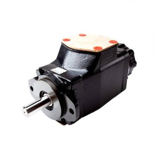
A single vane pump gives you one pressure rating, one flow curve, and usually one relief valve. A symptom maps to a short list of causes, and the list is the same list every guide prints. That’s why the generic pages work, and why they stop working here.
A triple has three cartridges on one shaft, three outlets, and on some builds three different relief arrangements. The Vickers design guide is blunt about the consequence: “Operating pressures of the shaft-end and center pumps of double and triple pumps must be controlled by separate, external relief valves” (Eaton 353, p. 12).
Vickers makes the wider point in its service information: “It should always be remembered that many apparent pump failures are actually the failures of other parts of the system” (p. 10). On a triple, “other parts” includes the two outlets you were not looking at.
One thing to state plainly before the steps. No catalogue in this source set publishes a three-section diagnostic procedure. The sequence below is engineering reasoning applied to published failure data and published ratings. It isn’t an OEM method, and no manufacturer should be credited with it.
The consequence of all this is a single rule that governs the rest of the page: a symptom is not a measurement until it has a port. “Down on pressure” is not data. “P2 reads 186 bar hot against a 250 bar ceiling” is data.
Triple vane pump troubleshooting starts with the model code
The model code is the map from position to code, and the three families write it differently.
Tokyo Keiki prints it field by field in catalogue B3. On B3-1, field 3 is “Shaft end pump displacement”, field 4 is “Middle pump displacement”, field 5 is “Cover end pump displacement”. A model such as SQP211-21-6-4 therefore reads 21 at the shaft, 6 in the middle, 4 at the cover.
Denison uses letters in the same order. A T67EDC has an E cartridge at P1, a D at P2, and a C at P3. Vickers telescopes two pump sizes into one string: 2520VQSV10 is a 25VQ shaft-end section, a 20VQ centre section and a V10 cover section.
Write the three codes down before you touch a gauge. Vickers asks for exactly this on teardown: “pay particular attention to identification of the parts, especially the cartridges, for correct assembly” (service information, p. 12). Identification after disassembly is guesswork; identification before it is a record.
One trap sits in the port letters. Outlet-position letters are read from the cover end on some documents and from the shaft end on others, so trace the pipe from the function to the port rather than assuming the letter. The full field-by-field breakdown is in reading the three displacement codes.
If you are still deciding which circuit belongs on which section, that is a selection question, and which circuit belongs in which position answers it. For the symptoms that are not section-specific, such as noise, heat, or seal leakage, the single-pump troubleshooting sequence is the better page.
Triple vane pump troubleshooting: the next five decisions
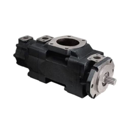
With the codes written down, each remaining step answers one question. Work them in order, because a later step assumes the earlier one came out clean.
Step 2: Compare the port with its own rating, not the pump’s headline
This is the step that decides most cases, and it’s the step the generic sheets can’t do. The triple vane pump pressure ratings below come from four builds in three catalogues, each position rated on its own code.
| Build | P1 shaft end | P2 middle | P3 cover end | Lowest-rated port |
|---|---|---|---|---|
| Vickers 2520VQSV10, 25VQ code 17 / 20VQ code 14 / V10 ring 3 | 210 bar | 210 bar | 172 bar | cover end |
| Vickers 2520VQSV10, 25VQ code 17 / 20VQ code 11 / V10 ring 3 | 210 bar | 140 bar | 172 bar | middle |
| Parker T67EDC, E 045 / D 045 / C 005 | 240 bar | 250 bar | 275 bar | shaft end |
| Tokyo Keiki SQP211-21-6-4 | 17.5 MPa | 14 MPa | 14 MPa | middle and cover |
The Vickers figures come from the pressure tables for the VQ sections and the V10 cover (Eaton 353, pp. 13 and 69). Codes 12 to 17 of the 25VQ series are rated 210 bar, and codes 12 to 14 of the 20VQ series are also 210 bar. Code 11 of the 20VQ falls to 140 bar, and the V10 ring 3 cover is 172 bar.
The first two rows are the same pump family with one centre code changed. The answer moves from the cover end to the middle. That single comparison is why “the cover section is always the weak one” is a habit and not a rule.
Parker prints its cartridge ceilings on p. 4 of the T7 and T67 catalogue, a distributor-hosted copy of HY29-0001/UK: “E: up to 240 bar max.” and “C: up to 275 bar max.” The D cartridge is listed at 280 bar, with a parenthetical 250 bar for multiple pumps, which is where the P2 figure comes from. Tokyo Keiki’s table on B3-2 gives the shaft end 17.5 MPa for every code, the middle 14 MPa for codes 2 to 6, and the cover 14 MPa for codes 2 to 4.
Two qualifications belong with the table.
First, the triple performance table beats the cartridge table. Parker’s p. 67 triple table prints every P2 code at 250 bar, including B codes that p. 4 rates at 300 bar inside a multiple pump. Treat 250 bar as the figure published for that position, and confirm with the manufacturer before running a B section to 300 bar in the middle.
Second, fluid chemistry re-rates the whole pump. Tokyo Keiki states: “Max. working pressure is 14 MPa for phosphate-ester fluid” (B3-2). On a phosphate-ester machine, every SQP section is a 14 MPa section regardless of code.
Then there is the relief arrangement. Eaton gives the flow-control case on p. 12: the primary circuit “is protected by an integral relief valve, but an external relief valve must be provided for the secondary and any additional circuit.” On that build, P1 and P2 depend on valves outside the pump.
The Vickers vane pump troubleshooting chart notes the same point with the parenthetical “(Models with integral relief valve only)” beside “Relief valve stuck open” (p. 10 to 11). If your build has no integral relief on a section, that section’s relief is a separate component to test. The Vickers triple pump page covers which covers carry one.
Step 3: Decide whether the reading is low at all
This is where most condemned cartridges are lost. The catalogue prints flow at stated pressures for specific codes, and the loss between zero pressure and rated pressure is not the same at every port.
Take the Parker T67EDC with an E 045 at P1, a D 045 at P2 and a C 005 at P3. On p. 67, the 045 shaft-end cartridge delivers 213.6 L/min at zero pressure and 196.5 L/min at 240 bar. That is 92.0% retention.
The same digits in P2 are from a different cartridge. As a D 045, it delivers 218.6 L/min at zero and 202.6 L/min at 250 bar, which is 92.7%.
The C 005 cover section delivers 25.8 L/min at zero and 16.1 L/min at 275 bar. That is 62.4%. The cover section loses 37.6% of its delivery at its own rating, while the other two lose under 8%.
A tester who applies one pass mark across all three ports will condemn the only section that is behaving exactly as printed.
Parker goes further and refuses to print a number at all for the smallest cover cartridge. On the same page: “We do not recommend using the size 003 in P3 at 275 bar & 1500 RPM as the internal leakage is over 50% of theoretical flow” (sic). The 003 is 10.8 ml/rev, which is 16.2 L/min theoretical at 1,500 min⁻¹ and matches the printed zero-pressure figure.
At 140 bar, the table prints 11.2 L/min, or 69.1%. At 275 bar, it prints an asterisk.
A 003 cover section delivering under 8.1 L/min at full pressure is not a worn section. It is the documented behaviour of a 10.8 ml/rev cartridge at that pressure.
Tokyo Keiki prints delivery at 1,000 min⁻¹ and 0.7 MPa only, and points to the single-pump curves for the rest. If the catalogue did not print a figure at your pressure, the acceptance number has to come from a commissioning baseline or a curve, not from a guess. The Parker Denison T67 triples page has the full performance tables if you need to read them in context.
The rule that comes out of this step: never condemn a section against a number the catalogue did not print.
Step 4: Separate the pump from the circuit
Cap the outlet, put a gauge and a flow meter at the pump, and load the section against its own relief. Vickers states the standard: “If a test stand is available, the pump should be tested at the recommended speeds and pressures shown in the application catalog” (service information, p. 14).
Then read the two demand-side causes that HOF lists on p. 29. Under III-1-4: “Check if the flow required is not over the available flow and therefore cannot build-up pressure.” Under III-1-3: “Check if the main relief valve is not set at an extremely low pressure and therefore bringing all the flow back to the tank.”
The fork is clean. If the section holds its rating at the pump, the problem is downstream. If it still falls short, the problem is inside.
A composite scenario, built from the numbers above: Priya runs an injection machine with clamp on P1, core pull on P2, and hold on P3. The clamp gauge reads 190 bar cold and 186 bar hot against a 240 bar ceiling. That’s a real shortfall.
But the pump is a Vickers triple with a flow-control cover, so P1 has no integral relief. The first suspect is the external relief on the clamp circuit, not the cartridge. A gauge teed in at the pump settles it in ten minutes.
Step 5: Test the boundary between sections
Load one outlet and hold the other two at low pressure. Watch for pressure or flow where it should not be. On most builds, the cover clamps all three stacks, so a sealing fault at the boundary shows up as an interaction rather than as a single weak port.
The HOF troubleshooting booklet documents two mechanisms that matter here. II-1-6 on p. 8: “Loose pump screws (after modifying the pump, the screws were not tightened to the proper torque and worked loose).” The listed consequence, on p. 12, is “Broken screws”.
The second is II-1-4: “With any cartridge modifications, caution must be taken to check that the rotor/vanes can rotate freely. Vanes can potentially tilt and, in this case, would be squeezed in between the port plates.”
Torque matters because the cover is what holds the stacks together. Vickers prints the figures: “Screw Torque to 35-45 lb.ft. (V10) 75-85 lb.ft. (V20)” (p. 13).
A composite example: Kenji is commissioning a Tokyo Keiki SQP211-21-6-4 and finds the third outlet at 140 bar, which looks 35 bar short next to the shaft-end section. It isn’t short. The cover code is 4, and that section’s ceiling is 14 MPa, so the reading is 100% of its rating.
The full per-code table is on the Tokyo Keiki SQP triples page.
If a fault survives this test, the summary of the six checks lists the mimics that live in the cover and the housing.
Step 6: Read the wear pattern per section
Once a section is open, the wear pattern narrows the cause faster than any gauge reading.
| What you see | What it points to |
|---|---|
| Vane tip wear, even around the rotor | Normal service life at that section’s duty |
| Cam ring scuffing on one section only | Local overheating or a starvation event at that inlet |
| Support plate not flat, or fretted against the ring | Cover screws below torque, or a plate that never seated |
| A scratch running from inlet to pressure area | A vane that was destabilised, not a worn ring |
| Washboarding across all three sections | System-level contamination or aeration, not three failures |
HOF is specific about the scratch. II-1-7 on p. 8: “Even a small scratch between the inlet & the pressure area can destabilize the vane” (sic). The listed consequences are vane marks, noise, limited pressure, and unconstant flow.
The fork at the end of this step is the one that changes the repair. One worn section is that section’s history. Three worn sections are the system’s history: contamination, heat, or suction. Replacing three cartridges without fixing the cause buys the same vane pump failure again.
Before you open a triple pump
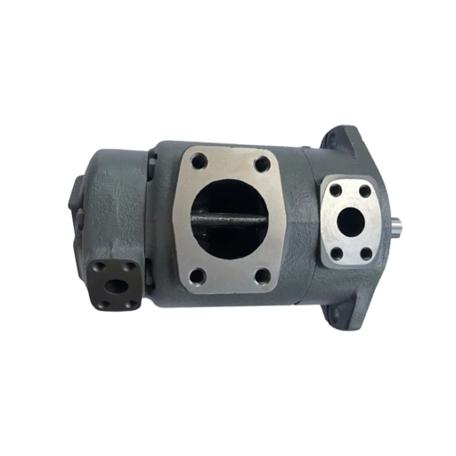
The safety warning is quoted rather than paraphrased, because three outlets mean three places pressure can be trapped. Vickers: “Before breaking the circuit connection, make sure power is OFF, and system pressure is released. Lower all vertical cylinders, discharge accumulators, and block any load that could generate pressure” (service information, p. 12).
Isolate each section’s circuit separately. A triple can hold pressure on one outlet while another reads zero, and the gauge you checked is only one of three.
Then record each section’s parts as they come out, cartridge by cartridge. Before the cover comes off:
- Isolate each circuit on its own, because a triple can hold pressure on one outlet while another reads zero.
- Tag every cartridge with its position and code, in the order the model code gives you.
- Keep the parts for P1, P2, and P3 in separate trays so the stacks cannot be mixed.
That record is what lets the pump go back together with the right cartridge in the right position, which is the failure mode Vickers warns about on the same page.
FAQ: triple vane pump troubleshooting questions
How do I know which of the three sections failed?
Map the function to the port using the model code, read that port’s rating, and compare the reading with the catalogue figure for that code at that pressure. If it holds at the pump, the fault is downstream.
Is the cover-end section always the weakest?
No. On a Vickers 2520VQSV10 with 20VQ code 14, the cover is lowest at 172 bar. Change the centre to code 11, and the middle becomes the lowest at 140 bar. On a Parker T67EDC, the shaft-end E section is lowest at 240 bar.
My third port only reaches 140 bar. Is it worn?
Only if its code rates higher. A Tokyo Keiki SQP211 cover code 4 is rated 14 MPa, so 140 bar is full rating. Check the cover code on B3-2 before condemning anything.
Can pressure move from one outlet to another?
Yes, and it is a boundary fault rather than a cartridge fault. Load one section and watch the other two. A rise where there should be none points to the cover, the screws, or a plate that is not seated.
How do I test a section without a test stand?
Cap the outlet at the pump, fit a gauge and a flow meter, and load against that section’s own relief. Test at the speed and pressure the catalogue lists for the unit. If the section holds there, the fault is in the circuit.
Conclusion
Triple vane pump troubleshooting is a reading exercise before it is a repair job. Write down the three codes, find each port’s own ceiling, and compare the gauge with the figure the catalogue printed for that code at that pressure.
The three habits that decide the outcome are simple. Read the code before the gauge. Compare each port with its own rating rather than the pump’s headline. And treat a low reading at a small cover section as normal until the retention figure says otherwise.
If the section genuinely is worn, the replacement is a cartridge, not a pump. Cartridge kits for each section are matched by code, and the code is what you already wrote down at step one. Triple vane pump troubleshooting ends with that code in hand: send the three codes and the readings from each port, and the numbers on this page can be checked against your build before anything comes off the machine.