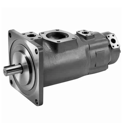
Triple vane pump shaft power is the sum of the three sections’ input power, each read at its own operating pressure. The shaft carrying that sum is limited by torque rather than by kilowatts, and a torque limit converts to a smaller power ceiling as drive speed falls. So the motor and the shaft get checked against two different numbers.
The arithmetic isn’t the hard part. Which pressure you add at is.
Most sizing guides walk you through flow, pressure, and a division by efficiency, and the answer looks complete. On a three-section pump, it describes one section, or a pump that doesn’t exist. A triple vane pump is three rotary vane cartridge sections on one shaft, not the three-plunger reciprocating pump a search for “triplex” will also return.
If the cartridge arrangement is new to you, how a triple vane pump is built covers the stacking order. Here is what the catalogues print, what the combined shaft power comes to on a real build, and how to keep the motor frame and the shaft limit from contradicting each other.
If three circuits are already allocated to three positions, the drive can be checked against a catalogue build. Send the three flows and pressures, and the numbers below can be run on your codes.
Key Takeaways
- On a Parker T7DCB build of B28, 014, and B10 at 140 bar, the sections draw 32.7, 17.6, and 11.7 kW, which is 62.0 kW at the shaft against 20.7 kW if you average them.
- The catalogue’s input-power column is already measured at the shaft, so 62.0 kW takes a 1.15 service factor and lands on a 75 kW frame; dividing by 0.85 first counts the same loss twice.
- The same shaft carries 108.1 kW at 1,500 rpm and 43.2 kW at 600 rpm, because its 43,240 Vi x p limit is 688.2 N m and a power ceiling is torque times speed.
- Whether the sections ever load together decides the frame, from 45 kW for the largest one to 75 kW for all three, and holding the same flows at 900 rpm pushes the shaft from 54.3% of its limit to 89.0%.
- Loaded to their tabulated port ceilings instead of to duty, the same three sections draw 117.6 kW and reach 103.4% of the shaft limit, so the build is legal at duty and illegal at its ceilings.
Triple vane pump shaft power: read each section at its own pressure, then add
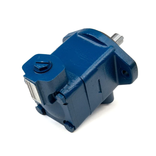
The rule is printed, and the word doing the work is “own”.
Eaton states it for thru-drive pumps: “To determine the total input power for thru-drive pumps, add the kilowatts for the front pump and the rear pump together, at the selected operating pressures” (Eaton 5035.00/EN/1097/A, p. 11). That brochure documents thru-drive, double, and integrated motor pumps, and contains no three-section pump, so the sentence is applied to triples by extension rather than quoted for them.
Parker states the same principle for losses: “Total hydromechanical power loss is the sum of each section loss under its respective operating conditions” (catalogue HY29-0001/UK, p. 54). A distributor hosts that copy; ask Parker Hannifin for the current revision.
Each section’s own pressure is the whole content of the rule. One circuit may run at 250 bar and another at 60, and the pump doesn’t blend them.
Where those three duties come from is a separate decision, covered in allocating three circuits to three sections. This page starts once the pressures are set.
What the sum looks like on one build
Take a T7DCB with a B28 shaft-end section, an 014 middle section, and a B10 cover-end section, all at 140 bar on a 1,500 rpm drive. Every figure below is from the performance table on page 53.
| Section | Code and displacement | Flow at 140 bar (L/min) | Input power (kW) | Hydraulic power (kW) |
|---|---|---|---|---|
| P1 shaft end | B28, 90.0 ml/rev | 128.4 | 32.7 | 29.96 |
| P2 middle | 014, 46.0 ml/rev | 64.0 | 17.6 | 14.93 |
| P3 cover end | B10, 31.8 ml/rev | 46.0 | 11.7 | 10.73 |
| Total | 62.0 | 55.63 |
The shaft-end section carries 52.7% of that 62.0 kW, the middle 28.4%, and the cover end 18.9%.
Three wrong answers sit next to that 62.0 kW, and each has a plausible story.
| Wrong answer | How it is produced | Result (kW) | Why it is wrong |
|---|---|---|---|
| Average of the three | Each section checked, nobody adds | 20.7 | Describes one section, not the pump |
| Largest section x 3 | Cautious engineer assumes three alike | 98.1 | The sections are not alike |
| Hydraulic sum ÷ 0.85 | Efficiency applied on top of the catalogue | 65.4 | Counts the same loss twice |
Two routes to one shaft, and the mistake of taking both
The catalogue’s input-power column is measured at the pump shaft. Route one reads it and adds. Route two computes flow times pressure, divides by overall efficiency, and arrives at the other end. Vane pump input power arrived at either way is still the same physical quantity, which is why the two routes should agree.
| Route one | Route two | |
|---|---|---|
| Starting point | The catalogue’s input-power column | Each section’s flow and pressure |
| Work | Read the figure, add the three | Q x p ÷ 600 per section, total ÷ efficiency |
| Result on this build | 62.0 kW | 55.63 ÷ 0.85 = 65.4 kW |
| Sources of error | None, if the pressure is right | The assumed efficiency |
| Use it when | The catalogue prints a column | It doesn’t |
On this build route, two gives 65.4 kW against route one’s 62.0 kW, a 5.5% gap created by the assumed efficiency. Apply a 1.15 service factor to the 65.4, and you get 75.3 kW, still a 75 kW frame, so the error hides. It hides for one motor size and turns up on the next.
Route two is the fallback when a catalogue has no input column. It isn’t a cross-check to run on top of route one.
The site’s own vane pump sizing guide uses route two with an overall efficiency it puts near 85% and a service factor of 1.15 to 1.20. It starts from flow and pressure rather than from a table. Both routes are valid. Running them together isn’t.
The motor takes the sum, and the service factor is not for the pump
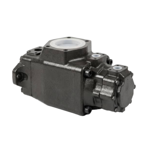
A 62.0 kW duty with a 1.15 service factor is 71.3 kW, which selects a 75 kW frame. A four-pole motor at 1,475 rpm develops 9554 x 75 ÷ 1475 = 485.8 N m rated, or 558.7 N m at the service factor. The duty torque of 394.9 N m sits at 81.3% of rated and 70.7% of the service-factor figure.
Both are comfortable, and neither is a margin against a missing section.
The service factor is a motor convention, not a pump requirement. None of the three catalogues here prints one for the pump. It covers coupling losses, voltage variation, and thermal ageing.
What it doesn’t cover is a section you forgot to add, or a port set above its ceiling. A 10% pressure error at constant flow is a 10% power error, and a 15% service factor absorbs it without a symptom.
Field note: Henrik, a commissioning engineer with a machine builder in Scandinavia, ordered a 90 kW motor for a build whose three sections summed to 62 kW. The motor was never the problem; the coupling key sheared on the third start because the cover section sat 60 bar above its port ceiling. The sum sizes the motor, and the torque limit sizes the shaft. They are two separate checks.
A shaft limit in newton-metres is a power limit that moves with speed
Three catalogues print the same physical limit three different ways, and all three convert to one kind of number.
| Source | Printed form | Limit | In N m |
|---|---|---|---|
| Parker HY29-0001/UK, T7DCB, p. 52 | Vi x p, column headed P1 + P2 + P3, shaft 1 | 43,240 | 688.2 |
| Parker HY29-0001/UK, T67EDC, p. 66 | Vi x p, shaft 1 | 114,600 | 1,823.9 |
| Eaton Design Guide 353, p. 48, No. 297 shaft | N m | 1,017 | 1,017 |
| Tokyo Keiki B3, p. 3-3, SQP432 | N m | 950 | 950 |
The Parker figure converts with T = Vi x p ÷ 20π. Its shaft-1 limit of 43,240 is 688.2 N m.
A torque limit is fixed. The power it allows isn’t, because power is torque times speed. Multiplying the 688.2 N m by the angular speed at each drive speed gives the table below, which is the shaft torque limit restated as a kilowatt ceiling. The 9,554 constant used further down is the same conversion rounded, so a hand calculation can land a tenth of a kilowatt away.
| Drive speed (rpm) | kW the shaft can carry |
|---|---|
| 600 | 43.2 |
| 750 | 54.1 |
| 900 | 64.9 |
| 1,050 | 75.7 |
| 1,200 | 86.5 |
| 1,500 | 108.1 |
| 1,800 | 129.7 |
| 2,200 | 158.5 |
One pump, one shaft, and a power ceiling that moves by a factor of nearly four across the catalogue’s own speed window. The same conversion, read against three other printed limits at 1,500 rpm:
| Source | Printed limit | kW it carries at 1,500 rpm |
|---|---|---|
| Eaton 2520VQSV10, Design Guide p. 48 | 344 N m | 54.0 |
| Eaton 45**VQSV10, Design Guide p. 48 | 1,017 N m | 159.7 |
| Tokyo Keiki SQP432, B3 p. 3-3 | 950 N m | 149.2 |
Tokyo Keiki’s worked case shows why speed decides. An SQP432-60-38-14 at 1,200 rpm draws 57.1 + 36.2 + 18.4 = 111.7 kW at its three sections’ stated loads. That gives 9554 x 111.7 ÷ 1200 = 889.3 N m, against a 950 N m limit.
That’s 93.6% of the limit. The same 111.7 kW at 1,000 rpm would be 1,067.2 N m, or 112.3% of it. Their example clears because of the speed it’s quoted at, not because of the pump.
To learn more information, please read our article on Vickers triple vane pumps and Denison triple vane pumps.
Three loading cases, three different motors
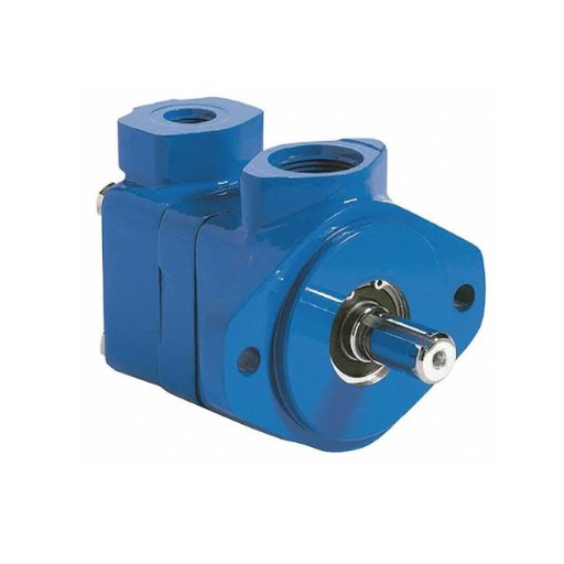
Eaton prints two versions of the summing rule, one page apart, and the difference between them is the whole of this section.
The first: “The input kilowatts should not exceed 16 kW with only one pumping unit in operation, or with two pumping units in operation simultaneously.”
The second: “If the shaft end and cover end pumps will not be loaded simultaneously, find the maximum sum of the two power requirements, considering their load cycles separately” (Eaton 5035.00/EN/1097/A, pp. 11 and 12).
On a triple, that gives three cases rather than two. The loading case that governs triple vane pump motor sizing is whichever of the three actually happens on the machine.
| Case | Sections loaded | Sum (kW) | With 1.15 | Frame |
|---|---|---|---|---|
| All three together | P1 + P2 + P3 | 62.0 | 71.3 | 75 kW |
| Largest two only | P1 + P2 | 50.3 | 57.8 | 75 kW |
| Largest one only | P1 | 32.7 | 37.6 | 45 kW |
The spread runs from 45 kW to 75 kW, which is 40% of the frame. A 55 kW motor would not serve the two-section case, because 55 ÷ 1.15 = 47.8 kW is short of 50.3. A 37 kW motor would not serve the single-section case, because 37 ÷ 1.15 = 32.2 kW is short of 32.7.
Which case sizes the motor is a question about the machine cycle, not the pump. The motor has to survive the worst combination that actually occurs. The shaft has to survive the worst combination that can occur at one instant, which is the full sum whenever the control logic permits it.
That distinction is worth writing down before the pump is ordered, because it isn’t recoverable afterwards. Eaton’s design guide puts the warning plainly: “Never assume pumps in a double, triple or thru-drive pump assembly can be simultaneously loaded to rated pressure. Shaft loading must be checked for excessive torque and side loads” (Design Guide 353, p. 7).
The same build makes the point numerically. Load each port to its tabulated ceiling, B28 at 250 bar, 014 at 275 bar, and B10 at 300 bar, and the input power sums to 117.6 kW. Vi x p reaches 44,690, which is 103.4% of the 43,240 limit. The build is legal at duty and illegal at its own ceilings.
That doesn’t mean triple pumps carry a blanket derating: none of the three catalogues publishes such a coefficient, and the port ceilings in the table already are the multi-unit figures.
Field note: Nurul, a plant engineer in Johor, ran a clamp, eject, and hold cycle where the three sections never overlapped. Documenting the loading cases took the motor from a 75 kW frame to 45 kW. She spent part of the difference on a six-pole motor, so the same power arrived at 980 rpm with 731.2 N m of rated torque instead of 485.8. The loading case is a machine-cycle decision, and it’s worth more money than the pump.
What triple vane pump shaft power costs when the drive runs slow
Start with the part that trips people up: at fixed displacement and fixed pressure, triple vane pump torque doesn’t change with speed at all. A 90 ml/rev section at 140 bar gives 90 x 140 ÷ 20π = 200.5 N m whether it turns at 600 rpm or 1,800 rpm. Input power falls with speed. Torque does not.
So the penalty isn’t in the torque curve. It’s in holding the flow.
Drop from 1,500 to 900 rpm and a fixed-displacement pump delivers 60% of the flow. To keep the three circuits supplied, every displacement has to grow by about two-thirds, and Vi x p grows with it.
| Speed (rpm) | Codes | Delivered (L/min) | Vi x p (% of 43,240) | Torque (% of 688.2 N m) |
|---|---|---|---|---|
| 1,500 | B28 / 014 / B10 | 128.4 / 64.0 / 46.0 | 23,492 (54.3%) | 394.9 N m (57.4%) |
| 1,200 | B35 / 017 / B12 | 129.5 / 65.0 / 47.5 | 29,778 (68.9%) | 501.1 N m (72.8%) |
| 1,050 | B38 / 020 / B15 | 120.0 / 62.0 / 50.8 | 32,816 (75.9%) | 551.1 N m (80.1%) |
| 900 | 045 / 025 / B15 | 121.7 / 66.4 / 43.3 | 38,500 (89.0%) | 639.0 N m (92.9%) |
Same flows, same pressures, same three circuits. The shaft goes from 54.3% loaded to 89.0%, and the torque from 57.4% to 92.9%. The Vi x p figures are exact, because they come from the catalogue’s displacements. The torque column assumes the 89.7% overall efficiency measured on the original build, so treat it as approximate.
There’s a floor, and it isn’t where most people expect. Section by section, the smallest code in each position’s list that still holds its duty at 140 bar:
| Section | Code | Duty (L/min) | Lowest speed that delivers it |
|---|---|---|---|
| P1 shaft end | 045, 145.7 ml/rev | 120 | 888 rpm |
| P2 middle | 025, 79.3 ml/rev | 60 | 820 rpm |
| P3 cover end | B15, 50.0 ml/rev | 42 | 874 rpm |
The binding constraint is the shaft-end section at 888 rpm, not the cover. Below that, no code in the P1 list reaches 120 L/min.
Choosing 050 instead of 045 buys a lower floor of 818 rpm and pushes Vi x p to 40,222, or 93.0% of the limit. That trade sits in one row of a table, which is the useful part. Below 818 rpm, the family runs out, and the answer is a larger pump or a different section count, not a larger motor.
The catalogues agree about operating there. Eaton warns that pumps “should not be operated at or near rated pressures at idle speeds for extended periods” (Design Guide 353 page 7). Parker caps any run over 50% internal leakage at five seconds (catalogue HY29-0001/UK page 54). For a deep look, see our guide to Tokimec SQP triple vane pumps.
If the drive speed is fixed by the machine and the numbers don’t close, the double vane pump configuration guide covers the same flow shared across two sections instead of three.
Derate the pressure first, then add the kilowatts
The order of operations doesn’t match the order in most sizing templates.
| Step | What you read or compute | What it protects |
|---|---|---|
| 1 | That port’s ceiling, from its own column, at your fluid class and duty | The pressure rating, before any power figure means anything |
| 2 | Any time-weighted average the duty cycle calls for, per port | The duty, not the peak, where the peak is brief |
| 3 | Each section’s flow at its own pressure, into hydraulic power | The sum itself |
| 4 | The three sections, added | The motor frame |
| 5 | The service factor, once, on that sum | The motor’s thermal margin |
| 6 | Torque at the chosen speed, against the shaft’s printed limit | The shaft |
Steps 1 to 4 belong to the pressure side, where the vane pump derating guide covers the factors. Steps 5 and 6 belong here.
Eaton adds two footnotes to its power charts that matter for step 3, and both cut against the intuition that a light load is a safe load. “As operating pressure reduces to minimum, flow increases from chart values by approximately 4 to 5% for piston pumps and 10 to 12% for vane pumps.”
The second reads: “As the motor pump reaches full load, the motor speed droop will reduce output flow from chart values by approximately 2%.”
A section running at low pressure doesn’t unload the motor as much as its pressure suggests, because a vane pump’s flow rises as pressure falls. The power sum at part load is therefore a little higher than flow times pressure read from the chart.
Field note: Callum, a maintenance lead at a press builder in Scotland, sized a build at the series headline pressure instead of each port’s multi-unit figure. Every section’s power was about 10% high on paper. The 1.15 service factor absorbed it, and the press ran for 14 months.
It failed when a port was re-piped and the two highest-power sections began overlapping. The service factor hid the error; it did not remove it.
FAQ
How do I calculate shaft power for a triple vane pump?
Add the three sections’ input power, each at its own operating pressure. If the catalogue prints an input-power column, read it directly, because it’s already measured at the shaft. If it doesn’t, compute flow times pressure divided by 600 for each section, then divide the total by overall efficiency.
Does a three-section pump need a bigger motor than three separate pumps?
It needs the same power and a different check. Three separate pumps each take their own shaft, so no single shaft carries a torque sum. One triple carries all three loads on one shaft, which is why the shaft limit and the loading case become selection constraints rather than footnotes.
Why does the shaft limit matter more at low speed?
The limit is a torque, and the power a torque represents falls with speed. A shaft rated for 688.2 N m carries 108.1 kW at 1,500 rpm and 43.2 kW at 600 rpm. Running slower also forces a larger displacement to hold the same flow, which raises the torque demand at the same time.
What is the difference between a triplex pump and a triple vane pump?
A triplex pump is a reciprocating plunger pump with three plungers, and its flow pulses. A triple vane pump is one body with three rotary vane sections on a common shaft, with steady flow and the torque sum landing on that one shaft.
Can I use the service factor to cover a pressure mistake?
No. A 15% service factor absorbs a coupling loss or a voltage dip. A port set one step above its ceiling can add 20% or more to that section’s power, and the motor will run hot without a visible symptom until the insulation fails.
Sizing the drive is two decisions, not one
Triple vane pump shaft power and shaft torque are two separate answers to the same three sections. The sum sizes the motor. The torque limit sizes the shaft. Both use the same pressures and the same catalogue rows, and neither substitutes for the other.
- Read each section at its own pressure, and use the catalogue’s input column where it exists rather than dividing hydraulic power by an assumed efficiency.
- Apply the service factor once, to the sum, and never on top of an efficiency divisor.
- Convert the shaft’s printed limit into a power ceiling at your chosen speed before comparing it with the duty.
- Decide which loading case governs the motor and which governs the shaft, and write both down before the order goes out.
- If the speed has to fall, price the displacement increase, because that’s where the shaft limit tightens.
If you have three duties and a speed, send them over, and the three checks can be run on your codes before anything is ordered.
Ready to check a build against its frame and shaft limits? LOYAL INDUSTRIAL PTE. LTD. supplies hydraulic pumps, motors, valves, and replacement components across brands. Send the three duties and the drive speed, and ask for the triple vane pump shaft power and torque figures for the specific model.