Hydraulic system flushing after pump failure should follow an approved circuit plan, remove contamination from affected volumes, and finish against written acceptance criteria. Start by tracing the failure path; keep component condition, cleaning coverage, and fluid test results as separate release decisions.
A replacement pump can be ready before its circuit is ready. Which connected parts still need work? That is often the hard question.
A clear workpack links each decision to its proof. That may be a drawing, inspection, or sample report.
This guide helps you build that record. It does not prescribe one pressure or run time for every job.
Illustrative scenario: A workshop has a replacement pump beside the machine. The reservoir has been cleaned, but a remote branch has no treatment record. The open question is whether that branch was assessed and reached. A clean tank alone cannot answer it.
Key Takeaways
- Map the affected flow paths before choosing flushing equipment or reconnecting parts.
- Record whether each retained component needs cleaning, inspection, repair, or replacement.
- Match every sample result to the volume and conditions it represents.
- Close the component, loop, and sampling records before handing the machine to the startup team.
Before approving the workpack, review our guide to ISO 4406 cleanliness targets. Use the equipment requirements to select acceptance criteria; the code describes particle contamination, while the recovery also needs condition and coverage evidence.
Set the recovery boundaries before ordering the flush
Record what failed and what remains unknown
Identify the machine, failed pump, and drawing revision. Keep the inspection findings and note where debris was found. Distinguish a confirmed internal breakup from an external leak or an unexplained performance loss. These findings lead to different cleanup questions.
Keep gaps in the diagnosis visible.
Avoid identifying a failed material or component from debris color alone. Record the observation and ask for qualified examination where it affects the repair decision. Also separate the initial cause from damage that may have followed it. Cleaning will not fix a source that keeps adding dirt.
Trace the connected volumes
Mark the paths that could connect the failed unit to the reservoir, valves, cooler, actuators, and auxiliary circuits. Include case drains and pilot lines where the drawing shows them. Trace the actual connections and valve states rather than assuming every branch received the same flow.
Reservoir draining leaves the question of fluid held elsewhere. Quaker Houghton’s hydraulic-system flushing guide discusses retained contamination, cleaning and recharge. Apply that principle to the machine drawing: a closed or isolated path needs its own treatment decision.
For the opening scenario, the remote branch belongs on this marked drawing. Its status stays open until someone establishes its exposure and approved treatment. This defines a gap in the record. It does not prove the branch is dirty just because it is remote.
Create a short job charter
Use a cover sheet with machine ID, pump identity, drawing revision, suspected contamination, affected volumes, and responsible reviewer. Add the source documents, acceptance basis, and unresolved questions. Keep findings apart from proposed actions. The next shift needs to know what is confirmed.
Choose tests for the actual concern. A particle count cannot tell you everything about water or the oil type. If water ingress is suspected, the related guide to water in hydraulic oil explains that separate investigation. Record the suspected entry path and how its repair will be checked before closing the recovery.
Decide what to clean, inspect, repair, or replace
Give each component a disposition
Build a component register from the affected circuit. Give each item an identifier that matches the drawing. Record the concern, approved treatment, required evidence, decision owner, and release status.
A note saying cleaned needs more detail. Name the method and record what was checked afterward.
| Item or volume | Decision to resolve | Evidence to attach |
|---|---|---|
| Reservoir and housings | Access, cleaning method, and condition | Inspection record and cleaning report |
| Filter housings and elements | Service method and correct replacement | Hardware identity and service record |
| Lines and remote branches | Exposure and treatment coverage | Marked loop drawing and run log |
| Cooler, motor or actuator | Cleanability and retained condition | Applicable procedure and assessment |
| Sensitive valves | Protection and separate treatment | Isolation plan and component decision |
Use these rows as a planning template. They do not approve reuse of any part. Fill them from the equipment instructions.
If you cannot reach the dirt or assess the damage, keep the part on hold. Ask the engineer or service specialist to review it.
Each row also needs a record ID, date, and reviewer. Keep the rejected option and reason when that choice affects the repair scope.
Separate fluid cleanliness from mechanical condition
A clean oil sample does not prove a damaged part is fit for use. Check the part too. A repaired part does not prove its lines are clean either. Keep the inspection decision separate from the flushing result, then bring both into the final release review.
Illustrative scenario: A team records a clean reservoir but has no assessment for the cooler. The useful next step is to obtain its inspection and cleaning requirements. The tank result alone cannot tell them to reuse or replace it. The cooler row remains open until the approved decision has supporting evidence.
Control contamination during the work
Plan clean storage and handling for disconnected parts, hoses, and fill equipment. Record how to protect openings and add new fluid to the clean circuit. Dirt can enter a clean part during filling or reconnection.
Include seals, access covers, and breathing arrangements in the recurrence review. The guide to reservoir breather inspection supports that specific subtask. Breather service helps address an entry route; it does not remove debris already retained in an untreated circuit. Record both jobs separately so one completed action cannot hide the other.
Specify a hydraulic system flushing workpack for each loop
Define the temporary circuit
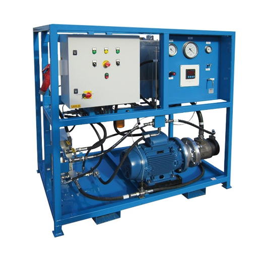
For every loop, show where fluid enters, which path it follows, where filtration occurs, and where it returns. List the parts removed, isolated, or treated on their own. Draw temporary hoses and connections explicitly, including the sampling points and pressure protection required by the approved arrangement.
HAWE’s flushing guidance describes low-pressure flushing, careful filter monitoring, and protection of sensitive devices. It recommends considering a separate flushing power pack because the working pump would otherwise face contamination. This is a design principle for the reviewed arrangement, not permission to connect any available pump.
Ask the responsible technician to confirm how sensitive valves and other protected devices will be handled. Check the exceptions for each part. A bypass path that cleans supply and return lines may leave an actuator outside that path. Keep its separate treatment in the component register.
Confirm fluid and equipment compatibility
Specify the approved fluid and its compatibility with retained oil, seals, hoses, filter media, and component requirements. If you plan to use a separate flushing fluid, record how to remove it. Specify the final fill, too. Do not substitute diesel, solvent, or an improvised blend because it appears in an online discussion.
Choose the rig for the approved job. Record required flow, fluid condition and temperature range, pressure limits, filtration performance, and dirt capacity. Take the settings from the correct procedure.
Flow and oil properties affect cleaning. Stay within the limits of every connected part.
High pressure alone is not a measure of cleaning coverage. A pressure test does not measure how much dirt was removed. If both tasks are needed, keep their approvals, limits, and results separate. This keeps a passed pressure test from being used as the sole proof of cleaning.
Use a loop register that can be audited
| Workpack field | Entry required before the run |
|---|---|
| Loop ID and drawing | Exact path, revision, and connected volumes |
| Protected items | Isolation method and separate treatment reference |
| Fluid and equipment | Approved fluid, rig, hoses and filter identity |
| Operating limits | Approved flow, temperature, and pressure protection |
| Monitoring | Readings, frequency, stop conditions and responsible person |
| Sampling | Point, method, conditions and acceptance reference |
| Restoration | Temporary items to remove and connections to restore |
In the opening example, the remote branch needs an entry showing its actual path or explaining why it is treated separately. Copying the reservoir loop’s completed status into that row would not establish coverage. The register should expose a missing path before the run starts.
Keep the approved drawing beside the rig. When a connection changes, stop and review its effect on loop coverage. Log the revision before work resumes.
When choosing equipment, compare filter carts and kidney loops against the reviewed loop duty. Reservoir filtration can support cleanup, but it cannot establish that an isolated branch received treatment. Keep equipment selection tied to the circuit question it must answer.
Monitor progress and investigate a stalled or returning count
Keep a run log alongside the sample log
Record loop identity, fluid temperature, relevant flow and pressure readings, filter indications, interruptions, and element changes. Use the monitoring method and limits for the actual hardware. The operator needs clear instructions for a blocked filter, bypass indication, leak, or unexpected machine behavior.
Terex Tech Tip 196 explains filter checks for its equipment. It warns that cold oil can affect bypass in that setup. In the described Terex return-filter arrangement, the change indication is 20 psi, and bypass occurs at 25 psi.
Those values belong to that hardware; they are not settings for other machines. Check the actual filter instructions and log the readings.
See Terex Tech Tip 196, page 4.
Don’t just run longer when the count stops falling. First check whether the new result can be compared with the last. A new sample point may tell a different story. The report can use the same code format and still describe a different volume.
Use a plateau or rebound decision path
Start with the sample ID and test conditions. If they changed, resolve the comparison before assigning a cause. If they match, review filter condition, bypass status, and the recorded flow path. Then check for missed volumes, contamination introduced during handling, or a component that may still be generating debris.
Each possible cause needs proof. A returning count does not identify a cooler, valve, or pump as the cause by itself. Add the inspection or test needed to distinguish the possibilities, and keep the affected release decision open.
Ask for a review of parts whose condition is still unclear. Do not keep cycling with no end in sight.
Illustrative scenario: A tank sample improves, while a later branch sample raises concern. The samples represent different locations. The team first checks which volumes each point represents, then reviews the branch treatment record. This comparison prompts investigation; it does not prove a particular component has failed.
Record the decision after every investigation: continue under the approved plan, service the filter, reassess the loop, or hold for component review. Include the reason and authorizing person. That short entry helps prevent repeated runs with no change in the question being tested.
Verify hydraulic system flushing with representative evidence
Agree the acceptance basis before collecting the final sample
Write down the machine and part requirements. Add the document revision, test method, and person who can approve release. If the requirements conflict or have gaps, ask the technical reviewer to resolve them.
Agree on the code before the test. Do not choose one to suit a result already seen.
The MTS Hydraulic Fluid Care Guide connects fluid analysis, contamination investigation and flushing in its servohydraulic test-system context. Its cleanliness examples show why the equipment scope matters. They do not supply a universal target for every industrial or mobile hydraulic system.
Keep three questions visible: Was the intended volume treated? Does its fluid meet the applicable criteria? Are the retained components acceptable?
A yes to one does not answer the other two. Link each answer to its proof in the closeout record.
Tie every result to a sample register
| Register field | What it establishes |
|---|---|
| Sample ID, date, and time | Traceable identity and sequence |
| Loop and exact sample point | Volume the result is intended to represent |
| Fluid identity and conditions | Context needed to interpret the test |
| Collection method | How the sample was obtained |
| Instrument or laboratory | Source of the reported measurement |
| Applicable criterion and result | Basis for the acceptance decision |
| Exceptions and reviewer | Limits, unresolved questions and ownership |
A supply-container sample can describe the supplied fluid. It cannot establish what happened inside a connected branch after circulation. Likewise, an isolated tank sample cannot automatically represent every actuator or remote return. Choose points through the approved sampling plan and retain the link to the drawing.
In the preceding scenario, the team needs separate, correctly identified records for the tank and branch. The reviewer can then decide what work or tests are still needed. Do not relabel the branch result as a repeat tank sample. That would hide the difference.
Keep particle and fluid-condition decisions separate
Particle counts are useful for the applicable cleanliness question. You may need other tests for water, viscosity, oil type, or oil breakdown. Choose them with the lab and follow the equipment requirements. A visually clear sample cannot replace those tests, and a particle result alone cannot clear an unrelated fluid-condition concern.
Use the approved method for repeat samples. Log any change in test conditions. Keep the original reports, including poor results, for review.
Our guide to representative hydraulic oil sampling expands the collection task. It helps the team compare like with like. The number of release samples comes from the approved plan.
Close the workpack and hand it to recommissioning
Reconcile the records before signing
Bring the component register, loop log, and sample register together. Use this closeout check:
- Match each completed row to an inspection, treatment record, or test report.
- Resolve item IDs and drawing revisions that do not match.
- List each open restriction, its owner, and the action still required.
- Confirm that an empty exception field means reviewed and clear.
Keep the signed review with the workpack. The next shift needs access to the reports, not just a verbal handover.
The closeout should identify the acceptance basis, work performed, final fluid, filter status, and outstanding decisions. Include the person who reviewed each discipline and the authority responsible for release. Record temporary connections and how restoration will be checked against the approved circuit.
Hand over the next controlled activity
Removal of temporary equipment, reconnection, filling, priming, bleeding, and startup follow the applicable OEM procedures. A flushing sign-off does not replace those instructions. It does not prove machine performance.
Tell the startup team what has been restored and which checks are still due. Do this before the machine runs again.
Return to the opening example: the replacement pump is ready, but the remote branch needs evidence. The workpack should show either completed, reviewed treatment or a clear hold point. A purchase receipt cannot close that row. Neither can a clean tank sample.
Before the release meeting, assemble the checklist and review how to interpret an oil analysis report where results need explanation. The practical finish is a traceable decision that another shift can follow, with the limits of the evidence still visible.
Questions to resolve after a hydraulic pump failure
Is draining the reservoir enough after internal pump failure?
Draining alone does not establish that connected lines, components, and retained volumes are clean. Review the actual contamination path, inspect affected parts, and define their treatment. The workpack should distinguish reservoir service from branch coverage, then verify the relevant volumes against the approved acceptance plan before release.
Can the replacement pump be used for the cleanup?
Do not assume the replacement pump should circulate contaminated fluid. HAWE recommends considering a separate flushing power pack to avoid exposing the working pump. The approved arrangement must protect the replacement and sensitive components, with compatible equipment, fluid, and operating limits selected for the particular circuit and contamination concern.
Can a kidney loop prove every branch is clean?
A kidney loop can filter the volume connected to its flow path. That result does not establish treatment of an isolated branch or actuator. Map its connections and identify what the samples represent. Any volume outside the path needs its own documented assessment, treatment decision, and relevant acceptance evidence.
Must the cooler and hoses always be replaced?
There is no universal reuse or replacement decision for every failure. Assess exposure, damage, accessibility, and the applicable cleaning requirements. If condition or cleanliness cannot be established, hold the component for specialist review. Record the approved disposition and evidence instead of assuming either a clean tank or a new pump settles it.
Which cleanliness code should be used for acceptance?
Use the requirements for the actual machine and relevant components, with the sampling method and acceptance authority documented. A code quoted for another manufacturer’s application is not automatically transferable. Also identify any fluid-condition tests or inspections needed, because particle cleanliness does not establish every aspect of recovery readiness.
How long should flushing run before release?
Use the approved plan and test results. There is no single timer setting for all jobs.
Review treatment coverage, filter condition, comparable sample results, and component decisions. If progress stalls or contamination returns, investigate the reason before extending the run. Time spent circulating fluid is a log entry, not proof that the job is complete.