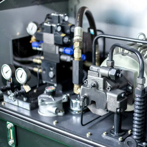
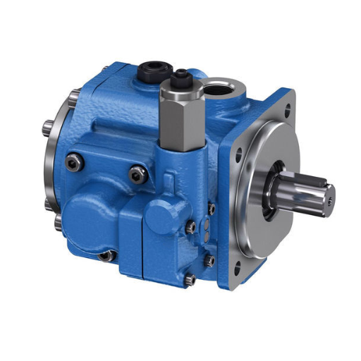
A vane pump on a hydraulic press supplies the flow that builds pressing force, holds it through the dwell, and drives the return stroke. On most large presses, it does not supply the fast approach. A prefill valve fills the main cylinder from a tank, and the pump only pressurises what the tank has already delivered.
That fact decides how you size the pump, and it is the fact most press buyers never see. Catalogues label a vane pump “suitable for press machines” and stop there. The sizing decision then defaults to approach speed, which is the one number the pump does not control.
This guide walks the cycle in order, from workshop press to press brake, and gives the arithmetic that turns tonnage into flow on metal forming equipment. For the full family overview, first start with our complete guide to high-pressure vane pumps.
Key Takeaways
- On a press with a prefill valve, the pump builds tonnage; the gravity tank fills the stroke.
- Press duty is a hold duty. Size on the continuous rating at the real oil temperature.
- Tonnage is ram area multiplied by pressure, so the pump’s pressure class sets the cylinder bore.
- Decompression damages more press pumps than wear does.
- Above roughly 250 to 310 bar continuous, a piston pump is the better press pump.
What a Vane Pump Does on a Hydraulic Press
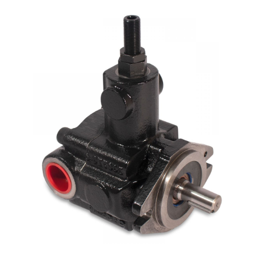
On a hydraulic press, the vane pump converts motor torque into flow, and that flow raises pressure only when the ram meets resistance from the work. The pump supplies pressing, holding, and retraction. On large presses, it does not supply the approach volume, because the cylinder is far too large for any pump on the machine to fill quickly.
| Phase | Flow demand | Pressure demand | What supplies it |
|---|---|---|---|
| Rapid approach | Very high | Low, often 30 to 50 bar | Prefill tank, rapid cylinder, or regeneration |
| Touch and changeover | Falling | Rising | Pump |
| Pressing | Low | High, at the tonnage pressure | Pump |
| Dwell and hold | Near zero | High and sustained | Pump, or an accumulator |
| Decompression | Small and controlled | Falling, controlled | Decompression valve |
| Retraction | High | Low to medium | Pump, with tank exhaust through the prefill valve |
Tonnage pressure is the pressure that, multiplied by the effective ram area, produces the press’s rated force. It is the only pressure in the cycle that should drive pump selection.
A published design shows the shape of these numbers. A Japanese press patent from Nippo Industry runs a vane pump rated at 32 MPa with 28 cc/rev displacement on a servo motor. The machine descends at 3.5 MPa, slows to 20 MPa as it approaches the work, and reaches 29.0 MPa to generate 153.9 tons of pressing force (). The pump spends most of its life at a fraction of its rating.
Two Ways a Press Gets a Fast Approach
Approach speed is set by the circuit, not by the pump alone. There are two common architectures, and telling them apart is the first thing to do before ordering a replacement.
Small-area rapid cylinder or regenerative circuit
The pump drives a small effective area during approach, so modest flow produces high ram speed at low force. A rapid cylinder may be separate from the main ram, or the circuit may return rod-end oil to the cap end so the pump only makes up the rod volume.
The Nippo design uses a dedicated 78.5 cm² chamber for fast descent. A 28 cc/rev pump running near 1,500 rpm delivers about 42 L/min into that area, which works out to roughly 89 mm/s of ram speed. When the ram meets the work, the circuit switches to the larger area and pressure rises. The pump is sized for approach flow here, but only because the approach area is small.
Prefill valve and gravity tank
A four-column drawing press or a large straight-side press may have a main cylinder holding several hundred litres. No pump on the machine supplies that volume in a second or two. Instead, a prefill valve opens the cylinder crown to a tank above the press, the descending ram draws oil in, and the valve closes automatically once the pump builds pressure against the work ().
On the return stroke, the same valve dumps the cylinder volume straight back to the tank, bypassing the pump and the rest of the circuit. Oilgear rates these valves from 350 to 1,000 bar depending on size and lists presses, drawbenches, and stretchers as their applications.
The pump’s job here is narrower than it looks. It closes the prefill valve, builds tonnage, holds it, and controls the release. The approach is free.
How to tell which press you have
- A large bore line running to a tank above the press, or a valve body bolted to the cylinder crown, points to a prefill valve.
- A plain double-acting cylinder with no crown tank uses a rapid cylinder or regeneration instead.
- Two pumps of different displacement may be running a hi-lo arrangement, covered in our guide to the .
For detailed information, see our guide on Hi-Lo hydraulic circuits.
The sizing consequence
A 200-ton press working at 280 bar needs about 700 cm² of ram area, which is a bore near 300 mm. Pressing at 6 mm/s requires roughly 25 L/min. Approaching 80 mm/s with the same area would require roughly 336 L/min.
The gap between 25 and 336 litres per minute is the prefill valve. A buyer who sizes the pump for the second number installs a unit more than ten times too large, pays for the drive power, and gains nothing on the pressing stroke.
Field note: If a replacement pump is much larger than the one it replaced, check the approach architecture before accepting the recommendation. Oversizing a press pump raises the heat load and the noise floor while leaving tonnage unchanged.
Pressure Bands by Press Type
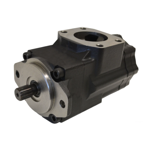
The bands below are planning ranges drawn from published press designs and supplier documentation, not a standard. Confirm the working pressure on the machine’s nameplate before specifying anything.
| Press type | Typical system pressure | Pump architecture commonly seen | What sets the limit |
|---|---|---|---|
| Workshop and H-frame, 5 to 200 t | 150 to 250 bar | Single fixed vane or gear | Simple valve circuits |
| General industrial hydraulic press | 200 to 315 bar | Fixed vane, variable vane, or piston | Tonnage and bore |
| Press brake, 30 to 400 t | 200 to 350 bar | Variable vane, piston, or servo-hydraulic | Cylinder synchronisation |
| Four-column deep drawing, 100 to 2,000 t | 200 to 315 bar | Main pump plus prefill, separate cushion circuit | Cushion pressure |
| Stamping and blanking | 160 to 250 bar | High-flow pump with accumulator | Flow, not pressure |
| Forging press | 250 to 350 bar | Piston, with high-pressure vane on older machines | Peak forming loads |
| Powder compaction | 200 to 350 bar | Piston or high-pressure vane | Long hold at full pressure |
Most presses live between 200 and 315 bar, which is inside the high-pressure vane envelope. The presses that exceed it have long, repeated full-tonnage holds, and those are the candidates for a different pump family.
Keep three pressures separate when you read a datasheet: approach pressure, pressing and hold pressure, and the pump’s rated pressure. A pump rated at 315 bar continuous is not being asked to do 315 bar for one second. It is being asked to do 250 bar for eight seconds, forty times a minute, for years.
Sizing a Vane Pump for Press Duty
Sizing runs in four steps, and each one uses a number you can get from the machine or the drawing.
- Tonnage to ram area. Area equals force divided by pressure. Choose the pressing pressure, then solve for the bore it implies.
- Ram area to flow. Flow equals area multiplied by pressing speed. Always state the speed; a flow figure without one is meaningless.
- Flow and pressure to drive power. Hydraulic power equals pressure multiplied by flow. Divide by the wire-to-hydraulic efficiency to size the motor.
- Duty to rating. Confirm the continuous rating at the actual speed, fluid, and oil temperature. The correction factors are in our guide to .
Ram area and tonnage
Tonnage in tonnes equals pressure in bar multiplied by area in cm², divided by 981.
| Bore (mm) | Area (cm²) | 160 bar | 210 bar | 250 bar | 315 bar |
|---|---|---|---|---|---|
| 200 | 314 | 51 t | 67 t | 80 t | 101 t |
| 250 | 491 | 80 t | 105 t | 125 t | 158 t |
| 280 | 616 | 100 t | 132 t | 157 t | 198 t |
| 320 | 804 | 131 t | 172 t | 205 t | 258 t |
| 355 | 990 | 161 t | 212 t | 252 t | 318 t |
| 400 | 1,257 | 205 t | 269 t | 320 t | 404 t |
Worked example: a 200-ton press
Suppose a 200-ton press needs 1.96 MN of force and runs at 280 bar during pressing.
- Ram area: 1.96 MN divided by 28 MPa gives 700 cm², or a bore of about 299 mm.
- Pressing speed: 6 mm/s needs 700 cm² × 0.6 cm/s, which is 420 cm³/s, or about 25 L/min.
- Drive power: 28 MPa × 420 cm³/s is 11.8 kW hydraulic. At 85% wire-to-hydraulic efficiency, a 15 kW motor covers it.
- Approach: 80 mm/s on the full area would need about 336 L/min, which no practical press pump supplies.
So what size vane pump does a 200-ton press need? There is no single answer, and a supplier who gives one without asking for bore and pressing speed is guessing. The defensible range is 25 to 40 L/min at 250 to 315 bar, with the exact figures set by the bore and the required pressing speed.
For series-level pressure classes, the guide covers which families reach which ratings.
Hold, pulsation, and what the press shop notices
Presses spend their cycle in hold, not in motion, and that is the phase a vane pump handles well. A balanced rotor produces low flow ripple, and a pressure-compensated pump holds pressure with almost no output instead of dumping full flow across a relief valve.
Low ripple matters because flow variation becomes force variation at the ram, then thickness variation in drawing and witness marks on the part. The Nippo design makes the trade explicit: 68 dB for the vane pump against 75 dB for the piston alternative.
For more technical information, please read our article on vane pump derating.
Decompression: The Phase That Damages Pumps
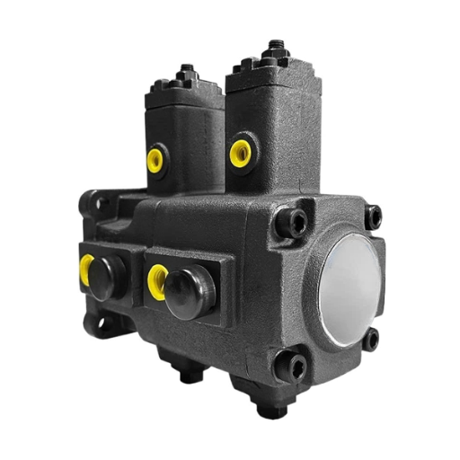
At the end of the pressing stroke, the frame, the oil, and the cylinder are storing energy. Releasing it in one step sends a pressure transient backwards through the circuit to the pump, the valves, and the pipework.
Good press circuits release it in stages. A decompression valve opens first and bleeds cylinder pressure down to a low value. Only then does the prefill valve open, so the surge valve does not slam open against full tonnage pressure. The pump is normally unloaded to tank while this happens, which keeps it out of the transient.
When the sequence is wrong, the symptoms are consistent:
- A knock at the moment tonnage releases, not during pressing.
- Seal weep that appears after a tonnage increase, with no change in oil or filtration.
- Cracked pipe or hose at the valve block rather than at a bend.
- Pressure spikes on a trace at decompression, but a clean trace during hold.
- Prefill valve hammering, or a ram that jumps before it retracts.
None of these are pump faults, which is why replacing the pump rarely fixes them. The fix sits in the valve sequence and the decompression setting.
Safety note: Opening a press circuit, adjusting a relief or decompression valve, or testing a pump under pressure requires lockout/tagout and a competent hydraulic technician. Stored energy in an accumulator or a prefill tank can remain after the pump stops.
When the Press Has Outgrown the Vane Pump
Vane pumps are the right choice for a large share of press work and the wrong choice for a recognisable share of it. The boundary is pressure and duty, not brand preference.
Press duty has outgrown the vane family when continuous working pressure sits above roughly 250 to 310 bar, when full tonnage is held for long dwells cycle after cycle, when the heat load rather than the force sets the pump size, or when the machine builder has already standardised on piston or servo drives.
Press builders rarely choose one family and stop. A hi-lo circuit uses a large low-pressure pump for approach and a small high-pressure pump for tonnage. A vane-plus-piston arrangement uses vane for approach and hold and piston for the forming stroke. A servo-driven fixed pump reverses through a closed loop between two cylinder chambers, which is the architecture in the Nippo patent.
What vane still wins: mid-tonnage presses, rebuild-and-replace economics on an existing machine, noise-limited shops, and circuits that need two pressure levels from one drive. The crossover arithmetic is in . For press work, below 250 bar, vane is usually the better economic choice; above 310 bar continuous, piston usually is.
For the full comparison, our vane pump vs. piston pump comparison covers the crossover decision.
Specifying a Vane Pump for a Press
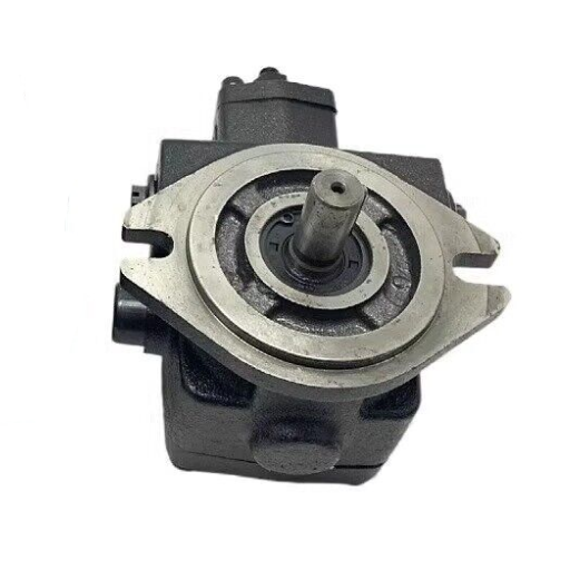
A press pump RFQ needs nine pieces of information. Without them, any quotation is a guess dressed as a specification.
- Press make and model, tonnage, and a photograph of the pump nameplate.
- Ram bore and rod diameter, or the cylinder drawing.
- Circuit pressures for approach, pressing, hold, and the relief setting.
- Pressing speed and approach speed in mm/s, plus strokes per minute.
- Cycle time and dwell duration.
- Existing pump: make, full ordering code, displacement, mounting, shaft, ports, and rotation.
- Fluid type, viscosity grade, and normal oil temperature.
- Filtration specification and the oil cleanliness the machine was built to.
- Whether the press has a prefill valve, an accumulator, or a rapid cylinder.
The one question worth asking every supplier is this: what is the continuous rating at my pressing speed, fluid, and duty cycle? A maximum pressure figure tells you what the pump survives, not what it will deliver for the next five years.
LOYAL INDUSTRIAL supplies vane pumps across the brands that appear on press duty, including the VQ and VQH ranges, Denison T6 and T7, Tokimec SQP, and Yuken PV2R. You can request a specification sheet and an application review once you have the nine items above.
To learn more information, please read our article on vane pumps for die casting machines.
Frequently Asked Questions
What size vane pump do I need for a 200 ton press?
Most 200-ton presses need roughly 25 to 40 L/min at 250 to 315 bar, but the figure depends on bore and pressing speed. Confirm the bore before ordering.
Does the hydraulic pump lift the press ram?
The pump supplies flow, and on small presses it does lift the ram. On large presses with a prefill valve, the descending ram draws oil from a tank, and the pump only builds pressure once the valve closes.
What is a prefill valve on a hydraulic press?
A prefill valve connects the main cylinder to a tank during fast approach, closes automatically when the pump builds pressure, and reopens on return to dump the volume back to the tank.
Can a vane pump hold pressure for a long dwell?
Yes, within its continuous rating. A pressure-compensated variable pump holds pressure with very little output. Check the rating at the actual oil temperature, because an intermittent rating is not safe for a press that holds pressure every cycle.
Why does my press pump fail right after the pressure releases?
That pattern points to decompression, not wear. A release that is too fast sends a pressure transient back to the pump. Check the decompression sequence and prefill valve timing before replacing the pump.
Is a vane pump or a piston pump better for a press?
Below roughly 250 bar continuous, a vane pump is usually quieter, smoother in hold, and lower cost. Above roughly 310 bar, a piston pump is better in efficiency and service life.
Conclusion
Choosing a vane pump for hydraulic press duty starts with the cycle, and the cycle has four phases with four different demands.
- Approach is a flow problem, solved by a prefill tank or a rapid cylinder, not by a large pump.
- Pressing is a pressure problem, set by tonnage and bore.
- Hold is a duty problem, and it is where vane pumps earn their place.
- Decompression is a valve problem, and it is where most press pumps are damaged.
Size the pump for pressing speed and tonnage, confirm the continuous rating at your real oil temperature, and check the decompression sequence before blaming the pump for a failure.
If you are replacing a press pump, send the nameplate photograph, the bore, and the cycle times. LOYAL INDUSTRIAL will map the duty against a balanced vane cartridge and return displacement, pressure class, mounting, and port options in one specification sheet. Contact us right now!