Choose hydraulic reservoir breathers to match airflow, allowed pressure drop, damp conditions, and the fluid in use. Replace or service the fitted unit as its own label and service guide require. Tank size or desiccant color alone will not tell you when it needs work.
A vent can look dry and still need a closer check. Can the complete assembly pass enough air? Is another opening bypassing it? Has the oil already taken in water?
Those are reasonable concerns when a replacement cartridge is due. This guide explains airflow, moisture control, and service checks. Use it to build a clear parts request and work record. Keep the machine limits in view; do not guess them.
Key Takeaways
- Establish air-in and air-out demand; tank capacity alone does not establish breathing flow.
- Compare airflow ratings with the actual valve configuration and permitted restriction.
- Read the fitted desiccant’s indicator instructions; color does not prove every filter function.
- Treat breather condition and existing oil condition as separate maintenance questions.
If water is already suspected, start with the guide to water in hydraulic oil alongside the checks below.
What hydraulic reservoir breathers control
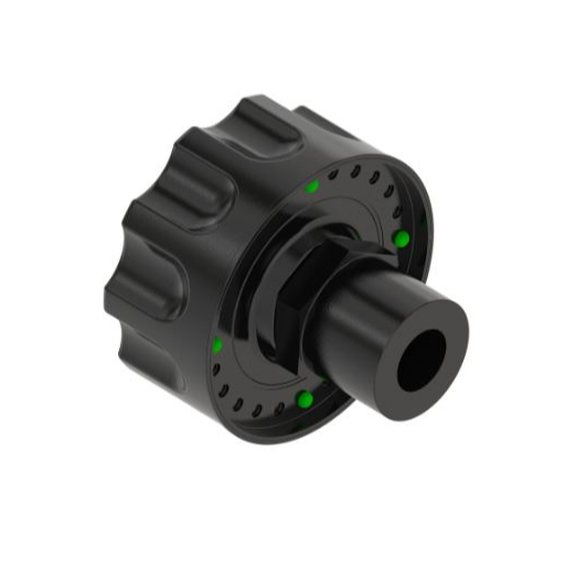
Air exchange as the oil level changes
The headspace is the air above the oil. When the oil level falls, the tank needs an inward air path; when the level rises, air must leave. Changes in operating temperature also belong in the equipment’s breathing assessment.
The tank stays the same size during these changes. How fast it breathes depends on the work it does. The volume on a tank drawing cannot tell you the whole story. Keep the reservoir volume, oil-volume change rate, and pressure limits as separate entries on your worksheet.
Incoming air can carry airborne particles and humidity. A suitable breather treats this air path before contaminants enter through it. It cannot protect a reservoir from every other source, such as an open filler connection or water entering elsewhere in the system.
Separate particle filtration from moisture protection
A particulate breather filters airborne solids. A desiccant unit adds material that adsorbs moisture from air. A non-desiccant arrangement may instead suit applications with water-based fluids or other specified conditions. Check-valve-equipped designs add controlled opening behavior; their pressure requirements must fit the machine.
Check each function on its own. A particle rating states how the filter performs in a given test. Adsorption capacity tells you how much moisture the drying material can hold. Neither tells you the installed assembly’s pressure drop at your required flow, nor a universal replacement interval.
Illustrative scenario: A maintenance team replaces a saturated cartridge after finding wet oil. The new part controls one possible entry path. Is the oil now dry? That needs a separate check.
The team still has to look for other entry paths and choose how to test and treat the oil.
Oil-side filtration is a different task. Use ISO 4406 cleanliness codes to understand a liquid particle report, rather than using that code as a breather specification. A particle result also does not measure water content.
Ask a clear question: what must this tank’s air path control, and where will it work? Answer that before choosing a cartridge by appearance, thread size, or a familiar brand name.
Size hydraulic reservoir breathers for the actual air duty
Establish the maximum credible breathing demand
Start with the machine’s hydraulic circuit and operating sequence. Find how fast the tank’s oil volume can change in either direction. Include filling, draining, and service work where relevant. A steady work cycle may not be the case that needs the most air.
Pump flow can be a starting input, but it is not automatically the net change in tank volume. Oil may return while the pump draws from the reservoir. Ask the OEM or the engineer in charge which work cycle sets the air demand. Check air going in and air going out.
For each case, record the oil-volume change rate, units, and direction. Where did that rate come from? Save the drawing, duty sheet, or approved test record that supports it. An unexplained number copied from an old purchase order is a poor basis for a retrofit.
Keep this work separate from hydraulic reservoir sizing. Tank capacity and thermal design matter, but two reservoirs of equal volume can have different breathing duties.
Use a flow conversion with its assumptions visible
TTI’s hydraulic tank breather sizing guidance gives a rough starting rule: divide pump flow in US gallons per minute by 7.5 to obtain cubic feet per minute. Its example gives 120 ÷ 7.5 = 16 cfm. Keep the US units in the calculation.
Illustrative scenario: Assume that a particular operating condition actually changes the reservoir oil volume at 120 US gpm. The rough conversion gives 120 ÷ 7.5 = 16 cfm of corresponding air displacement. That number starts the flow check.
It does not approve a breather with “16 cfm” on its label. The pressure-flow curve and the machine limits still matter.
This assumes the oil-volume change sets the air flow for that case. It does not set the allowed pressure drop. It also does not cover every work cycle or choose a check-valve setting. Do not mix US and Imperial gallons, or compare cfm directly with liquid gpm.
Check the complete assembly at the required flow
Get the pressure-flow curve for air going in and out. Check the full path, with the chosen adapter, valves, and pipes. What pressure drop goes with the listed flow? Compare that test basis with the pressure and vacuum limits for the tank.
Valve choice can change the rated flow. For example, Des-Case’s TDB Series specifications list the 93 Series at 25 cfm without check valves and 11 cfm with them. These are manufacturer-specific ratings, not recommended limits for your tank.
The valve option is part of the flow check. Do not leave it off the parts request.
Ask how the unit will stay within the machine’s limits as dirt builds up in the media. Use the maker’s service limits and approved margin. There is no single safety factor to invent for every tank. If pressure limits or the curve are missing, obtain them before approving the component.
The parts request should state air demand, allowed restriction, valve type, and the full assembly. A matching thread is only one check. It cannot settle the choice.
Match moisture protection to the environment and fluid
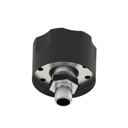
Describe exposure before choosing the design
Record whether the reservoir operates indoors, outdoors, or in a washdown area. Note humid process air, temperature cycling, dust, vibration, and long idle periods. Use these notes to check the design and plan access for service. Can staff read the label and inspect it where it will sit?
Desiccant takes up moisture from the surrounding air. Valves can limit contact with damp air while the machine is idle. Check their opening pressures and flow, too. They may not suit every tank.
Use the following comparison as a question list, not a product approval table:
| Operating situation | Question for selection | Evidence to obtain |
|---|---|---|
| Controlled indoor area | Is particulate-only protection appropriate, or is drying needed? | Fluid requirements and actual moisture exposure |
| Humid or intermittent duty | Would a valve-controlled design suit the air duty? | Opening pressures, flow curve and service instructions |
| Washdown or outdoor exposure | How will the air path avoid direct liquid exposure? | Approved location, housing suitability and cleaning procedure |
| Dust or vibration | Will the media, housing and mounting suit the duty? | Applicable construction and installation requirements |
Damp air is one possible source of water. It does not prove that water came through the vent. If the oil is wet, also check how the tank is filled, cooler leaks, and other possible routes.
Check fluid and installation compatibility
Check the fluid first. Do not choose desiccant just because water appears in its name. Water-based hydraulic fluids require their own compatibility review. Des-Case’s non-desiccant product information explicitly includes water-based-fluid applications; confirm the appropriate arrangement with the fluid supplier and machine manufacturer.
Also check exposure to oil mist or splash. Some designs include a splash guard or demisting feature, but the feature must suit the actual installation. More desiccant will not correct a poor mounting point or direct wash spray. Note where the spray comes from before choosing a new part.
Follow the fitted indicator’s instructions
Desiccant colors are product-specific. Trico’s February 2024 product update describes both orange/green and blue/pink options. There is no universal “replace at this color” rule.
Read the label or current guide for that unit. What is its starting color? How does it change, and when does the maker say to replace it? Record what you observe, preferably with a clear photograph.
A listed moisture capacity does not give you a service life in months. The air, work cycles, and dirt load can differ from one machine to the next.
Choose a design you can inspect and maintain under the actual operating conditions.
Inspect, replace, and record the fitted breather
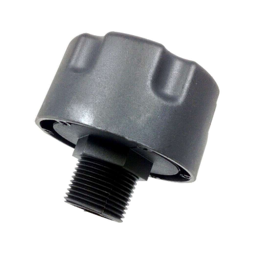
1. Identify the part and its service criteria
Read the housing label and record the maker, full part number, valve configuration, and installation date if known. Find the applicable instructions before opening anything. Establish whether the unit is disposable, rebuildable, or has separately replaceable elements.
Record the fitted indicator’s meaning, the approved restriction-check method, and any specified service limit. If the label cannot be read, compare the maintenance record and approved parts list. Do not use an unknown cartridge as the model for the next order just because it fits. Record the missing identity and seek the approved part details.
2. Make the machine safe
Use the machine’s approved shutdown, isolation, and pressure-release procedure. Control stored energy, supported loads, and tank pressure as the machine manual requires. Use those instructions for the shutdown; this guide cannot set the steps for an unknown machine.
Do not loosen a cap merely to find out whether the tank is pressurized. Confirm the design and required procedure first. Have the approved spare and clean tools ready. Keep the opening covered except when the work steps require access.
3. Inspect the whole air path
Check the housing for damage and the mounting for loose or damaged connections. Look for oil on the media, dirt outside, and signs of wash spray. Compare the setup with the approved drawing. Check other tank openings that could let untreated air in.
STAUFF’s installation and service guidance highlights bypass through a second untreated breather, unsuitable installation, and direct pressure-washer exposure. It also warns that solvent cleaning can damage its transparent polycarbonate housings. Use the cleaning guide for the fitted product. Do not assume the same cleaner is safe on every housing.
Illustrative scenario: A cartridge has unchanged desiccant color, but restriction is suspected. The technician notes the color, then uses the approved restriction test. That is a different check. The color cannot clear the particle filter, and running with the cap off is not a valid substitute.
4. Replace or service as instructed
Protect the open connection from dirt during the change. Check the adapter and sealing arrangement against the specified replacement. Follow the manufacturer’s orientation, sealing, tightening, and vent-opening instructions, including any shipping seals that must be removed for that model.
Do not guess torque, enlarge openings, or omit a valve to make a unit fit. Do not wash or bake a disposable cartridge unless its manufacturer explicitly authorizes that procedure. A serviceable assembly still requires the correct replacement materials and method.
Before restart, confirm the part number and valve type. Check that the air path is open. Remove temporary covers as the work steps require. Restore the machine only after its approved return-to-service checks.
5. Leave a useful maintenance record
Save this worksheet in the machine’s maintenance record:
- Machine identity, operating hours if available, and service date.
- Removed and installed part numbers, adapters, and valve options.
- Reason for work: indicator condition, restriction, damage, or scheduled inspection finding.
- Observed oil exposure, dirt, housing condition, and possible bypass paths.
- Instructions used, checks completed, and the person responsible for the next review.
Photograph the label and condition when useful. Record unknowns as unknowns. A note saying only “breather changed” cannot explain whether the original concern was saturation, restriction, or an incorrect application.
Verify the correction and handle repeated saturation
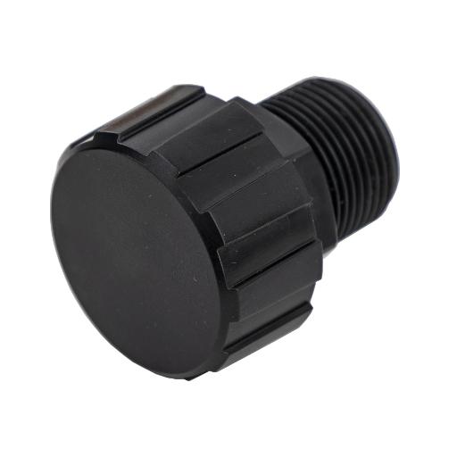
A new unit shows that a part was changed. It does not prove that the dirt or water problem is solved. Verify the installation first, then assess the oil separately if water or particles were part of the original concern.
Confirm the correct part, valve options, mounting, and service openings. During the approved operating check, use the machine’s specified observations or measurements. Write down any fault that is still present. A housing that looks normal does not prove that air flows freely.
Use recurring findings to choose the next investigation:
| Observation | Next check | Evidence worth retaining |
|---|---|---|
| Rapid desiccant change | Review humidity, washdown, duty and possible undersizing | Dates, operating conditions and indicator photographs |
| Oil-wet media | Review splash, mist, and mounting with the component maker | Installation photographs and fitted configuration |
| Damaged housing | Review vibration, impact, and cleaning compatibility | Damage location and maintenance history |
| Water persists in oil | Investigate other entry paths and the oil-treatment plan | Comparable samples, methods and repair records |
| Restriction recurs | Review particulate loading, assembly flow and service criteria | Approved restriction results and part identity |
Use these checks to look for a cause. They do not prove one.
A short service life can have several explanations, and a bigger cartridge may leave the actual cause untouched. Compare the setup with the approved design before changing size or valve settings. Keep the old part number and work record, so the next review has a clear starting point.
If the oil needs confirmation, use representative hydraulic oil sampling and keep the sampling point, machine condition, and laboratory method comparable. Then read the oil analysis report against the machine’s requirements and previous results. The indicator and the lab water test measure different things. Record both if both are needed.
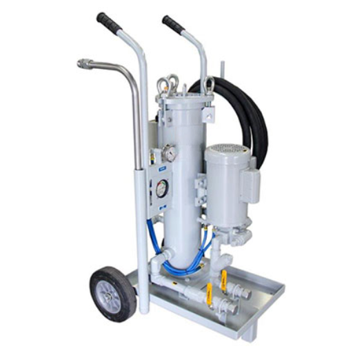
Where treatment is required, filter carts and kidney loops address a separate oil-side decision; the selected treatment must suit the contaminant and fluid. Breather replacement alone is not that treatment.
Close the work order with separate entries for installation acceptance, oil-condition findings, and the next review. If a fault remains, name the next check and who will do it. Do not record “fixed.”
Breather questions and the selection handoff
Does tank capacity alone determine breather size?
No, tank capacity tells you how much it holds. Breather size depends on how fast air must move and how much pressure drop is allowed. Find the fastest oil-volume change in both directions, then check the full air path. Use tank volume as context, not the only sizing input.
When should I replace a desiccant breather?
Use the service rules for the fitted part. Check its indicator guide, damage, and any required restriction test. A fixed date cannot cover every work cycle and climate. Record why the part was changed; if it saturates early again, look for the cause before ordering the same part.
Does unchanged desiccant color mean the air filter is clear?
No. The color indicates the desiccant condition according to that product’s instructions; it does not establish every particulate-filtration or airflow function. Check restriction using the approved method, and inspect the housing and installation. Do not clear a suspected blockage solely because the visible beads retain their starting color.
Can a breather remove water already in the oil?
It dries air that passes through it. Fitting one does not prove that water already in the oil is gone. Find the source of water and test the oil with a suitable method. Choose any oil-side treatment for the fluid and water present, then check the result against the machine’s limits.
Can I replace a pressurized tank cap with an ordinary breather?
Do not swap them without the machine maker’s approval. The cap and valves are part of a pressurized tank’s design. A matching thread does not prove a safe fit. Get the pressure and vacuum limits, valve details, and approved part type before changing how the tank breathes.
Prepare the selection handoff
Before requesting a replacement, gather the machine identity, fluid specification, existing part number, and clear installation photographs. Add the air-in and air-out duty, allowed pressure range, environment, valve configuration, and reason for the change. Mark missing inputs clearly. A blank pressure limit means it still needs checking; it does not mean the tank has no limit.
Keep the three example lessons in mind: a new vent does not certify dry oil; a converted flow does not approve an assembly; unchanged color does not prove unrestricted airflow. Each needs a different check and a different record.
For a hydraulic-component inquiry, use the contact route on the LOYAL INDUSTRIAL website and provide those details. Before ordering, confirm that the part is available and suits the job. The OEM or engineer in charge must approve changes to the machine design.