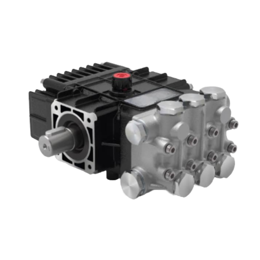
Ask ten people on a plant floor how a plunger pump works, and most will say the same thing: the plunger moves back and forth and pushes fluid out. That answer is not wrong, but it skips the part that actually matters. It never explains why the discharge pressure holds steady at 3,000 psi, why the flow pulses, or why the pump will not lift fluid out of a tank on its own.
When maintenance technician Ray noticed a triplex unit at his quarry losing pressure on every stroke, his first instinct was a worn valve. The real fault was a starved inlet. To understand both problems, you have to follow the mechanism from the crankshaft all the way to the check valve, one half-stroke at a time.
This guide explains how a plunger pump works in plain engineering terms. You will see the power end and the fluid end, the two-stroke cycle, the fluid path, and the stationary seal that lets a plunger pump reach pressures a piston pump cannot survive. If you need the broader context first, start with our plunger pump complete guide.
Plunger Pump Working Principle: A Working Definition
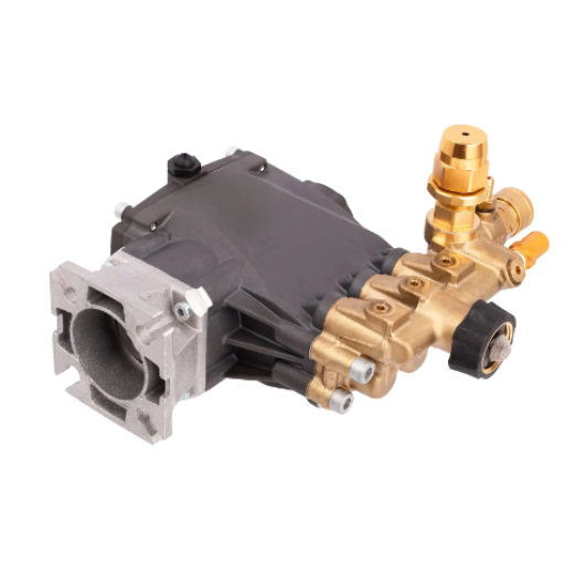
A plunger pump is a single-acting reciprocating positive-displacement pump. A smooth, precision-ground plunger reciprocates through a stationary high-pressure seal in the pump head, alternately drawing fluid through an inlet check valve and ejecting it through a discharge check valve.
That one sentence contains the whole working principle: a solid plunger displaces a volume of fluid equal to its own submerged volume, and two one-way valves keep the fluid moving in a single direction.
A Terminology Callout Before We Go Further
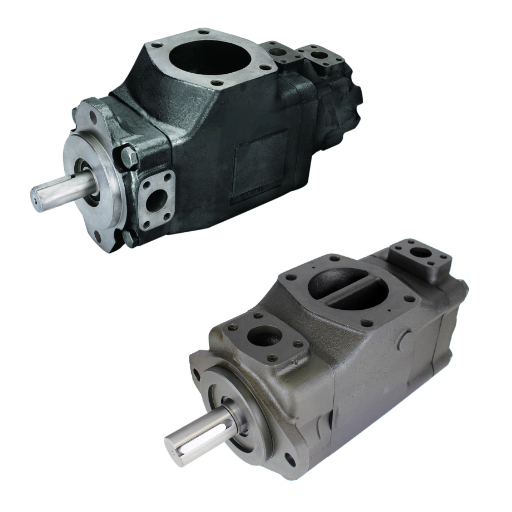
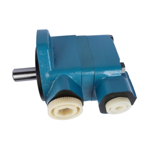
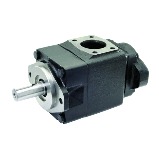
In hydraulic fluid power, the phrase “plunger pump” is sometimes used loosely for a piston-type hydraulic pump, such as an axial or radial piston design that circulates oil in a closed circuit. Those pumps are a different family. This article covers the process plunger pump: the reciprocating pump used for water, chemicals, and process fluids at high pressure. If your question is about closed-circuit hydraulic oil, our guide to hydraulic axial piston pumps is the right starting point.
The Two Halves of a Plunger Pump: Power End and Fluid End
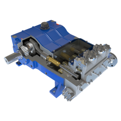
The plunger pump mechanism splits into two functional halves. The power end creates motion; the fluid end turns that motion into flow.
The Power End: Turning Rotation into Reciprocation
The power end converts rotary motion from a motor into low-speed reciprocating motion. As Engineers Edge describes the arrangement, a crankshaft driven through a gear reducer or belt connects to a connecting rod. The rod drives a crosshead that slides in a guided bore, and side rods carry that back-and-forth motion to the plunger.
One full revolution of the crankshaft produces one suction stroke and one discharge stroke for each plunger. Nothing about the plunger rotates. It only slides, which is why the fluid end can stay mechanically simple.
The Fluid End: Where the Fluid Actually Moves
The fluid end is where the work happens. It contains the plunger bore, the fluid chamber, and two spring-loaded check valves: an inlet (suction) valve and a discharge valve.
Unlike a piston pump, a plunger pump needs no cylinder liner. The fluid chamber sits between the two check valves, and the plunger enters it to displace fluid. A stuffing box packed with sealing rings and a gland nut forms the seal around the plunger. This seal stays fixed in the housing while the plunger travels through it, and that detail is what separates a plunger pump from every other reciprocating design.
How Does a Plunger Pump Work? The Pumping Cycle, Stroke by Stroke
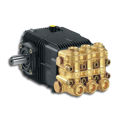
Understanding the plunger pump suction and discharge stroke means following one two-stroke cycle. Each stroke does one specific job.
The Suction Stroke: The Plunger Retracts
As the crankshaft rotates, the connecting rod pulls the crosshead and plunger backward, out of the fluid chamber. Chamber volume increases, so the pressure inside drops below the pressure at the inlet.
That pressure difference opens the inlet check valve. The discharge valve stays shut, held closed by its spring and by the downstream line pressure. Fluid flows in from the suction manifold to fill the growing cavity. By the end of the stroke, the chamber holds a volume equal to the plunger area multiplied by the stroke length.
The Discharge Stroke: The Plunger Advances
The crankshaft continues its rotation and pushes the plunger forward. Chamber volume shrinks, so pressure rises quickly. The inlet valve snaps closed, and the fluid has nowhere to go but out.
Once chamber pressure exceeds the pressure in the discharge line, the discharge check valve opens. Fluid is ejected into the discharge manifold under pressure. The cycle then repeats, once per revolution per plunger.
The Fluid Path Through the Pump
Follow one drop of fluid through the machine. It enters at the suction manifold, passes through the inlet check valve into the fluid chamber, and leaves through the discharge check valve into the discharge manifold. The two check valves make the pump direction-sensitive; reverse the rotation or cross the piping, and it will not pump. A pulsation dampener fitted on the discharge side absorbs the pressure ripple that the cycle creates.
The Stationary Seal: Why It Defines the Plunger Pump
The defining feature of a plunger pump is that its high-pressure seal does not move. The packing sits fixed in the stuffing box, and the plunger slides through it. In a piston pump, the seal travels with the piston inside a cylinder bore, so the seal presses against a moving, wearing wall.
That single geometric difference produces three consequences:
- Higher pressure ceilings. The seal is supported by a static housing instead of a moving piston, so it resists extrusion at far higher pressures.
- Longer plunger life. A smooth, hard plunger surface, often ceramic or coated, resists abrasion better than a piston’s sealing faces.
- More stable discharge pressure. The packing does not deform under load the way a traveling seal does, so pressure holds steady.
Here is the mechanism contrast in one view:
| Feature | Plunger pump | Piston pump |
|---|---|---|
| Seal location | Fixed in the pump head | Travels with the piston in the bore |
| Seal contact surface | Smooth plunger sliding through | Wearing cylinder bore |
| Typical pressure range | ~100 to 10,000 psi (higher in special duty) | ~100 to 1,200 psi |
| Self-priming | No; needs flooded suction | Often yes |
Why a Plunger Pump Produces Flow, Not Pressure
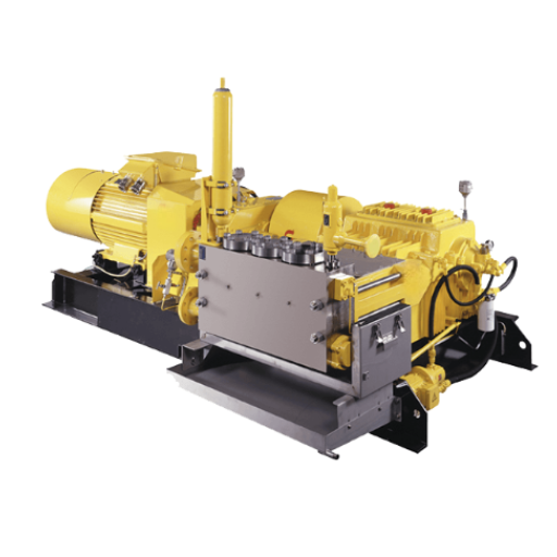
This point trips up first-time buyers more than any other. A plunger pump generates flow. It does not generate pressure on its own.
Pressure is simply the resistance the system presents to that flow. The pump displaces the same volume every stroke, regardless of what stands in the way. When that fixed volume meets resistance, pressure rises until the fluid moves or something gives. That is why every plunger pump needs a relief valve on the discharge line.
Ray learned this the hard way. His team once blocked a discharge to test a new spray nozzle and watched the line pressure climb past the gauge range in seconds. The pump kept pushing its fixed displacement into a closed line, and only the relief valve kept the manifold from failing. The pump was working exactly as designed; the test method was the problem.
Why Flow Depends on Speed and Displacement
Because the plunger displaces a fixed volume per stroke, the total flow depends on four variables multiplied together: plunger area, stroke length, number of plungers, and crankshaft speed. Nothing about fluid density changes this relationship.
A manufacturer expresses the same idea as an ideal-flow formula:
D = A × m × n × s × 6×10⁻⁵
where A is plunger area in square millimeters, m is the number of plungers, n is crankshaft speed in rpm, and s is stroke length in millimeters. The result is displacement in liters per minute.
Two trade-offs follow directly from this relationship. First, a larger plunger increases flow but reduces the pressure the plunger can safely develop, because the same force acts over a larger area. Second, plunger pumps cap their speed, typically at or below 600 rpm and often between 300 and 500 rpm, to control wear at the seal. When you need more flow without raising pressure, you raise the plunger count or the drive ratio, not the speed.
Why Plunger Pumps Pulsate, and How More Plungers Smooth It
Plunger pumps are almost always single-acting, which means each plunger discharges on only one stroke per revolution. The result is a pulse of flow on every cycle, and the rate of that pulse is set by how many plungers the pump has.
Increasing the plunger count is the simplest way to smooth the flow:
| Configuration | Pulses per revolution | Typical pulse amplitude |
|---|---|---|
| Simplex | 2 | Severe |
| Duplex | 4 | Moderate |
| Triplex | 6 | About +6% / −17% |
| Quintuplex | 10 | About +2% / −5% |
A triplex pump therefore delivers noticeably steadier flow than a simplex unit, and a quintuplex unit is smoother still. Where pulsation still matters, engineers fit a pulsation dampener or accumulator on the discharge line. The general rule is to size the dampener so its natural frequency sits well below the plunger-pass frequency.
At a waterjet cutting cell, the difference is not academic. A five-plunger pump feeding a cutting head holds a steadier stream than a triplex of the same flow, which shows up directly in cut quality and in the life of the downstream intensifier seals.
Are Plunger Pumps Self-Priming? No, and Here Is Why
A plunger pump cannot lift fluid on its own. The mechanism can only fill the fluid chamber when the inlet pressure is already higher than the pressure inside that chamber, so the pump needs a flooded suction or a positive inlet pressure.
For many designs, that means a supply pressure at the inlet of roughly 60 to 70 psi, with higher values permitted for some K-style configurations. When the supply sits below the pump, a booster pump or a gravity-fed header does the lifting.
The practical rule is simple: never run a plunger pump dry, and never assume it will prime itself from a tank below the pump. If the suction piping starves the inlet, the pump still cycles but the chamber never fills completely, so flow falls, and the valves hammer. That was Ray’s quarry pump exactly. The pressure loss on every stroke was an inlet problem, not a valve problem.
What Wears First, and Why
Understanding the cycle makes the wear pattern predictable. Three components take the most punishment.
The packing wears because the plunger slides through it on every stroke. A correctly set gland allows a slight, controlled drip; a seal that runs completely dry will overheat and fail early. Plungers score over time from abrasive fluid, chemical attack, or thermal shock, which is why ceramic plungers need careful handling. The check valves and their seats erode from the constant impact of opening and closing against pressure.
Frequently Asked Questions
How does a plunger pump work?
A plunger pump uses a reciprocating plunger that slides through a stationary seal. Retracting the plunger draws fluid in through the inlet check valve; advancing it forces fluid out through the discharge check valve. The fixed displacement per stroke produces flow, and system resistance converts that flow into pressure.
Does a plunger pump make pressure or flow?
It makes flow. The pump displaces a fixed volume each stroke, and pressure is the resistance the system offers to that flow. This is why a discharge relief valve is mandatory.
Why is the seal stationary in a plunger pump?
A fixed seal is supported by a static housing, so it resists extrusion at much higher pressures than a seal that must travel with a piston inside a wearing bore. That design choice is the reason plunger pumps dominate high-pressure duty.
Why does a plunger pump pulsate?
Plunger pumps are single-acting, so each plunger discharges once per revolution. A simplex pump pulses twice per revolution, a triplex six times, and a quintuplex ten times. More plungers and a pulsation dampener smooth the flow.
Are plunger pumps self-priming?
No. They require flooded suction or a positive inlet pressure, commonly about 60 to 70 psi for many designs. Never run them dry.
How is a plunger pump different from a piston pump?
The seal location: stationary in a plunger pump, moving in a piston pump. The plunger design reaches far higher pressures and holds them more steadily, while the piston design can self-prime and offers higher volumetric efficiency at low pressure.
Putting the Mechanism to Work
So how does a plunger pump work, in one continuous chain? The crankshaft turns rotation into reciprocation, the plunger slides through a stationary seal, and two check valves turn that motion into a steady stream of displaced fluid. Everything else, from the pressure ceiling to the pulsation to the priming requirement, follows from that chain.
Keep four takeaways in mind:
- The stationary seal is what lets a plunger pump hold high pressure without failing.
- The pump produces flow, not pressure; pressure is system resistance, which is why a relief valve is essential.
- Flow scales with plunger area, stroke, plunger count, and speed, and speed is capped to control wear.
- A plunger pump is not self-priming and needs flooded suction.
If you are selecting a plunger pump or replacing one, the next step is matching the mechanism to your duty. Send us the flow, discharge pressure, fluid, and inlet conditions, and LOYAL INDUSTRIAL PTE. LTD. will recommend a configuration and provide a technical specification sheet for your application.