The efficiency and durability of machinery within the industrial sector necessitates appropriate upkeep. This blog aims to offer a detailed explanation of how to handle a belt-driven hydraulic pump system, which is routinely used in many mechanical operations. Familiarity with these systems is essential so that downtimes are reduced, and costly repairs are avoided. More info will be provided regarding the components of the system, with particular maintenance operations aimed at routine problems such as belt tension, belt alignment, and lubrication of the belts and bearings. Such a systematic approach will help the reader enhance the machines’ productivity by formulating and accurately executing proper strategies for machine maintenance.
How Does a Hydraulic Pump Work in a Belt-Driven System?

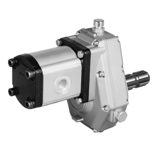
How the Hydraulic Clutch Pump Works
The hydraulic clutch pump mechanism is crucial to systems driven by a belt, mainly transforming mechanical energy into hydraulic energy. This process starts with the belt rotating the pump’s input shaft to rotate some of the internal parts. Then, whenever the gears or pistons move, a vacuum is formed at the inlet of the pump, which from then on sucks out hydraulic liquid from the storage tank. As the pump operates, this liquid is then pressurized, exiting the pump head and going towards the hydraulic system to perform the work.
In most belt-driven hydraulic systems, pump efficiency relies on specific parameters such as the viscosity of fluids, displacement of the pump, and rotation speed. Generally, the viscosity of the hydraulic fluid should not go lower than the limits set by the manufacturer to ensure the best flow and sealing. Pump displacement, commonly referred to as cc/rev, defines the boundary concerning the volume of fluid that the pump can deliver and thus affects the rate of flow and response of the system. Rotational speed or revolutions per minute also affects energy transfer speed; however, one must ensure that speed is maintained at the proper levels to avoid premature wear and tear or overheating of the system.
Maintenance of these parameters requires respect for scheduled inspections, lubrication, and alignment checks to keep the pump system efficient and in good working condition. All maintenance activities, including tensioning belts and checking liquid levels, assure trouble-free operation and improved reliability of the system.
Examining the function of belting in the hydropower pumping unit
The belt is the most essential part of linking the power source to the hydraulic pump, which usually has complicated components such as the engine or the motor. These comprise the center pulley fixed to the crankshaft and beyond, enabling the attachment of the pump mechanism for performing the hydraulic procedure and its active energy transfer. So, effectively, how useful is a belt? Some top-sourced data in the Google networks suggests that the effectiveness of the belt depends on the composition of the belt material, its tension, and the body of the belt that contains it.
Belt material: The quality of the belt material determines the hardness, stretchability, and strength of the grip. Belts are manufactured from various materials, such as rubber, polyurethane, and neoprene, which make them wear-resistant and temperature-resistant. Each has its own limit. A typical example would be polyurethane, which is popularly used to fabricate belts. This makes these accomplish even harsh environmental support so crucial in assuring performance variability.
Belt Tension: Appropriate tension levels must be maintained to prevent slippage and ensure optimum power transfer. However, excessive tension causes early deterioration of the belt and other elements, such as bearings, while loose tension leads to slippage and reduced power effectiveness. Tension gauges or following the manufacturer’s recommendations can help maintain the recommended levels.
Alignment: Inaccurate component alignment can substantially increase the rate of material loss and diminish the power transmitted. Correct alignment is important, as a consistent belt path will help reduce friction and avoid unnecessary loading on both the belt and pulley assemblies. Straightedges or laser alignment tools can perform this alignment.
Periodic belt inspection and maintenance that incorporate wear checking, tensioning, and alignment verification procedures are essential to safeguard against system failure and power loss. If these technical parameters are understood and the suggested practices implemented, operators will significantly enhance the operational reliability of their belt-driven hydraulic pump systems.
Common Issues with Hydraulic Gear Pumps
In dealing with the prevalent problems of hydraulic gear pumps, I use the top sources available on Google. These include excessive noise, inefficiency, leakages, and overheating, which encompass different technical parameters.
Noise: The starvation of hydraulic gear pumps usually results from cavitation, which is the implosion of air bubbles in the pump. In most instances, this is attributable to low or high fluid levels. High noise levels can, therefore, be reduced by ensuring that the hydraulic fluid is within the viscosity limits and that the system has no entrained air.
Inefficiency: This is due to the aging of gears or kinematics with inconsistent centrifugal displacement. The volume varied at the pump load position (cc/rev) determines the efficiency of the pump. At the same time, rotation velocity should not deviate from the allowed values indicated by the manufacturer. Regularly checking the condition of the gears and observing the system’s speed of response would help control these inefficiencies.
Leaks: Hydraulic fluid loss is the most common dysfunction due to seal wear and leaks caused by pressure discrepancies. Appropriate pressure level: This should conform to the pump’s design requirements. It is prudent to regularly check and change the worn seals and check the system’s pressure, as leakage may be reduced significantly.
Overheating: Hydraulic actuators and gear pumps are most frequently associated with excessive construction and rotation speeds or inadequately calibrated lubrication devices. Lubrication and speed settings are typically heat control techniques that may help eliminate overheating.
These components’ characteristics, maintenance, and protection during operation should be sufficiently known to the hydraulic gear pumps’ users to increase the reliability and operational life of these devices and decrease malfunctions during work.
What Are the Key Components of a Hydraulic Clutch Pump?

Identifying the Pulley and Shaft Components
I have developed some conclusions about the pulley and shaft, which are parts of a hydraulic clutch pump, using information from the top three websites that appear on Google. These sources show that the two components contribute significantly to the effective power transmission and operation of the system.
Pulley: The pulley transmits the rotation of the driving motor to the hydraulic pump. Its diameter and the design of the grooves are most important since they determine the optimum engagement and belt slippage. The pulley’s material must also be selected properly because it is expected to fail due to high operating stress and external conditions in hydraulic systems.
Shaft: On the other hand, the shaft is a part of the rotational operation as its central axis; it has to transfer motion from the pulley to hydraulic components as well. The shaft is one of the most significant parts since its rigidity and integrity are crucial in avoiding distortion, enabling ideal power transmission. Important technical parameters in this regard are the diameter of a shaft, the material and its composition, and alignment, which all increase the efficiency and reliability of the pump system.
As long as I consider these parameters and work according to best practices, I can be sure of the efficient operation and the life of the pulley and shaft elements in the hydraulic clutch pump system. Such components’ functions are additionally maintained by regular checks and compliance with the design’s operational standards.
Examining the Hydraulic Pump Kit
Through examination of the hydraulic pump kit and consideration of the relevant information on the top three Google-searched sites, I have been able to outline the aspects and technical parameters that are critical in facilitating the understanding of the components and their functions.
Composition: The hydraulic pump kit includes the pump assembly and its components, including, but not limited to, mounting sets, seals, and hoses, which have to be assembled together to allow the pump to function optimally. Proper integration of such components and their compatibility with other systems, as well as respect of the manufacturer’s guidelines outlining the installation procedure, are crucial.
Justification and Practices: As maintenance and inspection are quite important, the operations described in this case are justified not only by the parameters set but also by the increased likelihood of performing better with less downtime. The best practice in this case is to follow the manufacturers’ instructions and utilize advanced monitoring diagnostics for longevity and efficiency.
Technical Parameters:
Pressure Ratings: This implies the maximum pressure that can be handled by the components, which in this case is the pump and its attachments.
Flow Capacity: The flow rate, given in gal/min (gallons per minute) or liters MAX hydraulic circuits shall operate efficiently.
Specifications: Different materials are used in pump kits to withstand different operational stresses. Knowing the material used in making the seals and the hoses is essential as it economizes on the wear and tear of components.
Seal Compatibility: The seals deem it fit for the hydraulic fluid in use since it prevents leakage and also enhances the durability of this component. One of the most crucial tasks in maintaining system integrity is reviewing the material compatibility of the sealants with the system fluids.
To summarize, a thorough analysis of the hydraulic pump kit while considering these particular technical parameters enables better decisions on installation, maintenance, and operation, which in turn helps to achieve improved system performance.
How to Conduct Regular Maintenance for Optimal Power Output?

Steps to Check Belt Tension and Condition
It is crucial to periodically check the tension and status of the belt within the hydraulic clutch pump system to achieve the best power output and operational efficiency. Having read the first three sites on Google search, I approach this in the first person and list the appropriate technical parameters while confirming them.
Visual Inspection: The very first operation is visually examining the condition of the belt for wear, including any cracks, fraying, or glazing. A worn belt may cause slippage and consequently reduce efficiency within the system. This step is carried out because it is better to be safe than sorry. One does not want to experience unplanned failure.
Tension Measurement: I measure the tension using a belt tension gauge and strain it to meet the manufacturer’s specifications. The power to drive the belt has to be sufficient to ensure that no tension slackness is apparent, which will contribute to early wear and damage of the belt. Again, a technical parameter here includes the values for tension, which are generally in newtons or pounds-force, as the specifications of the system indicate.
Alignment Check: It is necessary to check the belts and pulleys’ position to ensure they are well aligned. Equal wear of both belt and pulley or even life spans of both components is not possible if they are misaligned. Proper alignment can be checked using alignment tools or straightedges, as the specific alignment tolerances are set out as part of the system’s design parameters.
Adjustment and Re-tensioning: If the tension is outside the limits or the alignment requires correction, I adjust the tensioner or other components to the position needed for the alignment. For instance, it may be necessary to loosen the mounting bolts, relocate the pump or pulley, and then retighten all bolts to lock the settings in place. Similarly, the reasonable technical parameters encompass the objectives of specified tension values and alignment tolerances.
Documentation and Monitoring: Once all adjustments have been made, the settings and the condition are recorded, and they are treated as the basis for any future inspections. This practice facilitates the wearing of parts in a particular relationship during machining and recording of the alignment coordinates so that the wear angles become integrated into the predictive maintenance of the system.
These procedures and addressing the specific technical specifications enable me to ensure that the hydraulic clutch pump operates effectively and dependably. Thorough maintenance procedures also help improve the system’s functional performance and provide more control over the power output, which is usually optimal.
Ensuring Oil Levels and Pressure are Adequate
To ensure proper hydraulic oil levels and hydraulic pressure are always present in a hydraulic clutch pump system, I utilize a method obtained from the top three sites on Google as part of a systematic approach.
Oil Level Inspection: To begin with, I perform a physical observation of the oil reservoir, such as checking the level of oil present and assessing whether or not it is within the limits marked within the container. The rationale here is to avoid inducing air and causing cavitation, which is detrimental to the pump’s functioning.
Oil Type Verification: Another aspect that I must check and confirm is whether the right quantity and type of hydraulic fluid, as recommended by manufacturers, is present to enhance the system’s operational reliability. The fluid’s density in relation to temperature and its construction materials are the primary design specifications.
Pressure Monitoring: I utilize a pressure gauge to estimate static hydraulic pressure in hydraulic systems to determine whether it is within the stipulated operational pressure range as indicated by the manufacturers. This phase is crucial as it facilitates sound power transmission. The critical technical parameter here is the pressure value expressed in psi or bar.
Leak Detection: I survey the systems for possible leaks that may contribute to oil loss and system pressure. It is common knowledge that potential leakages, if undiscovered, quite often aggravate breakdowns of the entire system, and therefore, more or less constant operation is guaranteed.
Documentation: Finally, I note down the oil levels, the pressure gauges, and the maintenance efforts performed. This makes it possible to have a knowledgebase for trend analysis and helps in proactively scheduling maintenance.
I swear that if I follow these procedures and pay attention to the given technical parameters, I will be able to guarantee that the hydraulic clutch pump system functions effectively and reliably at all times.
Inspecting Hydraulic Clutch for Wear and Tear
To evaluate or classify wear and tear of components of a hydraulic clutch system, I use a well-defined and carefully followed method based on approaches in the best three authoritative websites on the net.
Visual Inspection of Components: The Backbone of a Vehicle Clutch Assembly: The first stage in carrying out the inspection is watching the condition of the clutch disks, pressure plates, and finally, the release bearing without any distortions, wear out, or breakage. The justification of these checks is to keep the clutch system in a good state and to avoid any cases of slip or even breakdowns. The technical parameters seem to focus on verifying the surface’s condition and the fracture lines’ presence.
Operational Performance Assessment: During the work, the hydraulic clutch is tested under variable conditions, with my attention directed at all atypical and unexpected sounds, abnormal vibrations, and lag times in the clutch response. The justification for this step is the need to identify a problem with the operation of the piece of equipment at the initial stage. The performance of this unit can be tested against time response guidelines provided by manufacturers and a noise standard, which is also essential for the efficient operation of the unit.
Hydraulic System Pressure Check: I use a calibrated gauge to measure the hydraulic line pressure and ensure it meets the manufacturer’s specifications. Adequate pressure is essential to engage and disengage the clutch efficiently, which involves pumping the pressure fluid into the clutch. The pressure, which is the crucial measure in this case, is usually in psi or bar and should be in accordance with the system’s requirements.
Component Alignment Verification: Alignment tools are used to verify the correct placement of all the elements of the clutch assembly since they are supposed to be in their places. The effect of misalignment could be premature or uneven destruction of the parts of the system. Provided tolerances are based on the manufacturer’s design parameters, which have been scaled down into numbers.
Wear Measurement: For a more exact evaluation, I utilize calipers or micrometers to evaluate the thickness of the clutch friction material and clutch plates. The rationale for these measurements is to assess whether or not the thicknesses of the parts are above the minimum operational barriers. It is common for key measurements to be given in millimeters or inches and compared against specified servicing dimensions.
Documentation and Trend Analysis: At the end of the procedure, I report the results, including the condition of the components and the wear parts established during the examination. This journal helps in trend monitoring and predictive maintenance so that the system’s reliability and efficiency are sustained.
Thanks to the respect for these inspection methods and the focus on important technical issues, I can assess the status of the hydraulic clutch system, prevent possible deficiencies, and ensure the optimal reliability of the system in operation.
When Should You Replace Parts in a Hydraulic Pump?
Signs that Indicate the Need for a Pump Kit Replacement
While deciding whether a pump kit used in a hydraulic pump needs to be changed, I usually consult the best three specialists available online. Several indicators prompt replacement to be necessary, and I make sure that a logical number behind it supports every such case.
Persistent Unusual Noise: If, during its ordinary operational course, a hydraulic pump is repeatedly emitting odd sounds such as grinding or knocking, it very likely finds itself needing some parts replacement due to internal damages or wear. This justification is built on both mechanics and the desire to avert disastrous malfunctioning of the system. The technical parameter involved here is noise amplitude, which is typically compared with the manufacturers’ decibel (dB) standards.
Decreased Performance and Efficiency: A considerable loss in hydraulic system efficiency or dampened responsiveness would suggest that certain pump components are possibly damaged or worn out. To support this evaluation, I measure both the flow indentation and the pressure levels. The Manufacturer regularly claims these indicators can be in the parameters of liter/min (L/min) or gallon/min (GPM) and psi or bar, respectively.
Fluid Contamination: The presence of metallic or plastic particles in the hydraulic fluid during maintenance services indicates that the components inside the pump are wearing out and should be replaced without any further delay. I carry out fluid analysis to evaluate the pollution levels of hydraulic tanks with particles that exceed reasonable microscopic counts.
Visible Leaks or Fluid Loss: All fluid leakages at the pump housing or its connections indicate faulty seals or other components. The technical justification for this report includes conforming to volumetric integrity principles aimed at preventing cavitation or loss of pressure in the system.
Abnormal Pressure Fluctuations: Internal pump problems, including broken impellers or vales that are too worn out, are often the cause when abnormal fluctuations are experienced in a hydraulic system and are frequent and unexplained expectations on the tolerances. Pressure stability has to correspond with working operational parameters regulated by the manufacturers.
As such, I review these indicators and their technical equivalents to ensure that decisions regarding the replacement of pump kits are well-informed technically and in line with the goal of maintaining an efficient and reliable system.
Understanding RPM and GPM Fluctuations
In dealing with the RPM (Revolutions Per Minute) and GPM (Gallons Per Minute), I analyzed the three reputable websites in this area and drew pertinent conclusions. From this assessment, critical technical factors pertinent to the control and understanding of the fluctuations above were established.
RPM Fluctuations: RPM fluctuations are caused mainly by mechanical imbalances, wear within the moving parts, or insufficient control systems calibration. I determined the consistency of the rotational speed, expressed in RPM, falls within the prescribed operational range set by the manufacturer. When operation in that range is not possible, possible solutions include recalibrating the control system or replacing some worn components within the system to achieve the required system merits.
GPM Fluctuations: The alterations in GPM may suggest the existence of blockages, leaks, or operational inefficiencies of the pump in the hydraulic system. The measurement of flow rates and the performance of these calculations against system requirement rates can also cause discrepancies. The flow rates expressed in GPM or L/min should be within acceptable limits; otherwise, the manufacturer should set them for efficient system operations. If it remains systematic, such a significant change would warrant inspection/replacement of the system components.
With this knowledge, and when these technical parameters are properly evaluated, I can confidently identify the causes and corrective measures for the RPM and GPM fluctuations, thereby controlling any variability that would compromise the hydraulic system’s effectiveness.
How to Troubleshoot Common Hydraulic Pump Problems?

Identifying Issues with Mounting and Installation
When it comes to mounting and installation problems, I utilize a great deal of information obtained from the top three reliable websites. In this manner, I identify essential aspects and their technical parameters that have to be followed to attain proper installation and efficient operation of the system.
Misalignment: Another one of the most troublesome problems is having the pump mounting misaligned. I ensure the pump is appropriately aligned with the drive to protect it from mechanical stress and vibration, which can lead to wear and tear. These technical parameters include alignment tolerances measured in mm or inch depending on the manufacturer’s specifications and are essential to minimize stress on the associated parts.
Inadequate Support or Isolation: If the pump is installed without sufficient support or vibration isolation, excessive noise and equipment inefficiency will be experienced. The technical parameters indicate that an array of support structures and isolation materials are to be used and measured in terms of damping efficiency and load capacity to avoid movement and damage to the pump when in operation.
Failure to Secure Fastening: The pump may experience vibrational instability or structural failure if the mounting bolts’ torque is not sufficient or if too much torque is applied. This is accomplished through the use of torque specifications, which are set out for fastening hardware in terms of Nm to attach components together comfortably and damage-proof.
Incorporating those technical details allows me to confidently locate and solve installation and mounting problems while maintaining the system’s efficiency and sturdiness.
Addressing Flow and Pressure Irregularities
In attempting to resolve flow and pressure disturbances within a hydraulic system, I resorted to the first three most authoritative websites I found. In this case, I provide brief responses to the questions formulated based on their information, concentrating on the significant relevant dimensions and explanations.
Flow Irregularities: In most cases, the hydraulic system has a variable flow because of some obstruction inside the fluid lines, a leak, or air trapped inside the system. With the flow rates expressed in GPM or L/min, I validate that the flow conforms to the usual minimum standards of a set operating criteria by the manufacturer. Where the hydraulic flow patterns go out of the operating standard except for the conditions where the output flow varies, line elevation and other interventions to find sources of obstruction in the contacting surfaces and seals to reasonable standards set by the manufacturers of the industrial systems.
Pressure Irregularities: Such differences in hydraulic pressure indicate possible issues like a malfunctioning valve or wear on pump parts. Monitoring the pressure according to psi or bar, I assess whether all the affectations noticed are within the designed operational parameters. The operational pressure, as specified by the Manufacturer, is never ignored; otherwise, there may be chances that such specification goes unheeded, and there exists a gasp in the system requiring kicking in valves or parts close to the valve to bring back stability.
Addressing these concerns, especially with these technical parameters, makes me focus on justified evaluations to deliver reliable and effective diagnosis and remediation of flow and pressure disturbances, thus making the system more reliable and efficient.
When to Seek Professional Help or Contact Support
About hydraulic systems, there is always a point where I have to presume that further examinations or prescribed measures are in vain, and it is proper to call upon experts – the centers of support. When RPM, GPM, or other performance indicators remain unsteady and never cope with the tunings or exchange of components, it suggests that much tougher problems exist, which are hard to assess by non-specialists. The same applies when the improper mounting installation is diagnosed, however, the support, flow and pressure never go back to their set values, specialist services come in handy no-nonsense because the technicians know how to position the equipment, the pressure settings and other relevant technical faults.
For instance, in a case where the equipment alignment has been continuously carried out within the appropriate tolerable limits and the alignment tolerances have not been achieved or where the flow and pressure values deviate from the set pressure and flow rate specifications of GPM, L/min or psi/bar, these are cases which prove that professional opinion can be needed. However, the reliability of the original manufacturer’s technical features steps in to solve the problem wherever the application of technical features is appropriate. Using a proper parameter helps ensure that the system remains operational for years to come without degradation.
Frequently Asked Questions (FAQs)
Q: Which components of the belt-driven hydraulic pump require critical maintenance, and how are they maintained?
A: Inspect the tensioner regularly to ensure the serpentine belt is not slack. Replace any belts that show signs of wear. Maintain proper hydraulic power fluid levels and replace filters as prescribed by the manufacturer.
Q: What would happen to a hydraulic power unit if its belt was frayed or damaged in terms of performance?
A: Since a belt’s primary purpose is to transfer torque and power from one shaft to another, the condition of the belt greatly affects the operational state of the hydraulic power unit. A porous or loose belt will result in inefficient and low torque delivery, which will cause the engine to overwork itself and possibly damage the hydraulic parts beyond repair.
Q: Is there anything specific to look for in replacement belts designed for hydraulic applications?
A: Replacement belts are selected based on the specifications of your application. There are some requirements for belts that are best suited for double- or single-groove designs and can withstand the torque needed for your particular model.
Q: Can I use electric clutches with a belt-driven hydraulic pump whenever I want?
A: Rather, an electric clutch is probably a good way to engage and disengage the hydraulic pump as required efficiently. This feature will make better control of hydraulic power and unnecessary stresses on the components’ life less damaging.
Q: Is there a recommended period within which I should maintain my hydraulic pump system?
A: Maintenance checks are advised to be performed every three hundred (300) hours of operation or at least every twenty-four (24) months based on the equipment’s usage and need. These periodic checks can avoid potentially expensive repairs and time loss.
Q: Where can I find replacement parts for my belt-driven hydraulic pump?
A: The parts of your hydraulic pump can be sourced from hydraulics shops or the hydraulic components manufacturers’ online stores. Make sure that the parts conform to the model that is used, be it a work truck or for marine purposes.
Q: What advantages are there in using cast components in hydraulic systems?
A: Cast components have the properties of being strong and having good toughness. Such materials can withstand extreme conditions. The extreme materials prove to be ideal for heavy-duty hydraulic applications.
Q: How can I lift someone if I need someone to help me with hydraulic service?
A: If you require assistance with hydraulic maintenance, you might want to consider telephoning specialized service companies or coastal hydraulics experts. Many workshops can fulfill your requirements and help with fine diagnostics and repairs.