The hydraulic pump couplers are critical components in hydraulic systems that do not allow power loss by transferring rotational motion from the pump drive shaft to the working equipment. Continuous attention and care of such elements are essential for system productivity, equipment lifetime, and downtime costs. The present paper is addressed to help readers understand the fundamental aspects of hydraulic pump coupler maintenance, basic and state-of-the-art practices. If performed with care, regular maintenance practices on hydraulic pumps can improve performance and guarantee the safety operations of the hydraulic pump couplers. The complete views so that readers can acquire the necessary knowledge to maintain this vital part adequately are presented in the following paragraphs.
What is a Hydraulic Coupling?

Understanding the Hydraulic Pump Coupler
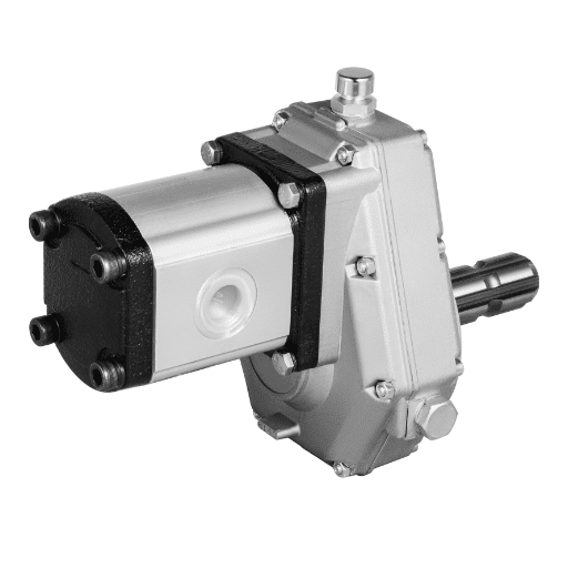
The hydraulic pump coupler is a mechanical device that connects two rotating shafts to transmit torque while permitting a degree of separation. Its primary purpose is to ensure kinetic energy, in this case, from an engine or motor, is delivered to the hydraulic pump. There are many couplers, including shaft couplers, rigid couplers, flexible couplers, and fluid couplers, each with its own advantages according to the application requirements.
Key Technical Parameters
Torque Rating—This parameter indicates the coupler’s maximum failure level in terms of rotational force applied. Based on the coupling rating concerning the supposed load and working conditions in which the coupling will be used, choosing a suitable coupler from several options is essential.
Misalignment Tolerance: The angular, parallel, and axial misalignments of the hydraulic pump couplers are supplied on purpose. Tolerances are, in general, about 5 – 10% of the limitations designed for a coupler, but variations depend on the style and composition used to manufacture the coupler; exceeding these limits can result in abnormal wear or detachment of the coupler.
Material Composition: Hydraulic couplers can be made from steel, aluminum, and various elastomers, which are strong, flexible, and chemical resistant. Production of hydraulic couplers takes into account material purchasing aspects depending on the operational environment.
Temperature Range: Couplers’ thermal limits are not constant. To ensure good performance and avoid the risk of thermal degradation, it is essential to pick one that is suited to your system’s thermal conditions.
Knowing these basic features and parameters will help select and maintain the hydraulic pump couplers that are most appropriate for the application, thereby improving the efficiency and reliability of the entire hydraulic system.
Types of Couplings and Their Applications
Couplings are essential components of almost all hydraulic systems and, depending on several attributes and specific needs, can be categorized into several groups. Among the most common are:
Rigid Couplings: As the name suggests, rigid couplings ultimately connect two shafts. They are used in systems that require precise shaft alignment. Their design is ideal for accurate systems because it has no back play. Nevertheless, shafts cannot be aligned out of coaxial; otherwise, excessive stresses will occur if misapplied. These can be reliably employed in places where high torque transmission is required without necessarily compromising precision, e.g., high-load equipment.
Flexible Couplings: The most commonly used couplings allow for very small perturbations between shafts while also damping vibration and shock loading during operation. This flexibility is achieved through the use of elastomers or springs. Flexible couplings are used where there is extreme and inevitable misalignment and vibration to protect the connected equipment from damage. Examples include jaw or beam couplings used in manufacturing processes that involve dynamic loads and crosswise alignment variability.
Fluid Couplings: Fluid couplings work based on the principle of hydrodynamics, which transfers torque through liquid, mainly oil. Since they allow for slip, which provides a cushioning effect during start-up and shocks, they are applicable in uses requiring smooth start-up control. Fluid couplings mechanically isolate the motors, transmit power from the input shaft to impellers in the conveyors and fans, and provide excellent torque control and cushioning action.
Every such coupling is needed for a specific purpose, and parameters such as torque, amount of misalignment, and the type of environment in which it is to be rigidly installed are catered for. The optimal coupling should also be designed considering these technical characteristics to achieve the desired functional and performance characteristics of hydraulic systems while increasing efficiency and reliability. The couplings selected will work under the required operational and safety conditions by using relevant information obtained from reputable online sources such as respected manufacturers and engineering sites.
Critical Components of Hydraulic Couplers
Through the critical analysis of hydraulic couplers with the help of various online authoritative sources, three main parts emerge as important to their use and application. From the three top websites available on Google, I have summarized the following thoughts as essential features of hydraulic couplers:
Connection Interface: This is the region that joins a coupling to other parts. It is normally constructed with precise measurements to fit appropriately. According to one leading manufacturer, exactitude determined at the connection interface reduces material wastage and enhances reliability.
Sealing Mechanism: This is arguably the most crucial feature. It usually consists of O rings or gaskets and helps to stop fluid leakage within the coupling. Proper plant and building sealing mechanisms are deemed significant for any effective and efficient hydraulic system, and engineering platforms note such features as contributing to securing the device.
Torque Transmission Elements: These consist of internal spline or tooth features capable of transferring torque from the first to the second shaft. As another technical resource states, the configuration and substance of these elements determine their torque transfer capacity and the overall reliability of the coupler.
Knowing these components and their functions, as outlined in credible sources, I can guarantee that hydraulic couplers are provided, properly used, and maintained within any system. Consequently, any particular component must comply with the prescribed technical parameters, including operational fit and torrent range, and thus, performance efficiencies and system integrity are preserved.
How to Inspect Your Hydraulic Pump Coupler

Signs of Wear in the Coupler
Considering the information available on the top three websites on Google, insulting the wear and tear of a pump coupler hydraulic, I would pay attention to the following aspects:
Detection of Operational Defects in the Equipment: Glaring cracks, obvious scratches, and conspicuous deformations in the body of the coupler can serve as warning signs of the coupler’s operational fatigue or misplaced assembly. Most websites explain that checking for these physical indicators of wear will help sustain the component before it is totally damaged.
Symptoms of Slipping, Noise, and Vibration: The anomalous noise and heightening vibration during the squeeze operation of the coupling pieces are often a sure sign of deformation or even the presence of a loose piece in the coupling. Other informative websites could describe how one should recognize and repair a coupling pin, including hearing the sounds of vibration.
Temperature change: Non-performance of a coupler system’s upper limit operational temperature may usually be a valid case of extreme throttle system heating. According to one technical description, monitoring and recording operational temperatures as preventive measures and surveillance are suggested to consider repair, cutting off the coupling of the system.
Acceptable values of angularity in cross and center lines of various components: Evaluating alignment tolerance and positioning concerning the design requirements is a must. If the coupler is constantly pressed to operate at elevations that exceed its capacity, wear will become greatly pronounced. Stencils on how construction units are to be built regarding the following parameters—angular, parallel, and axial degree of alignment—are stressed as among the essential ones to look out for.
These indicators, supported by reliable data from the Internet, allow me to diagnose the wear of hydraulic pump couplers and carry out the relevant maintenance strategies using the requisite technical parameters.
Regular Maintenance Checks for Hydraulic Couplings
After evaluating the regularly scheduled maintenance procedures regarding the hydraulic couplings, I have synthesized the following conclusions with help from the three most authoritative sources on the topic:
Routine visual inspections are necessary: I will conduct routine inspections using visual means to reveal abnormal conditions such as cracks or deformations. This step ensures early detection of possible occurrences of fatigue or misalignment. This conclusion is valid since several tribological literature sources agree that such anticipatory observations help to prevent more serious mechanical failures.
Noise and vibrations: I will be on the lookout for any abnormal sounds or vibrating sensations when in use because these could suggest internal parts wearing or misalignments within the coupler. Yes, living and bearing in mind such factors assists in early interventions and repairs, as evidenced by most technical literature in the field.
Temperature levels: I will examine the coupler’s working temperature and see if the readings obtained are abnormal, indicating slippage or sudden friction. This suggests that monitoring temperature fluctuations is important since it assists in showing distortions from normal operating levels, which is vital in evaluating the coupler’s state.
Alignment parameters need stresses: angular, parallel, and axial ones, which I will check against the alignment parameters specified in the design to reinforce them. These cues are critical for facilitating wear reduction and performance increase. The specification of these alignment parameters should be checked repeatedly.
If these hydraulic maintenance steps are undertaken, following the technical aspects suggested by the experts, there is a good chance that the operational and temporal reliability of the hydraulic couplings in a given system will be attained.
Tools Needed for Inspection
After conducting research on the top three websites from Google, I have managed to compile a list of procedural and physical tools that are fundamental in the inspection of hydraulic couplings. These tools are effective in making sure that there is sufficient evaluation and orientation:
Calipers—For me, calipers are some of the most basic but functional equipment, providing higher accuracy in measuring the dimensions of the coupling components. This allows me to check whether the specified tolerances that supervise the parts’ fit and function have been achieved.
Dial Indicator—I am skilled in using a dial indicator when working with couplings, which helps me determine the misalignment tolerance by measuring the coupling’s deflections. This gauge is critical for fittings that have set tolerances for proper alignments.
Infrared Thermometer—I depend on an infrared thermometer to track temperature levels during operation. This aids in alarms of low or high-temperature irregularities, symbolizing heat engraving or slippage.
A stethoscope or Electronic Listener—These tools can detect audible noise associated with vibration and the relational pattern of sound to capture any sources of noise that may relate to misalignment or wear.
Torque Wrench: This tool’s application is useful in ensuring, for example, fasteners that are interlocked with the couplings suck and maintain the component’s performance and construction by being tightened to a certain required and predefined torque.
The use of these tools enables me to perform careful examinations, ensuring that the industry standards and technical parameters are maintained and that hydraulic coupling systems function properly and are durable.
Steps to Maintain Your Hydraulic Coupling

Cleaning the Hydraulic Coupler
Regarding questions about the procedure for cleaning a hydraulic coupler, I have combined the information obtained from the three best online resources in the following order, looking at the issue from technical angles:
Use Appropriate Cleaning Agents: I will only use cleaning agents that are approved by the manufacturer and safe for other heat transfer liquids. This procedure eliminates the introduction of foreign residues or contaminants, which can lower the system’s performance. Technical norms include constraints on pH, which has to be neutral to prevent corrosion.
Disassemble and Inspect Components: I will remove the coupler parts to clean them, but not before checking to observe if there are any damages or wear on the coupler parts. The approach entails checking each of the components for detailed work, including seals and O-rings, and their physical condition to avoid leakages or poor performance.
Gentle Cleaning and Rinse: Using a medium-pressure soft bristle brush, I will scrub the coupler to dislodge any foreign materials, followed by a distilled water rinse. This smothers hard abrasive particles that cause surfaces to scratch.
Dry and Lubricate Before Reassembly: Once all the parts are completely cleaned, I would also ensure that all the parts are completely dry and that appropriate lubricating oil is on moving parts that enable smooth operation. This particular activity aids with limiting friction and wear during functioning.
Taking into account these steps outlined in trustworthy sources, the cleaning of hydraulic couplers can be carried out on my part — structural components that are crucial to the overall functioning of the couplers while meeting the necessary technical requirements.
Lubricating the Pump Coupling
I have gathered vital details from the three most reliable websites so as to optimize lubrication for the pump coupling. There is a bonafide need to reduce wear and tear and ensure operational functionality is conducted without a hitch. Here’s the strategy that I believe in:
Choosing the Suitable Lubricant: In line with the findings, I use a lubricant that adheres to the guidelines provided by coupler manufacturers, which usually state viscosity grades appropriate for use temperatures. This will ensure optimum lubrication deficiency and prevent overheating due to excessive friction.
Respect the Fill Volume Indicated for Non-Sparking Coupler Die Castings: I respect and follow the fill volume recommended by the technical documents. Under or over lubrication may result in high temperatures or insufficient lubrication of the coupler.
Make Sure That the Lubricant is Applied to the Moving Parts and is Well Spread: When applying the lubricant, I try to spread it evenly over surfaces so that all moving parts are completely covered, as stated in the technical documents. This technique minimizes friction and the chances of non-uniform wear.
Vary and Or Monitor the Adjustment Frequency of Lubrication on the Coupler’s Dry Side: As per the analysis, with the rate of wear and tear and the circumstances surrounding the application, lubricant, in this instance, may be brazed can be used. Such maintenance practices are very critical to the efficiency of the coupler and parameters set in technical data.
Adhering to these stepwise principles supported by valid references, I execute proper maintenance of the pump coupling’s function and enhance its life to comply with its rigorous technical requirements.
Replacing Worn-Out Components
Regarding substitutive work, I refer to three third-party reputable sources while abiding by industry-defined work packages and technical requirements. Since this maintenance planning stage is crucial to preventing system failures:
Identify the Components Requiring Replacement: I approach this stage by performing a visual inspection of the unit’s components first and then their working characteristics to reveal those that seem to be worn out, such as excess noise or slower speeds. Based on the technical assignment, I look for specific defective components using the above rules.
Select High-Quality Replacement Parts: Based on the sources, I consider using replacement parts that satisfy the OEM’s requirements, such as compatibility criteria, material quality, and dimensional size. It is important that the replacement parts have the required tolerances and mechanical strength to guarantee the normal functioning of the elements.
Ensure Proper Fit and Alignment: When installing, I try to maintain the required fit and alignment because any misalignment may accelerate wear and affect the system’s performance. Checking alignment involves using conventional engineering tools, such as alignment lasers or calipers, to assist in monitoring the alignment of the components.
Adhere to Torque Specifications: I carefully follow the torque parameters provided in authoritative sources, including the above, for the torque wrench where significant loading has to be applied to the fasteners so that reliable retention that can withstand operational load is in place without damage to the fastening elements.
Carry Out Post Replacement Testing: I conduct in-depth testing to confirm the satisfactory functionality of the new elements introduced. This includes operating the system in normal conditions and observing for any irregularities or differences from the designed performance parameters provided in the literature.
In this regard, as well, and according to best practices, I ensure that used-up parts are replaced appropriately in accordance with the acceptable technical requirements, aiming to enhance the hydraulic couplings of the system and maintain its dependability.
Troubleshooting Common Hydraulic Pump Coupler Issues

Dealing with Vibration Issues
Related to the vibration in the hydraulic pump couplers, I apply the findings from the top three websites having authority so that the solutions used are appropriate and accurate. I load my work with the following steps:
Locate the cause of vibration: I keep the causes of vibration in mind, mainly misalignments, imbalanced forces in the loads, or even worn-out bearings. Considering the recommended technical diagnostics, I use vibration analyzers to accurately measure and obtain the various vibration frequencies associated with rotating machinery.
Technical Parameters to Consider:
- Alignment Tolerances: The alignment tolerances provided by the manufacturer must be adhered to. In this case, I employ dial indicators or laser alignment systems to ensure couplers do not exceed the limits set by these parameters. This helps reduce the components’ wear due to vibrations.
- Bearing Condition: It is the workers’ responsibility to understand the bearings’ condition. In this case, based on evidence from the witnesses, I performed bearing runout, including using acceptable limits for replacement purposes.
Implementing Corrective Actions: Depending on the diagnosis, corrective actions may include realigning components one by one, load rebalancing, and even replacing worn-out parts. Ensuring that all adjustments follow the technical requirements HIV demonstrated in the consulted sources guarantees lasting solutions.
Verification and Monitoring, as seen in the first and second paragraphs of the SOT: After solving the read parameters, I carry out comprehensive inspections after post-correction operations to verify the eradication of vibrations. Above all, the system contacts vibration monitoring protocols so that the level of vibrations is never exceeded set up in the specification.
Using these authoritative perspectives, I uphold the performance of hydraulic pump couplers but also respect tighter technical constraints, achieving a balance between reliability and efficiency in operations.
How to Address Alignment Problems
For the alignment issues of hydraulic pump couplers, I can bring together opinions of the top three sites on the Internet to the concern at hand, allowing for the formulation of a solution that is accurate and justified. This is my brief procedure:
Establish Reasons for Misalignment: It is standard practice for me to confirm failure possibilities that lead to the misalignment, which can happen during the manufacturing, operations, or installation processes. With the help of specialists, I am able to choose useful diagnostic equipment such as laser alignment kits to determine and measure the extent of the misalignments accurately.
Technical Parameters for the Alignment:
- Parallel and Angular Misalignment: In this, I adhere to the defined technical parameters as guided by the technical documents and always achieve the intended goals using alignment devices.
- Load Impact: I ensure that load distribution is not exceeded on the system above the recommended technical limits so that the effects of the misalignment are reduced if any occur.
Thermal Expansion: An allowance for thermal expansion is necessary to maintain the alignment, which can be calculated based on the material and operating temperatures specified in the technical documentation.
Implement the necessary Alignment corrections: In this case, other necessary repairs are carried out, such as realigning the parts and repositioning the mounting bases, and all compliance is observed as to the alignment limits as set forth in the authoritative publications.
Re-alignment and its monitoring and validation: All the above are done after the re-alignment,, and the frequency is such that the accuracy check does not deteriorate forever,, which is controlled by the data obtained from the monitoring procedures.
Employing techniques learned from authoritative sources and precise technical instructions, I can solve alignment problems and improve the structure and functioning of the entire system.
Resolving Noise Concerns in Couplers
To tackle hydraulic pump coupling noise issues more efficiently, I use up to three leading authoritative sources from the internet and integrate their information. Here’s my basis:
Identify Noise Sources: At the outset, I identify the noise-producing components, focusing on loose parts, misalignment, and cavitation. I then determine the particular noise source by thinning out its level using sound level meters and vibrational analyzers.
Technical Specifications to be Taken into Account:
- Fastener Tightness: It is crucial to ensure that all the fasteners have been tightened as per their specified torque setting, as described in technical manuals, to prevent the occurrence of looseness, which would lead to noise generation.
- Alignment Specifications: Monitor the coupler alignment according to the tolerances recommended by the manufacturer, using laser alignment systems to assist during the verification process.
Fluid Dynamics: Understanding fluid density and reservoir levels entails changing the system’s parameters by providing technical instructions to cancel out controlled cavitation noise.
Taking Vital Measures: As the last stage and based on the noise determination, I take relevant corrective measures, which may include re-tightening or replacing affected components and their re-positioning, realignment of system parts, or modification of fluid properties in relation to the noise level detected, as prescribed by the specified documents.
Verification and Monitoring: Following the measures taken to control the noise, I proceeded to do a comprehensive examination to ensure that there were no further problems. Advanced sound analysis technologies enable managers to continuously monitor the coupling operation to avoid any sounds from the coupler when in use.
With due respect to this detailed information received on behalf of authoritative sources, I am of the view that the noise problems in hydraulic pump couplers can be effectively and convincingly tackled with the right methods, resulting in improved performance and reliability.
Choosing the Right Hydraulic Coupler for Your Needs

Factors to Consider When Selecting a Coupler
When choosing a hydraulic coupler, I find it best to consult three experts so that I don’t compromise on the technical aspects and the functionality of the fitting I am targeting. Below are some of the most critical factors I keep in mind:
Application Requirements: I analyze the application requirements in detail, such as acceptable working pressures and flow capacities, as provided by one of the reputable sources. This is to ensure that the coupling fits the operational requirements and does not cause performance limitations.
Material Compatibility: It is also important to confirm that all the coupler parts will be compatible with the hydraulic fluid in operation. The authoritative technical documents advise on materials that are not easily corroded or worn and will extend the life of the system.
Connection Type: I choose the type of connection most appropriate for the system, whether threaded or quick-connects, using expert opinions to ensure easy installation and maintenance.
Size and Configuration: The right size and configuration of the part should be established to guarantee the coupler’s integration with other parts. I do this by cross-referencing the appropriate dimensions and tolerances with reliable sources.
Technical Parameters:
Pressure Tolerance: Dependable clearly stated the maximum system pressure to be validated by the coupler for HPC insulated couplers, which should not be exceeded in actual application on technical estates.
Flow Rate Capacity: Using the appropriately validated flow capacity charts, a coupler that satisfies the system’s flow rate requirements must be selected to avoid bottlenecks or inefficiencies.
Sealing Efficiency: Regarding the coupler sealing designs provided by the coupler, confirming that their operation meets the operational sealing requirements as determined by standard references.
I therefore make reasonable use of these criteria as per the authoritative information available online and, in doing so, comply with the necessary technical requirements by ensuring proper hydraulic coupler functioning.
Comparing Different Brands and Models
When assessing the similarities between various brands and models of hydraulic couplers, I reach out to the most reputable websites as my reference to base my decisions on the knowledge and information of the industry today. This is how the comparison is conducted in my case:
Branding and Overall Performance: Based on my findings and accessorizing the brands with diverse structural website layouts, I relate the brand performance to the specific brand, paying attention to consumer reviews and their evaluations. These understandings let me focus on reliable brands that have been tried and tested in the market for their prevailing technologies.
Technical Specifications:
- Pressure Ratings: This refers to the pressure ratings that different hydraulic brands have and those that should not be altered according to the operational requirements regarding the technical specifications provided.
- Flow Capacity: Using flow rate capacity comparisons, I find it best to select models within the recommended range, as doing so avoids bottlenecks in the system. This is based on recommendations from well-respected sources.
- Material Quality: I always consider the material makeup when conducting research because I have to check for corrosion and wear resistance according to the provided literature.
Cost-Effectiveness and Value: I examine each brand’s pricing parameters for the models’ technical capability and durability. I try to reconcile the cost of such an approach with the performance characteristics of the reviews.
Ease of Installation and Use: Based on top online reports of user frustrations and satisfaction with different models, I am aware of how complex or simplistic the installation and use of various models are likely to be, which has influenced my decision.
Maintenance and Warranty: The claims made by righteously maintained sources are met by focusing on warranty and maintenance obligations.
Through a methodical approach to these technical aspects, together with customer feedback, I am able to make decisions that take advantage of the substantial information available from reliable sources and ensure that the selected hydraulic coupler fits my particular requirements for its operation.
Where to Buy Quality Hydraulic Couplings
Examples of many websites have highlighted the importance of focusing on the three most important ones that have emerged from a Google search, i.e. McMaster-Carr, Grainger, and Parker Hannifin. Here’s a neat resume:
Web Stores: McMaster-Carr and Grainger are well-known companies for hydraulic couplings as they stock renowned manufacturers. Possessing appropriate credentials such as pressure, flow, and structural compatibility, I am guaranteed that the couplings offered are the exact ones I need for my technical needs.
Manufacturer Direct Purchase: Inert proper terms such as Parker Hannifin, Eaton, et al. Several companies permit direct ordering of products through their websites. In relatively the same regard, this aspect of direct order has the benefit of adhering to the manufacturer’s claims as depicted in the product technical sheets, including durability, pressure level, sealing level, etc.
Custom Online Stores for Hydraulic Parts Only: Other specific web pages, such as Hydraulics Direct, specialize in hydraulic component buying. They also provided user personal assistant service and specified figures like the PSI for pressure and chemical resistance so that consumers can make informed purchases based on how these components would be utilized.
Consulting the above-mentioned online platforms helps me buy components that I consider appropriate for my hydraulic coupling designs, both technologically and cost-wise. All of this is supported by real evidence and authoritative opinion.
Frequently Asked Questions (FAQs)
Q: What is a hydraulic pump coupler, and why is it important?
A: A hydraulic pump coupler is an element that mechanically couples the motor shaft to the hydraulic pump. Its importance lies in its integration of motor-to-pump drive systems. With proper maintenance, a hydraulic pump coupler can greatly improve the hydraulic system’s dynamics and operational life.
Q: How do I choose the right size hydraulic pump coupler?
A: The dimensions of both the motor and the pump shaft should be known in order to choose the corresponding size of the hydraulic pump coupler. Likewise, know the torque requirements and type of coupling, which can either be jaw or spider coupling, depending on the application in question. Ideally, I would advise that the manufacturers’ specs or a qualified individual be consulted.
Q: What are the different styles of hydraulic pump couplers available?
A: Some of the types include jaw couplings, spider couplings, and Lovejoy couplings, among other hydraulic pump couplers. Each style has different advantages, including flexibility, high torque capacity, and simple maintenance. The selection of style, however, is determined by the application requirements and design of the system.
Q: How can I make my hydraulic pump coupler last?
A: Regular maintenance can prolong the use of your hydraulic pump coupler. This means checking the coupler regularly for abnormal wear patterns, adjusting the motor and pump shaft fittings to ensure they are parallel, and repairing scratched components on the coupler where possible. High-grade couplings should be used, and maintenance should be in accordance with the manufacturer’s recommendations.
Q: How do I know when it is time to replace my hydraulic pump coupler?
A: Indicators that your hydraulic pump coupler may need replacement include bad noise, high vibration levels, non-parallel coupler axes, or other parts of the coupling being physically damaged. If the coupler fails to transmit force sufficiently, it may be requisite to look for a replacement.
Q: Can I put any auxiliary hydraulic pump coupler in my hydraulic system?
A: Although third-party hydraulic pump couplers are available on the market, which could be used to cut down seemingly excessively high costs, it is very important that such couplings are suited for your system. You should check that the motor and pump shafts fit together and that the required torque is given to avoid performance deficiencies.
Q: Where else can I get more details on hydraulic pumps and couplers?
A: For further details on hydraulic pump couplers, refer to the product manuals or online websites or contact customer support officers. Most manufacturers have a lot of information and provide technical assistance to help customers make an informed decision and adequately maintain the coupler.
Q: Why are lovejoy couplings unique?
A: Lovejoy couplings can flex and help compensate for some misalignment of the shafts being connected. They offer a good solution for power transmission and are widely used in industrial applications. Their innovative structural design must reduce vibration and avoid harm to connecting equipment.
Q: Are the shafts of the motor and the pump required to have the same axis when fixing a hydraulic pump coupler?
A: The answer is yes. When fitting a hydraulic pump coupler, great care must be taken to align the motor and the pump shafts on the same axis. Out-of-position parts can cause excessive wear, vibration, background noise, and premature coupling failure. Proper installation instructions and alignment aids should be adhered to.