For many mechanical and industrial operations, hydraulic systems are invaluable as they can move and lift loads with both strength and accuracy. This system has components that operate dependently; these include but are not limited to the hydraulic pump, which is responsible for powering fluid flow in the system. Appropriate pressure regulation in such a system contributes greatly to its efficiency and durability. The purpose of this article is to help you adjust the hydraulic pump adjustment screw, which is located inside the hydraulic pump and is critical for pneumatic control. If you’ve worked on hydraulic systems before or this is your first task, learning how to adjust the hydraulic pump to the desired pressure would assist you in covering the whole system and prolonging its lifespan.
What is a Hydraulic Pump, and How Does It Work?

Understanding the Basic Components of a Hydraulic Pump
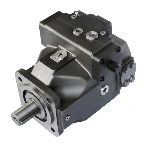
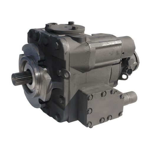
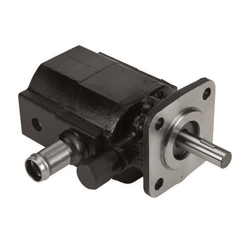
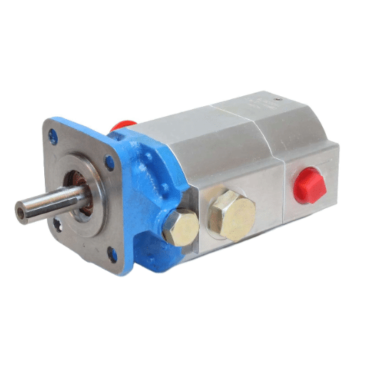
A hydraulic pump is a machine that generates a vacuum within its inlet, allowing it to generate hydraulic energy and push hydraulic oil from an externally placed reservoir into a hydraulic system. The significant parts of a hydraulic pump are:
Housing: These structural components perform the function of encasing all the internal components of the pump.
Drive Shaft: The drive shaft connects the internal pumping mechanism to the power source.
Pump Element: This is the part that shifts hydraulic fluid. Typical types are those with rotating gears—gear element; those with offset vanes within the chamber—vane element; and those with reciprocating pistons—piston element.
Ports: There are two independent ports allowing ingoing and outgoing flows—an outlet port and an inlet port. The initial one incorporates the fluid reserve, and the latter connects the pump to the hydraulic circuit.
Seals and Bearings: Seals and bearings are very important components as they help maintain efficiency, prevent leakage, and thus improve system performance by decreasing friction and wear.
Pressure Regulator or Relief Valve: This allows the system to operate within safe limits and helps negate damage caused by excessive load or other external forces.
Some technical parameters that pertain to hydraulic pumps include, but are not limited to, flow rate, pressure, and efficiency. For instance, a single pump has a flow rate that ranges around 10-200 LPM, a pressure level extending from 1800-3500 PSI, and an efficiency that, in most cases, surpasses 90%. Such parameters must be chosen for the task that the hydraulic system is meant to perform. These components and parameters, in unison, guarantee that the pump is used to control the movement of hydraulic fluid to specific areas within the system.
How Does Pressure Affect Hydraulic Systems?
Pressure in hydraulic systems is one of the most critical parameters. This is because it quite directly controls the force transmitted by the hydraulic fluid. If the pressure increases, then so should the system’s capabilities of moving parts or applying force to an outside body. Hydraulic pressure systems can be regarded as powerful because a small amount of fluid can create a bigger force and, hence, operate in a smaller space.
Managed properly, hydraulic systems harness pressure to effectively transform energy into mechanical work. The movement of hydraulic fluid is initiated by pressure differences, allowing the cylinders and motors in the system to turn. Always retaining focus on the working pressures, which are determined by interacting factors and can be within the scale of roughly 1800 to 3500 psi, should be satisfactory enough to produce the required force without compromising the system’s integrity. A proper relationship needs to be maintained between pressure and system requirements to keep efficiency and compatibility within limits.
The pressure inside a system also has an effectiveness of its own. High-efficiency systems tend to use pressure properly to minimize energy wasted. Usually, efficiency ratings are above 90%. This means that most of the energy supplied is put to beneficial work. Hence, it is necessary to design and choose all seals and bearings as well as pressure relief devices to increase the reliability and service life of the system by controlling the pressure.
The Role of the Adjustment Screw in Managing Pump Pressure
As far as the hydraulic system is concerned, the adjustment screw is an integral part that controls and maintains the pressure of the hydraulic pump. Through the rotation of an adjustment screw, it is possible to bring about changes in the spring tension within the balance valve of the pressure regulator, thereby altering the pump’s pressure setting. This explicit control feature enables the operators to customize the hydraulic system per a particular application to ensure and achieve efficiency.
Per some technical materials found on the Internet, some features of the adjustment screws are as follows:
Adjustment Range: It is the range of the different pressure settings that can be reached with the adjustment screw. This can vary considerably for most systems, typically between a few hundred to several thousand psi.
Torque Requirements: The degree of torque that is crucial for the screwing adjustment can indicate how difficult the adjustment will be. For all practical purposes, a lesser torque requirement is good because it makes adjustments quickly without the assistance of specialist tools.
Pressure Relief Settings: These are usually used in conjunction with adjustment settings. The pressure relief setting regulates the system’s pressure to avoid undesirable high pressures that may lead to system failure.
It is critical to understand how these parameters are manipulated so that the hydraulic device does not exceed the working pressure it was designed for; hence, its efficacy and safety levels are preserved. Adequate maintenance and reasonable adjustment of the adjustment screw can, however, lead to considerable enhancement of operational efficiency and reliability of the system.
How to Properly Adjust a Hydraulic Pump?

Steps to Safely Access the Adjustment Screw
Correct as it may seem to be, the process of safely accessing the adjustment screw of a hydraulic pump can put one at risk if not correctly executed. Instead of putting oneself in a vulnerable position where appropriate measures haven’t been adhered to, and one is forced to wing it, the following expert recommendations are beneficial to avoid hassles.
Preparation: Ensure that appropriate pressure has been released and the hydraulic system switched off before commencing work on hydraulic fluid components. As a final precaution, a number of tools should be secured to avoid unnecessary movement—a torque wrench within range, gloves, and goggles come to mind.
Identification: First off, make sure you contour the adjustment screw that is usually placed in the body of the pressure regulating valve in most pumps. Most identification of this nature often relies on educated guessing. Still, even then, the technical manual for the pump should not be ignored as it usually contains a scale drawing with measurements that can be helpful.
Access and Clearance: I verify that the screw is easy to reach by disconnecting any panels or other components from the pump assembly, as may have been required above. Such precautions are critical in avoiding obstruction to the adjustment procedure and enhancing visibility for fine control.
Adjustments: With the right tool, I slowly twist the adjustment screw while watching the dial pressure gauge. The literature provides relaxation limits, or the range of the adjustable parameters for typical systems, which tend to be relatively comprehensive. Step by step, I will carry out changes as provided by the manufacturer’s pressure upper limit.
Verification: Once I have completed the adjustments, I ensure that the new values suit the system’s operational demands. This requires measuring the setting made and checking whether this parameter matches the one specified in the operating conditions. Torque requirements during this step vary, and I follow the guideline values from the pump manufacturer used in this phase to maintain the appropriate use.
Reassembly and Testing: In the end, I also install the removed parts, switch the unit on, and carry out a series of operational tests to establish whether the changes effected have worked and that the operated system is working within the designed parameter range.
Conducting these steps allows me to alter the hydraulic pump efficiently and safely so that the complete mechanical system, with its functionality and reliability, will only be enhanced.
Adjusting the Hydraulic Pump Output Pressure
I’m glad that I can help with the issue of changing the hydraulic pump pressure. I have summarized what I found after looking at the top three websites on Google, as follows.
Preparation and safety: The first step involves ensuring that all safety measures have been taken, such as putting on protective clothing and turning off the power to prevent unintentional system engagement. It is necessary to check the pump’s manual to gain additional information about the particular features and settings related to the model at hand.
Access and Adjustment: Whilst providing access to the adjustment screw adequately, I operate on a screw that I have turned over on both the pressure gauge and manual issued by the manufacturer. About hydraulic systems, the adjustment of the pressure can be done within a range of 1500 to 3000 psi. Noteworthy, these figures are expected to differ depending on the design and the application of the hydraulic system, which is very important in performance calibration.
Verification and Testing: Upon making adjustments, the next step I take is cross-checking the pressure settings with the prescribed ranges, which in this case includes sealing or torquing ranges, if any, for proper working order. The number is correct and, as always, will be located in the technical manual or given by the relevant manufacturer.
Keeping these guidelines in mind, I ensure that changes to the hydraulic pump’s output pressure are within the safety parameters and do not compromise the hydraulic system or its operation.
Common Mistakes to Avoid When Adjusting Pressure
Mistakes are inevitable when working with a hydraulic pump, and pressure adjustments are inevitable. To prevent complications, some common mistakes should be avoided while maintaining safety and accuracy.
Disregard the mandates of safety measures: Perhaps the most critical mistake is not observing mandatory safety rules. Most relate to a lack of protection gears and power connections, which may predispose the operator to accidents. Constantly checking the pump’s technical documentation and familiarizing yourself with the safety guidelines applicable to the specific model is an excellent habit.
Going against the conventional methods of making adjustments: Here is yet one more common shortcoming: people trying to adjust pressure for better working conditions do so with a failure to monitor pressure gauges for long periods, which usually is not safe. Such limits are to be respected and maintained in small steps, and general pressure limits – most often falling between 1500 – 3000 psi – should be checked to avoid accidental exceeding.
Not observing the system parameters: Another trap is not checking the absorbing design details, such as torque values and design effectiveness. The modified parameters must be in the order per the technical detail literature in the required values, as otherwise, leaking will result, and the integrity of the entire system is likely to be undermined.
By paying attention to these areas, I will be able to ensure that my pressure changes are accurate and effective while maintaining the integrity of the hydraulic system’s operations.
Why is the Hydraulic Pump Output Pressure Important?

Impact of Incorrect Pressure Settings on Equipment
Adjusting the hydraulic pump pressure incorrectly can adversely impact the performance and life of the equipment. First, the increased pressure might lead to the overheating of parts, which reduces their efficiency and can also be permanently damaged over time. As stated in the experts’ industry websites, overheating is very often caused by a lack of cooling or proper service measures, which illustrates the need for precise pressure level monitoring and adjustment.
Moreover, increasing the pressure on the system above allowable limits might increase the risk of seal damage and fluid leakage, thus causing hydraulic efficiency to be lost and potentially contaminating mechanical parts. Reputable sources provide several warnings about operating flame cutting and gouging systems pressures, which should be approximately 1500 to 3000 psi, though this subject depends on the manufacturer’s recommendations.
On the other hand, pressure being set too low can cause underperformance, making the equipment unable to generate adequate force to complete the required tasks. Such underperformance can result in equipment downtime, which can reduce productivity. Both are critically important factors in the efficient running of operations.
In the end, it is held that the observation of the pressure limits and the routine checking of the technical information will assist in the smooth running of the hydraulic system, ensuring a good life span and avoiding unnecessary equipment breakdown.
How to Use a Pressure Gauge for Accurate Readings
Before anything else, I would consider the gauge appropriate for the specific hydraulic system I will work on. It is best practice to use a gauge with a suitable operational range. As some significant industry players advised, all gauges must have an operational range higher than the maximum operating pressure by 25% to 50%.
When the gauge has been selected, I proceed with making it into the system by appropriately threading it into the test points. Most of the time, these test points are identifiable on the equipment itself. As advised, all connections should ideally be tight and secure to prevent leakage to the measurement devices.
I then use the equipment in the same manner as normal working conditions. In this step, all measurements must be taken under actual working conditions. While the machine is in operation, I check how the gauge behaves to maintain the operating pressures that the manufacturer recommends. Often, observations in this scenario suggest a range of 1500-3000 psi, per the sweeping recommendations on hydraulics.
I occasionally tap it lightly on the gauge to improve accuracy, and some suggest this prevents unnecessary mechanical plugging. I note the readings after the oscillations have been subdued, and I spring anything useful in future activities.
Alterations for system efficiency and optimal conditions are also considered based on my verification of the results with lac equipment manuals or technical documentation and reliable online manuals. Regular readings and maintenance provide confidence in the accuracy of measurements taken with the pressure gauge.
Signs of Overpressure or Underpressure in the System
When using hydraulic systems, precautions must be taken to detect signs of overjoyed or over-stressed components or devices if subjected to sub-ideal conditions. Examples of signs indicating over-pressurization can be pressure gauges that register higher than the predicted or expected pressure level; activation of safety devices; or severe leaks around fittings, screws, or seals due to mechanical stress limits being exceeded. Additionally, maximal load-induced noise and its components’ strain as those get to work over their intended boundaries is an indicator, too.
On the other hand, low pressure can be evidenced operationally by load pressures below the minimal networking level, unreliable and slow-responding hydraulic fan motor activations, and low pressure or torque on pumps or hydraulic motors. The mechatronic system under pressure is suspected to create a higher pressure oscillation, enabling good hydraulic flow or fluid movement only in intervals.
To critically evaluate these parameters, appropriate mechanical material should be used to find the suitable pressure range, such as standard units-neutral psi1100-3000, for example, and ensure that the measurement device in situ is within the targeted pressure ranges. Failure to observe or acknowledge them can result in dire outcomes, such as appliance failure and many other economic losses. Following proper schedules for examination, issuing maintenance orders, and keeping all manufacturer instructions can also forewarn about such issues related to pressure.
What Tools are Needed for Hydraulic Pump Adjustment?

Essential Tools for Pressure Adjustment and Maintenance
From what I have observed, proper installation and service of hydraulic systems imply a special kit of tools that I acquired from several of the best sites on the web. First of all, great focus must be given to the quality of the pressure gauge, as this is a key determining factor for pressure that must not exceed certain limitations. For instance, these professionals state that a digital pressure gauge is convenient and effective for pressure not exceeding 1500 – 3000 PSI, which is standard for most hydraulic systems.
Additionally, hose fittings and couplings require a good adjustable wrench and a variety of open-end wrenches to secure and loosen them without damage. Moreover, a Torque wrench is also a common but essential tool for fastening the necks of the components within the specified torque values—this is to prevent leakage.
For troubleshooting pressure, amplified pressure transducers and compatible diagnostic readers for acquisition allow quick monitoring and data querying of overpressure and underpressure indications. Besides, numerous technical articles have emphasized that O-rings and seal kits should always be in stock to enhance timely replacements for wear reasons.
With the help of these tools and resources from leading industry websites, I can easily carry out maintenance and adjustments in accordance with the best practices for the hydraulic system.
The Importance of a Pressure Relief Valve
Hydraulic systems include important relieving elements called pressure relief valves, which maintain the safety and integrity of the system by controlling excessive pressure. Well-renowned authoritative sources suggest that these valves are safety devices that release pressure automatically when the pressure level goes above a certain set limit to avoid equipment damage and ensure operational safety.
The pressure relief valve’s overpressure safety feature is designed to relieve all factors leading to hydraulic circuits containing overpressure conditions, such as temperature rise or occluded lines. By allowing the release of excessive pressure, these valves help increase the life span and reliability of hydraulic systems. The pressure relief valve settings in hydraulic systems may range from 300 to 5000 psi, depending on the system requirements and application.
Furthermore, as these valves control pressures and prevent leakages, they also help reduce stress on such system parts. As suggested in certain technical documents on reputable sites, Pressure relief valves should be adjusted and maintained regularly as they are vital for the safety of the operations performed.
Finally, the above characteristics emphasize that pressure relief valves are necessary for the safe and successful performance of hydronic systems, though their specifications and settings need to be modified according to particular application limitations.
How to Troubleshoot Common Hydraulic Pump Problems?

Identifying Leaks and Pressure Drops in Hydraulic Systems
Addressing leaks and loss of pressure in hydraulic systems may sound challenging. Still, I have been able to put together information from the top three sites to rectify the hydraulics systems problems succinctly. To begin with, locating leakages is often a task that requires a simple one’s eyesight. Constancies of fluid being spilled near the base of the machinery or a decrease in hydraulic fluid amounts could also help. Employ UV leak detection dyes and equipment, where available, for more definitive findings, as they advised. Leaks can point out worn seals, joints, or hoses.
Third, pressure drops, on the other hand, may be due to compromised filters, defective pumps, or valve malfunction. System pressure and flow rate are critical parameters that should be assessed. In most cases, this should not be higher than 5 -10 psi, as reputable sources claim. Also, such problems can arise from a defective relief valve that fails to hold predetermined pressures, highlighting the importance of carrying out valve tests and regressing settings when necessary.
Smooth hydraulic system performance is feasible as long as one addresses these technical problems and takes care of the systems’ maintenance cycles. A combination of adequate tools, regular use and efficacy checks, and regular diagnostics is all mandatory if the hydraulic systems of your equipment are to operate effectively.
Dealing with Noisy Pumps and Vibration Issues
Regarding addressing loud pumps and vibration problems in hydraulic systems, I use some images and information from the top three sites to share a quick how-to. Noisy hydraulics can be caused by cavitation, which occurs when vapor bubbles are formed in the hydraulic fluid due to low pressure at the pump’s inlet. Industry experts advise alleviating this by preventing the inlet pressure from being too low. In most cases, the inlet pressure should be kept within a range of 0.5 to 2 psi absolute pressure to avoid cavitation.
A further frequent source of noise and vibration is the misalignment of pump elements with the associated components. I believe that the shafts should be aligned since a little offset will lead to high noise levels and wear. As a publication recounts, alignment isn’t a subjective matter; tolerances are usually expressed in degrees or thousandths of an inch, with common angular misalignment being 0.002 inches per inch of shaft diameter.
On the other hand, excessive vibration could be caused by the imbalance of rotating parts or an unstable mounting position as the rotating parts are rotated. It is important to me that all rotating assemblies are balanced and that the pump is bolted to the base correctly. Vaitperf, ideal general industry standards would, for example, not encourage velocities of 0.1 inches per second in hydraulic equipment for vibration levels.
These measures, along with periodic check-ups and system housekeeping, will enable me to control and mitigate noise and vibration problems in hydraulic pumps.
When to Seek Professional Help for Hydraulic Pump Issues
In situations where a hydraulic pump fails or is suspected to be defective, the majority of the users display. Mike’s advice would be appropriate to reach for expert help as factors are made. While the system has been subjected to regular cleaning and adjusting, bone licking or vibration still indicates that the internal components are either worn out or the structure is faulty, needing more attention. Some hydraulic systems websites encourage users to seek expert help if they hear strange sounds such as tongue grinding or beating, which may suggest more serious problems of losing ellipticals or internal metal that only an expert can examine.
In the event, there are odd hissing sounds, obvious fluid evaporation, or exceptionally low temperature inversions, these are damages which need expert attention. Stories from the industry indicate that even fluid leaks from the mechanical seals should be treated as a severe sign of seals failing. These may require a proper replacement, which may not be done without specific tools and retesting the system’s integrity compromised.
Manufacturers designed their systems so that they would not encounter situations including fiascos. If none of the above had worked and the sympathetic professional hydraulic trends still exist, apparently plumbing encapsulates are unabated, consultant assistance should be sought. If the severe drama was a dust storm that was too gusty and measured through an even standard overlapping, then even more elaboration may be needed, exploring the measuring tools with pictures: oiling conditions, pressure situations, testing internal or other.
When it comes to these concerns, the strict parameters include the inlet pressure, which must always be in the range of 0.5 to 2 psi absolute, and the regulation of vibration, which should not be higher than 0.1 inches per second. The experts can check the parameters’ compliance and provide the appropriate effect, considering the features of your hydraulic system.
Frequently Asked Questions (FAQs)
Q: For what reason the Hydraulic Pump Adjustment Screw is adjusted?
A: The Hydraulic Pump Adjustment Screw is incorporated to control pressure and flow amount of hydraulic fluid in the respective system. The adjustment allows the components, such as the pump and other parts in a system, to work effectively and safely.
Q: How do I determine whether a pump output of a hydraulic system is to be altered?
A: Once it is observed that certain machinery usage is altered, most notably in the lifted load, such as how much is lifted slowly, how fast movements can be performed, or random drifting motions, the hydraulic pump output would need to be altered to the active pressure, too.
Q: Could you, for example, specify an optimal outline for manipulating a Hydraulic Pump?
A: Certainly, a sequential order for conducting adjustments on the hydraulic pump begins with: when increasing pressure, the adjusting screw is turned clockwise, while when decreasing pressure, the screw is turned anti-clockwise. A systematic method, such as using a pressure gauge, should be used to determine the pressure level, and the maximum pressure rating of the pressure system should not be exceeded.
Q: What tools do I need to change the output pressure of a hydraulic pump?
A: You will need safety goggles for pressure, a locking nut wrench, and a screwdriver. The operator should also be equipped with safety gear for handling high-pressure systems.
Q: Where can I find the pressure control valve on my hydraulic pump?
A: The pressure control valve can be located by checking its position on the pump’s side. The valve may be locked, but if rotated clockwise, it becomes looser, while an anti-clockwise rotation will make it tighter. Once all adjustments are done, fill the pot until the threads flare up.
Q: What problems are associated with improper handling and setting of the hydraulic pump?
A: Not setting it properly can lead to very high hydraulic pressure, which may break the pump and a few other parts, make it less efficient, be a safety hazard, and introduce more wear on the machine.
Q: How frequently do I check and adjust my hydraulic pump settings concerning performance?
A: The performance of the hydraulic pump can be checked once a month for adjustment together with the maintenance of the hydraulic circuit. Furthermore, adjustments should also be made after the hydraulic system has been overhauled or modified significantly.
Q: What should I do if I am still experiencing performance issues after making adjustments to the pump?
A: If the performance issue appears to be persistent, one has to look into other areas, such as control valves, electrical motors, fluids, etc. Reaching out to a specialist may be mandatory to address many sophisticated troubles.
Q: Is the approach to adjusting a hydraulic pump for industrial purposes the same as that of an automobile?
A: The adjustments made to industrial pumps and automotive pumps may differ when it comes to hydraulic pumps, as all kinds of hydraulic pumps have their core adjustments. Always refer to the specific instruction manual for your machinery type.