Hydraulic pumps are integral components in fluid power systems, serving as the primary mechanism that converts mechanical energy into hydraulic energy. These systems are employed across a wide range of industries, from construction and manufacturing to aerospace and automotive applications, enabling the efficient transfer of power through pressurized fluid. This guide aims to provide a detailed exploration of the various types of hydraulic pumps, their underlying principles of operation, and the specific functions they perform within different systems. By understanding the characteristics and capabilities of each pump type, professionals can make informed decisions regarding the selection, maintenance, and optimization of hydraulic systems to meet specific operational requirements.
What is a Hydraulic Pump and How Does it Work?

How does a hydraulic pump convert mechanical power into hydraulic energy?
A hydraulic pump utilizes an electric motor, engine, or any other mechanical power source to transform mechanical energy into hydraulic energy, leveraging a mechanical force to shift a volume of hydraulic fluid. The system commences when the electric motor or engine spins the gears, pistons, or vanes, which causes internal movement alongside a reciprocating action. This leads to the gaskets at the pump inlet turning which creates a vacuum that sucks fluid from the reservoir. After that, the fluid is put under pressure and is propelled through the outlet into the hydraulic system.
- Flow Rate (Q): This is the amount of hydraulic fluid that a pump can displace over a period that is specified. Flow rate is quantified in liters per minute (L/min) or gallons per minute (GPM). It is dependent on the rate of rotation along with the volume of the pump like the piston.
- Pressure (P): Pulling force from a pump is usually quantified by a bar or psi. It helps measure the effectiveness of the fluid under pressure by the pump. A hydraulic pump tends to have a maximum limit when the system regards resistance.
- Efficiency (η): Efficiency regarding the productivity of hydrostatic pumps accounts for power absorbed that is disbursed while working. Multifunctioning pumps tend to use a standard measure and simple estimate which accounts for energy lost in volume efficiency and energy lost in fluid movement, expressed in percent.
- Pump Displacement (V): This metric is represented in cc/rev and it shows the amount of fluid that is circulated per each cycle of the pump. Greater displacement leads to higher flow rates for a given speed of the pump.
These must be carefully considered and justified to ensure optimal performance and compatibility within the target hydraulic system.
What are the main components of a hydraulic pump?
A hydraulic pump usually has a housing, drive shaft, pumping mechanism, and sealing system as its major components. All these parts are critical for the pump’s effectiveness and dependability in a hydraulic system.
- Housing: This stores the internal parts and is designed to take high pressures without distortion. It also needs to be highly durable and abrasion-resistant.
- Drive Shaft: The drive shaft transfers the mechanical power from the motor to the pumping mechanism. Its materials have to be machined finely to a high level so that there is no imbalance or high friction at high speeds.
- Pumping Mechanism: The method of fluid displacement is executed through this component and is determined by the type of pump, e.g., gear pump, vane pump, or piston pump. Its efficiency depends on volumetric efficiency which is the fluid leakage to flow ratio and fluid flow constancy.
- Sealing System: Seals are particularly important for fluid leakage prevention in high-pressure zones. These seals need to be precision-fitted with the hydraulic fluid’s head and have to withstand high variations of temperature and pressure.
Each of these components must be chosen and developed based on particular technical conditions, including system requirements such as flow rate, pressure ratings, and operational conditions. Doing so guarantees optimal performance and increases the operational life cycle of the hydraulic pump.
How do hydraulic pumps contribute to the overall hydraulic system?
Fluid-power systems mechanical devices such as actuators or motors utilize hydraulic energy to carry out tasks, for example, lifting, pushing, and rotating. These devices convert Mechanical energy into fluid energy and the system that performs this task is known as a hydraulic pump, which is the main contributor to a tribe in a hydraulic system. High Pressure is directed to the fluid so that it may overcome the resistance of the components in the system, thereby performing the required work. While the pump works on delivering a steady flow, it simultaneously has to ensure that both the pressure and the system GPM are mutually consistent as well.
- Flow Rate (GPM): To ensure actuators perform on time, the GPM fluid circulation has to meet the pump rating. Otherwise, the system faces overheating or other forms of damage.
- Pressure Rating (PSI): The rating of pressure under which the pump operates without failure must be less than that of the hydraulic system, along with the pressure demands of the hydraulic system.
- Operating Temperature Range: A pump has to be thermally conditioned to perform well without compromising material structure or losing its ability to perform.
- Fluid Compatibility: Corrosion and wear are among the main concerns for a hydraulic pump so the material has to be resistant to the specified hydraulic fluid.
By carefully calibrating these factors, the hydraulic pump ensures precise, efficient operation and reliability within the overall hydraulic system.
What are the Different Types of Hydraulic Pumps?

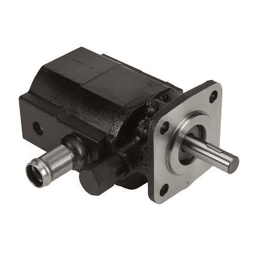
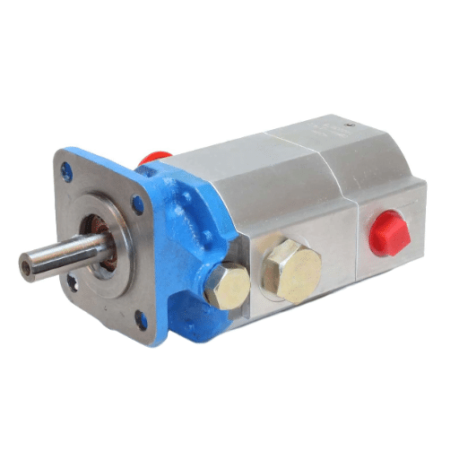
How does a gear pump function in a hydraulic system?
A gear pump operates in a hydraulic system using gears that mesh with each other, pumping the fluid via displacement. It is based on the concept of positive displacement, hence maintaining the flow rate even when pressure differs. In this case, as the gears rotate, the fluid enters the pump via the suction side. The fluid is enclosed in the cavities between the gear’s teeth and the pump housing. The rotating gears not only keep the fluid trapped between the gear’s teeth but also move it toward the discharge side where the fluid is pressurized and discharged.
- Flow Rate (Q): Typically ranges as per the size and the application of the pump while it is usually between 1-500 GPM (gallons per minute).
- Pressure Rating: For standard applications, it usually functions under a pressure of up to 3000 PSI (pounds per square inch), but for high-pressure systems, some models would exceed this.
- Efficiency: Volumetric efficiency tends to be around 85-90% when internal leakage and wear and tear over time takes place.
- Speed: The operating speed for gear pumps ranges from 500-4000 RPM, which allows for varied hydraulic systems. Thus, enabling them to be more flexible.
- Viscosity Range: Fluids having a viscosity of approximately 10-1000 cSt (centistokes) is where effective performance is maintained which provides the optimal conditions for lubrication and avoids excess friction.
These enable the efficient performance of gear pumps in a wide variety of configurations of hydraulic systems.
What are the advantages of using a vane pump?
- Efficient Vanes: Due to the narrow tolerances in the construction of the vanes and the cam ring, internal leakage is at a minimum enabling Vane pumps to fulfill tasks that require precise volumetric accuracy with high efficiency.
- Operating Pressure: Vane pumps are effective for use in medium-pressure hydraulic systems because they operate hervorragend at 100 to 200 bar of pressure depending on the model and design of the pump.
- Low Noise Levels: Vane-type pumps also outperform other pump types in regards to noise since the major design components are constructed in a balanced manner which reduces operating vibration and noise while maintaining a full rotational speed of up to 3000 RPM.
- Wide Range of Fluids: These versatile pumps are capable of efficiently pumping fluids with 10-300 cSt densities due to the highly variable fluid lubrication provided to the internal mechanical parts which reduces the frictional wear.
- Compact and Lightweight Design: Compared to other types of pumps, Vane Pumps are lightweight and compact, making them ideal for applications that have critical weight and space restrictions.
- Self-Priming Capability: Vane pumps are self-priming due to their reliable suction characteristics and are thus ideal for use in systems that operate under varied flow conditions and require intermittent operation.
These technical sequential advantages make vane pumps a preferred choice in industrial hydraulics, automotive power steering systems, and various fluid transfer applications.
How Does a Relief Valve Operate in Hydraulic Systems?

What role does a relief valve play in maintaining system pressure?
The relief valve is crucial to system pressure control because it mitigates the damage that excessive pressure could cause to system components or lead to an operational failure. One of its most important functions is to enable fluid to exit the tech system when the pressure surpasses a certain value, thus ensuring that the equipment remains operationally safe.
- Set pressure: This figure is usually pegged 10-20 percent above the standard operating pressure to avoid needless engagement but under the maximum allowable working pressure (MAWP) for safety reasons.
- Pressure Range: These components typically also have a predetermined minimum pressure and will not open if the pressure is below that minimum. This function can be crucial to the needs of hydraulic systems.
- Flow Rate Capacity: The discharge capability of the valve must equal or exceed the system flow rate to adequately relieve pressure spikes.
Relief valves, if installed and set properly ensure hydraulic systems precision and operational efficiency and longevity safeguard.
How to identify and troubleshoot a malfunctioning relief valve?
The first step I will take to make sure that the valve is working properly is ensuring that system behavior is consistent. Some symptoms of malfunctioning valves may include noises being significantly higher than their normal range, abnormal amounts of pressure in the system, or constant uplift in pressure. First, I would take a functional pressure gauge and compare the set pressure of the valve with the operational pressure of the system. If the valve seems to not be opening at the required level, that means there is ian nternal breakdown or the device is unsuitably calibrated. In addition to that, I would also carefully examine the valve for any obstruction that would make the valve malfunction.
- Verify Set Pressure: Examination of any cylinder in alignment with a specific device, for example, 2,500 PSI for hydraulic systems should be done.
- Inspect Internal Component: Check internal valves for washing, corrosion, and dirt. Internal components will have to be exchanged as well.
- Test Flow Rate: The valve should withstand the upper boundary of the system’s flow rate which may be grouped within the limits of 10-100 GPM depending on the scope of work application.
- Check Leakage: The usual method is examining the valve and adjacent connection to find any leaks when the device is working normally.
To fix the valve correctly, all the provided steps must be taken using the right tools to receive accurate results.
How Do Directional Control Valves Function?

What is the purpose of a directional control valve in hydraulics?
The objective of a directional control valve in hydraulics is to influence the movement of fluid in the hydraulic system. The start, stop and directional change of hydraulic liquid flow are regulated with the help of these valves. That allows the operation of actuators like motors or cylinders, making sure the whole system functions optimally.
- Port Configuration: Usually covers two, three, or four-way patterns depending on the application needs. A good example is a 4/3 valve that is often found in systems where two actuators need to be controlled with one of them in a neutral position.
- Operating Pressure: A requirement for every valve is to be within a certain range of pressures which can vary depending on whether it is an industrial or mobile hydraulic system, typically between 1500 PSI to 5000 PSI.
- Flow Rate Capability: The valves have to meet system flow rates, which are often set between 10-100 GPM, depending on the equipment’s operational needs.
- Spool Type: The spool configuration determines the fluid flow pattern for different states of operation of the valve.
The described characteristics allow the hydraulic systems to make use of the directional control valve by ensuring optimal flow and pressure for specific cases.
How does fluid flow get directed by directional control valves?
To give a summary of how the fluid flow is controlled by the directional control valves, the process is centered around the spool locations within the valve body. When the spool is shifted, specific flow paths are opened or closed, which in turn establishes the direction, starting, or stopping of the movement of hydraulic fluid. The spool position is usually controlled via manual levers, solenoids, hydraulic pilots, or mechanical linkages.
- Spool Positioning Mechanism: Controls how the spool is operated, e.g., with solenoid-actuated valves, precision electrical control is used, while in manual levers, there is less precision but more ease of operation.
- Flow Paths: The number and arrangement of ports in the valve define available flow paths, for instance, 4/3, and 3/2 configurations where distinct port and flow path availabilities are signified.
- Rated Pressure: The valve should manage system pressures, these can be as great as 1500 PSI to 5000 PSI in certain high-pressure systems to ensure operational safety.
- Flow Rate Capacity: By the design parameters of the hydraulic system, the valve is also expected to withstand the fluid flow rate of ten to one hundred gallons per minute.
Compliance with these technical specifications means that directional control valves have accurate fluid routing and maximum efficiency in the operation of the system.
How to Improve Volumetric Efficiency in Hydraulic Pumps?

What factors affect the volumetric efficiency of a hydraulic pump?
Here are some factors that affect the volumetric efficiency of a hydraulic pump:
- Internal Leakage: Too much movement between the parts of a pump may result in fluid loss due to bypass, which lowers efficiency. It is possible to reduce it by maintaining tight tolerances and using high-grade sealing materials.
- Fluid Viscosity: The working fluid’s viscosity level has a high-performance index. Fluids that have high viscosity result in significantly increased flow resistance, while low viscosity fluid leaks out easily. The normal recommended viscous range is approximately 16-36 cSt for hydraulic systems.
- Operating Temperature: An increased temperature can cause the breakdown of fluid properties, like its lubricating effectiveness, which results in lowered sealing and raised wear and tear. To combat this efficient cooling systems are important to keep the temperatures from exceeding 90 to 140 degrees Fahrenheit.
- Pump Speed: Turbulence, cavitation, and a drop in any degree of efficiency could occur if the pump is operated out of range i.e. 1200-3600 for most applications which is generally considered the danger zone. A manual check for the appropriate speed set by the manufacturer allows this information to be solved with ease.
- Component Wear: Parts such as pistons, cylinders, and valves get worn down over time which results in excessive space and lessened reliability. Regular inspections allow one to maintain a set level of operational stability while removing parts likethe BMP of CFD.
Controlling these elements and meeting the technical specifications of the hydraulic system makes it possible to maintain high volumetric efficiency and high equipment life.
How to optimize pump design for better volumetric efficiency?
To optimize the performance of the pump volumetrically, I would pay attention to reducing internal leakage, improving the precision of components, and ensuring proper adhesion to the system. Here are the basic technological aspects to consider:
- Seal Design: Using high-quality seals with low internal leakage permeability minimizes volumetric leakage thereby promoting volumetric efficiency. The seal design and materials selected should support the operational pressure and temperature.
- Clearance Tolerances: Narrow bypass gaps between components such as the pistons and cylinders guarantee unobstructed movement free from fluid bypassing while ensuring fluid flow. Here accuracy of machining is very important.
- Material Selection: Parts that contain strength-gaining elements are resistant to wear and thus maintain the accuracy of dimensions over time. For instance, hard alloy materials are best suited for high-stress situations.
- Pump Geometry: The geometry of the chambers of a pump should be constructed in a manner that the dead volume can be reduced to enhance the volumetric efficiency. Dead space results in insufficient working fluid elimination.
- Surface Finish: With internally polished surfaces, the reduction of friction and wear is further enhanced which increases fluid flow and reduces cavitation in parts of the pump that rotate faster.
These values can be incorporated into the design of the system volumetric efficiency optimization at the systemically hydraulic systems component, using such an approach assures the preservation of performance and reliability.
Frequently Asked Questions (FAQs)
Q: What is a hydraulic pump and how does it operate?
A: A hydraulic pump is a mechanical device used in hydraulic systems to convert mechanical power into hydraulic energy. It operates by creating a vacuum at the pump inlet, drawing liquid in from the inlet line to the pump, and then forcing it into the hydraulic system through the pump outlet.
Q: What are the types of hydraulic pumps available?
A: There are several types of hydraulic pumps, including fixed-displacement and variable-displacement pumps. Common types include axial piston pumps, radial piston pumps, rotary vane pumps, screw pumps, and positive-displacement pumps.
Q: How does a piston pump work in a hydraulic system?
A: A piston pump, such as an axial piston pump or radial piston pump, uses pistons to move fluid through a hydraulic system. The pistons reciprocate within a cylinder, allowing the pump to generate hydraulic power and move fluid efficiently.
Q: What is the difference between fixed-displacement and variable-displacement pumps?
A: Fixed-displacement pumps move a constant amount of fluid per cycle, while variable-displacement pumps can adjust the volume of fluid moved per cycle. This allows variable displacement pumps to offer more flexibility and efficiency in hydraulic systems.
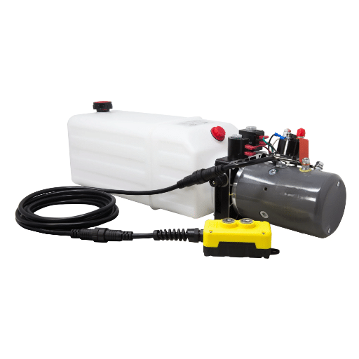
Q: How is hydraulic power used in industrial applications?
A: Hydraulic power is used in various industrial applications to perform tasks requiring high force and precise control. Hydraulic systems can power machinery, operate hydraulic cylinders, drive motors, and more, thanks to the efficient transfer of energy through hydraulic pumps.
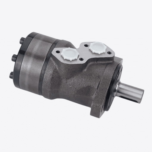
Q: What role does a hydraulic motor play in conjunction with hydraulic pumps?
A: A hydraulic motor converts hydraulic energy back into mechanical energy, allowing it to drive machinery or equipment. Hydraulic pumps and motors work together to circulate fluid and perform work in a hydraulic system.
Q: Why are rotary vane pumps used in hydraulic systems?
A: Rotary vane pumps are used in hydraulic systems for their ability to provide a smooth, pulsation-free flow. They are suitable for applications requiring moderate pressure and high reliability, making them popular in industrial and mobile applications.
Q: What is the significance of cutaway views in understanding hydraulic pumps?
A: Cutaway views of hydraulic pumps provide a schematic representation, allowing individuals to see the internal components and understand how the pump operates. This visual aid is essential for troubleshooting and maintenance.
Q: How does the pump output impact the overall hydraulic system?
A: The pump output determines the flow and pressure of the hydraulic fluid within the system. A properly sized pump ensures that the hydraulic system operates efficiently, delivering the necessary force to perform tasks while minimizing energy consumption.