A lot of industries rely on hydraulic systems to control various machines and tools using the right amount of force. Pressure relief valves are very important in these systems since they maintain the best pressure levels and shield the hydraulic components from any damage that surges in pressure could cause. About this, Bosch Rexroth’s DBW series of pilot-operated pressure relief valves can be regarded as a critical aspect within the hydraulic domain. These are known for their accuracy, dependability, and great strength; hence, they act as guardians of hydrostatic systems through which they regulate pressures, leading to smooth operational dynamics. This article focuses a bit on the technicalities of the DBW series, explaining their role in maintaining the integrity and efficiency of hydraulic systems.
What is a Bosch Rexroth DBW Series Pressure Relief Valve?

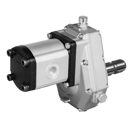
The Bosch Rexroth DBW series pressure relief valve is one type of pilot-operated valve designed specifically for hydraulic systems to relieve excess pressure automatically. It has a pilot valve that controls the main one so as to handle high flow rates and maintain precise pressure control. The DBW series is ruggedly constructed for durability and long-life operation even in harsh industrial environments. Designing it with adjustable pressure settings makes it possible to fit various system demands while enabling quick response during changes in pressure, thus avoiding overloading and damaging systems.
Key Characteristics of DBW Series Valves
Advanced technical parameters and robust construction characterize DBW series valves. Valve pressure settings may be adjusted between 30 and 350 bar; hence, they are used in various applications. Flow capacity is up to 400 liters per minute, so they can accommodate different operational requirements. Among them is their fast reaction to the peak pressures achieved through accurate pilot control; this feature avoids hydraulic shock risks or damage to systems. These valves are also made from quality materials that are resistant to corrosion, hence guaranteeing their durability in any environment that may be termed extreme, such as offshore installations with high concentrations of salt electrolyzing solutions. Hydraulic noise is also reduced by use of damping chambers so as to improve overall system stability.
Applications and Uses of Pressure Relief Valves
Pressure relief valves (PRVs) are integral parts in many industrial operations to ensure system safety and efficiency. They mainly regulate the pressure levels inside hydraulic systems thus preventing damage associated with surges in pressure. Examples include manufacturing industries where PRVs safeguard pumps, pipelines, vessels under pressure from bursting due to excessive content.
For instance, PRVs keep optimal power levels within an acceptable range, thereby avoiding overload in hydraulic power units. Hydraulic presses operate safely because these devices relieve excesses when they sense too much force being applied against them, causing harm to the machine itself and the workpiece. This flexibility and reliability across different systems depends on technical parameters such as adjustable pressure settings (30 bar to 350 bar) and flow capacity (up to 400 liters per minute).
Additionally, PRVs are vital in chemical processing industries as they prevent overpressure that may lead to leaks or ruptures in reactor vessels and pipelines. The fast response to changing pressures of these areas due to pilot control is important in managing high-risk situations such as process instabilities. Moreover, the valves in the DBW series are constructed using materials that resist corrosion and hence can be used even with high salt concentration, like the offshore installations with electrolyte solutions. This effectively increases their lifespan and performance reliability.
Kinds of DBW Pressure Relief Valves
Pilots exclusively operate DBW pressure relief valves to allow for accurate regulation of the system’s pressure. The pilot operation method aims to ensure stable and precise control over the system pressure, which prevents system overload and ensures safety. They usually comprise two main parts: the main and pilot valves. The pilot valve controls the pressure setting, opening under overpressure conditions to allow fluid to flow through the main valve, thus reducing system pressure to safe levels. Such design becomes more advantageous, especially in high-pressure and high-flow applications, making DBW valves applicable across different industrial sites. These valves are characterized by such qualities as adjustable pressure ranges, capacities for high flow rates as well as strong materials in construction that can stand up to tough operating environments most often associated with them.
How Does a Pressure Relief Valve DBW Work?

Understanding how a DBW pressure relief valve is carried out involves the balance of complexity between the pilot valve and the main valve. When the system pressure is within the normal operating range, the pilot valve remains closed, and a spring or other mechanism shuts the main valve. If it approaches its set point and the system pressure is rising, the opening of one pilot valve, which in turn leads to exceeding system pressure on the main valve seat by reducing control of fluid flow over its piston. Consequently, excess pressure causes the main to open, thus protecting it from over-pressurization. Once again when pressure normalizes, then eventually closing pilot valves close while returning to their former positions also seal off flow across them. This delicate operation ensures that system pressures are always within safe limits.
Internal Mechanics and Operation
Several critical components comprise a DBW pressure relief valve. These are the pilot valve, the main valve, the spring mechanism, and various seals which ensure fluid integrity. Detection of specific pressure thresholds is dependent on finely tuned pilot valves. When these occur, they open allowing some amount of fluid to pass through an aperture smaller than usual thereby bringing down the pressure in the main valve.
The main valve is usually a piston or diaphragm that responds to changes caused by pilot valve actions. When it opens, it allows the main valve to operate by reducing pressure on its piston, thereby discharging excess fluids out of it, resulting in reduced system pressures. Under normal operating conditions, the spring mechanism is responsible for keeping the main valve closed, compressing upon activation of the pilot valve.
Important technical details include adjustable pressure ranges ranging from 10psi up to over 6000psi catering for industrial uses. Another important parameter is flow capacity; this determines how much liquid can be allowed out and is often expressed as gallons per minute (GPM) or liters per minute (LPM). These materials, such as high-grade alloys or stainless steel, are chosen because they have long life spans and are not corroded easily, even when used in harsh conditions. Those specifications ensure that DBW pressure relief value performs effectively within the safety limits designed.
Pilot Control Valve Functions
In hydraulic systems, pilot control valves perform vital functions while controlling flow direction and rates of fluids, leading to optimal machine performance. These valves work on differential pressures created between inlet and outlet points. Consequently, this modulation causes overall fluid flow within the system by actuating its other flow controllers.
Material construction, flow rate, and pressure range are among key technical parameters describing pilot control valves. Pilot control types have adjustable upper limits exceeding 6000 psi to accommodate different industrial needs, starting from lower limits like 10 psi. Quantitatively, flow rates are reported in gallons per minute (GPM) or liters per minute (LPM), which vary depending on valve size and application requirements.
Pilot control valves are very important because they can be made from stainless steel, brass, and high-grade alloys. These materials are chosen based on their durability and corrosion resistance properties, which ensure that the valves serve for longer periods without any problems. They also comprise sealing elements such as EPDM or Viton elastomers to ensure compatibility with various fluids.
To summarize, pilot control valve functions include precise modulation and dependable control over fluid management systems hinged upon pressure handling capabilities, flow capacity, and material durability. These technical parameters provide a basis for choosing an appropriate valve to effectively and safely meet particular operational requirements.
Unloading Function and Pressure Control
To sustain system efficiency, the unloading function in pressure control systems is designed to divert excess fluid when the required pressure is achieved. For this purpose, it mostly involves a pressure relief valve or an unloading valve dedicated to forcing the flow of liquid back into either the reservoir or intake side of a pump as it avoids over-pressurization and possible damage. Valve activation is determined by preset pressure settings that enable automatic engagement and disengagement to keep an optimal level of tension. The unloading process reduces energy consumption, which helps enhance a system’s overall performance and reliability because it minimizes the workload on pumps & motors; consequently, components such as these have a longer life span.
What Are the Key Specifications of a Pressure Relief Valve DBW?

A DBW Pressure Relief Valve has several key specifications ensuring the best pressure control systems performance. First, the valve’s range within which it can be set determines its ability to keep the system functioning at a given range of pressures, normally wide enough to fit different operational requirements. The flow rate capacity is expressed in GPM (gallons per minute) or L/min (liters per minute), representing the fluid that can move through the valve without any setbacks. Another important aspect is material composition, which often includes corrosion-resistant solid alloys such as stainless steel or carbon steel for increased durability and reliability under varying conditions. Moreover, the temperature tolerance of valves also plays an important role since it specifies both upper and lower temperature limits for ensuring steady operation despite changes related to environmental heat levels. Lastly, pressure relief valves are usually equipped with adjustable pressure settings and built-in safety devices that prevent accidental over-pressurization, protecting systems from damage while maintaining efficiency.
Discharge Line Pressure
Discharge line pressure in hydraulic systems requires accurate monitoring and control for efficient operation and safety. High discharge pressures may indicate flow restrictions or obstructions within a hydraulic system resulting in increased power consumption and possible damage to components within the system. On the contrary, low discharge pressures could signal leaks, poor pump performance or incorrect valve settings. Efficient management of discharge pressure means using pressure-safe valves to redirect excessive pressures, utilizing pressure sensors for continuous performance monitoring, and conducting regular maintenance to promptly identify any potential problems. To maintain system dependability and prevent equipment failure while achieving desired levels of operating efficiency optimum discharge pressure must be kept.
Reverse Pressure on Discharge
Reverse pressure on discharge line acts as an impedance mechanism affecting overall system efficiency and performance. It is defined as a residual closing head existing after fluid leaves the pump in a closed line environment, caused by the length of pipeline diameter and other elements present within skid systems leading to counter pressure. Failure to manage counter pressure may result into substantial energy losses and damage to system components. Reducing unnecessary back pressure can be done by optimizing pipe diameter, minimizing bends and fittings, and installing properly sized discharge filters, among other techniques. Well-calibrated pressure regulators and relief valves also help control back pressure when maintaining a smooth and efficient hydraulic system.
How Do You Set the Relief Pressure on a DBW Valve?

Setting up the relief pressure in a DBW valve involves several steps. First, ensure that the system has been depressurized and safety has been taken care of. Look for an adjustment screw or knob on the DBW valve, which is typically hidden beneath a protective cap. Monitor the system pressure using a pressure gauge. While making adjustments keep an eye on the pressure readings in the gauge located there as you turn this screw clockwise to increase or counterclockwise to reduce it. Make small adjustments, incrementally increasing the desired target pressure and allowing stabilization before proceeding further. Then secure the setting by replacing any protective covers and re-pressuring the system again to verify its settings accurately on relief pressure. Regular testing and calibration are recommended to be sure that the performance of the DBW valve remains within specified parameters.
Adjusting to the Lowest Adjustable Pressure
To adjust to the lowest adjustable pressure, one must follow a systematic process ensuring precision and safety aspects are adhered upon during setup of a DBW valve. It is important at first to ascertain if hydraulic systems have been fully de-pressurized and all precautionary measures have been appropriately observed. Located under a safety cap is usually an adjusting screw or knob that can be identified with ease on such valves as DBWs. Turn slowly in the counter direction using increments while fitting. There is no need for additional explanation since it is obvious which very slow adjustment will work well with this case because it requires fine-tuning towards minimum levels (pressure setting). Observe continuously this meter against reducing pressures to make certain.
Lowest adjustable pressures will occur once we are done turning it by just some degrees; hence these values can be achieved by screwing down our set points until they almost touch any hard stop limit provided for them so as soon as they do – leak will begin through them from underneath even though truest bottom lines toward them might end up being perfect which shall only differ by a couple hundreds’ maybe even tens’ steps.
Process of Setting Response Pressure
Setting the response pressure involves carefully planned steps to ensure peak accuracy and system performance. Begin by thoroughly depressurizing the system and adhering to all relevant safety protocols. Locate the response pressure adjustment mechanism, typically an adjustment screw or knob situated beneath a protective cap. Attach a calibrated pressure gauge to the hydraulic system to monitor the changes accurately. To increase the response pressure, turn clockwise in increments; rotate counterclockwise to decrease it.
As you make adjustments, constantly monitor the pressure readings on the gauge. Allow the system to stabilize after each small adjustment to ensure accurate readings. Continue this process until the desired response pressure is achieved. For example, if setting a DBW valve to a specific response pressure of 2500 psi (pounds per square inch), ensure that each incremental adjustment is controlled and that the pressure gauge confirms reaching this value accurately.
After adjusting the response pressure, replace any protective covers on the adjustment mechanisms. Then, carefully dress the system organized before gradually re-pressurizing it. During routine maintenance checks, not only identify any deviations but also meticulously record them in writing, ideally in a free-form manner. It is advisable to document these settings in the device’s log for future reference in repair or replacement tasks.
What should be Done in Case of Power Failure or Cable Break
It is important to take a systematic approach in case of a power failure or cable break, which can minimize downtime and enhance safety. Firstly, establish the immediate functional status of the equipment and note any critical implications. In the event of a power failure, determine whether the problem is localized or widespread by checking circuit breakers, fuses, and the supply source. Ensure all employees are informed about what is happening on site and follow safety procedures, including switching off machinery where necessary.
The affected section is isolated by disconnecting power to avoid electrical accidents due to cable breaks. Visible damage should be checked on cables, and if necessary, temporary measures like using alternate sources of energy or standby generators may be applied for essential operations only. Try to find out why it happened; if it was caused by environmental factors, wear and tear, or external forces, for example. After establishing its location, replace/repair such damaged cables according to the manufacturer’s guidelines and industry norms.
Upon fixing this issue gradually restore back both power availability as well as overall system functionality so that circuits do not get overloaded. Conduct an extensive test to ensure that all systems are functioning properly and repaired cables have met safety standards. Write down what happened, including causes, steps taken to fix it, and prevention strategies used to improve future response plans. Engaging in regular maintenance activities and routine inspections is always advisable to minimize the chances of such incidences occurring again.
What Are the Safety Features of Bosch Rexroth DBW Valves?

Bosch Rexroth’s DBW valves are equipped with several safety features that ensure reliable and safe operation. These valves possess inherent pressure-limiting functions to avoid excessive pressure build-up that may cause damage or personnel injury. Furthermore, they have a strong ability to reset themselves in the event of power loss or system failure through a robust fail-safe mechanism. The DBW valves also provide an advanced level of monitoring that enables users to recognize any abnormality away from normal working conditions. Against this backdrop, they have long been able to maintain steady performance levels and are more secure in varied hydraulic applications.
Type Examination Tested Safety Valve
Type examination-tested safety valves are widely used for industrial purposes and undergo intensive testing to ensure compliance with strict safety and performance standards. For these safety devices to be subjected to type-examination approval processes, their designs, materials used in making them, way of construction and functional features must be appraised by a recognized body about its risk category as well as other criteria such as pressure, volume, temperature and nature of medium contents within the equipment. This is done specifically to verify whether these devices can safely serve their intended purpose under expected working conditions comprising such factors like capability for relieving overpressure cases properly, restoring itself into safe condition after being activated as well as fulfilling mechanical durability requirements during its operational life span. By satisfying these criteria, type-examination-tested safety valves play an important role in mitigating overpressure hazards, thereby enhancing overall system integrity and operator protection. Periodic inspections and servicing according to manufacturer’s recommendations are essential for maintaining the reliability and efficiency of these safeguards.
Complying with the Pressure Equipment Directive
The Pressure Equipment Directive (PED) 2014/68/EU makes sure that all important safety requirements regarding design/manufacture/conformity assessment of pressure equipment within the European Union are met accordingly by establishing regulations on it. PED compliance involves choosing the relevant conformity assessment module based on the hazard category of equipment, which depends upon factors such as pressure, volume, temperature and nature of media. Manufacturers are expected to prepare a technical file that includes design calculations, risk assessments and detailed drawings. A Notified Body then examines this file through audit inspections and tests to establish its compliance with the PED. Furthermore, manufacturers have to mark their products with CE and sign declarations about conformity to the requirements of this directive. The process renewed by periodic checks, inspections and tests carried out according to standard manufacturing practice guarantees the maintenance of conformity.
Technical Data and Deviations
Pressure equipment’s technical data typically includes parameters such as maximum allowable pressure (PS), minimum/maximum allowable temperature (TS), volume (V) and material properties. Technical deviations occur when particular machinery fails to meet such criteria during its design, manufacturing, or operation stages. The common deviations include, e.g., variation in material composition, dimensional inaccuracies, or those arising from test results mismatching standard needs. For this discrepancy to be addressed adequately, a careful analysis must be conducted to evaluate how it affects the performance and safety of the unit itself. These measures may involve redesigns or other corrective actions like additional testing and improved inspection processes, among others, since they have been required to ensure that a given piece meets all applicable safety requirements before being certified compliant with PED standards on its performance test results alone.
Why Choose Bosch Rexroth Pressure Relief Valves?

Bosch Rexroth pressure relief valves are designed to ensure excellent reliability and performance in tough industrial conditions. Their great construction guarantees durability for the long term and smooth running even under different environmental circumstances. The valves have new features that improve accuracy in maintaining system pressure, reducing wearing out and cutting such expenses as maintenance costs. Besides, Bosch Rexroth also provides a wide range of pressure relief solutions meeting high safety standards so that users can be confident that their systems are safe from excess buildup of pressure. At the same time, there is an option for making changes to suit integration with other existing systems, guaranteeing optimum performance and compliance with safety requirements.
Advantages of Bosch Rexroth DBW Valves
In complex hydraulic systems, Bosch Rexroth DBW valves are notable for their precise control and rugged construction. They have a great advantage because of advanced pressure adjustment, which helps to meet exact requirements, enhancing efficiency and productivity, respectively. Furthermore, these valves include an integrated check valve that prevents reverse flow; thus, it safeguards the system against possible surges or drops in pressure.
More specifically, the DBW valves have a broad-ranging 30-350 bar field of adjustment pressures suitable for many diverse industry sectors. Response times combined with flow rate capacity are arranged such that they offer system stability, thereby ensuring proper functioning without any hitches at all under optimal situations where a maximum of 400 L/min can be directed through them. Moreover, the robustness of the DBW series, which consists of top-quality materials like corrosion-resistant coverings, means that they will still work reliably over short intervals.
Additionally, Bosch Rexroth DBW valves are easy to maintain and integrate because of modular components which facilitate quick spare parts replacement or upgrading the whole system within no time hence minimizing downtime resulting from machine break-downs. They are also certified by international safety authorities, ISO9001/ISO14001, further affirming their dependability and quality. They can be modified per specific system needs, making them versatile and useful in different industries.
Precise Pressure Control and Reliability
The exactitude of Bosch Rexroth DBW valves is achieved through a combination of mechanical and electronic control techniques for pressure adjustment. Parker Hannifin, Eaton, and the official Bosch Rexroth website, among others, found this valve to have proportional control as it varies hydraulic pressure according to varying demand conditions. Furthermore, the position of the valve is adjusted continuously by the electronic control unit, which monitors the pressure levels under all conditions in the system, thus maintaining an even operating performance throughout. The advanced engineering systems used on DBW valves have very low drift rates. They are designed to provide robust protection against spikes in hydraulic pressure, ensuring consistent operation under changing load conditions. This type of precise pressure management is needed to maintain the proper functionality required for complex industrial procedures while optimizing the efficiency or lifespan of hydraulic systems.
Where to Buy Bosch Rexroth Industrial Parts
Several well-known online platforms sell Bosch Rexroth industrial parts. An extensive catalogue can be found on its official website, where customers can order directly from them instead of struggling with counterfeit products. Other distributors, such as hydraulicpump-suppliers, offer large stock reserves, reasonable price levels, and dependable delivery options for buying these items within limited periods. Moreover, these sites are also useful in terms of guidance since they provide technical support whenever one requires it and detailed information regarding their product lines that may aid in choosing appropriate supplies for one’s project needs.
Reference sources
- Bosch Rexroth Official Website
- Source: Bosch Rexroth
- Summary: The Bosch Rexroth website provides detailed technical documentation on their DBW series pilot-operated pressure relief valves, including specifications such as component series, pressure adjustment ranges, and operational features.
- Kanflu PDF Resource
- Source: Kanflu
- Summary: This PDF document offers comprehensive insights into the design and functionality of the DB and DBW series pressure relief valves, highlighting installation guidelines, operational mechanisms, and performance metrics.
- Hydrotech Online Shop
- Source: Hydrotech
- Summary: Hydrotech’s online shop provides a detailed product description for the DBW series pressure relief valve, focusing on its application in limiting and solenoid-actuated unloading of operating pressure, alongside technical details about pressure adjustment and maximum operating conditions.
Related Articles: Bosch Rexroth Pressure Relief Valve Catalog