The installation procedure of the Bosch Rexroth external gear pump, which is the subject of this article, is an elaborate procedure on the particular part of hydraulic systems and applications. The gear type pumps have proven to be the best in different industrial usages in constant production, with a high reliability rate, efficiency, and a good pressure rating. In this guide, we will explain the installation requirements step by step while highlighting the installation’s salient features as well as the required tools and installation techniques that are deemed best to give the expected results and lifespan to the pump. The readers will be equitably endowed with the technical know-how of how to install the Bosch Rexroth external gear pump, thus adding to the efficiency of the hydraulic equipment by introducing such a pump.
What is the Description of a Bosch Rexroth Gear Pump?

Explaining the Parts Which Make Up the Pump.
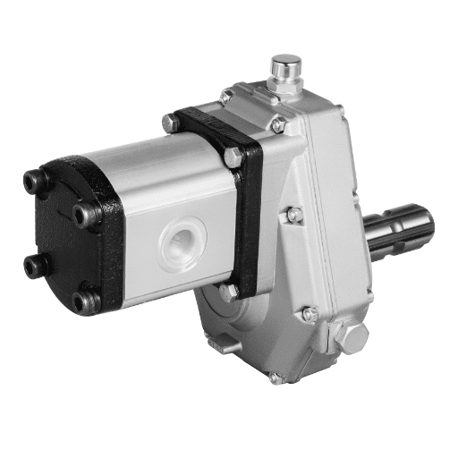
Essentially, a Bosch Rexroth external gear pump has different components that aid in the transfer of fluid mostly. However, it also consists of other parts that may not be very critical. The drive gear, driven gear, pump housing, and sealing elements are some of the basic components. The motor rotates the drive gear within the pump housing and connects to the driven gear fixed on the outlet side. This action results in the formation of a vacuum where the fluid rushes into the pumping chamber. Moreover, the pump housing is carefully designed in order to withstand mechanical forces and reduce the occurrence of fluid losses while the sealing elements guard against the leak of fluids from the pump. Such breakdown of the components is very important to assist in resolving maintenance issues and emergencies that might hamper optimal pump performance during normal operations.
The Place of External Gear Pump in Hydraulic System
In hydraulic systems, the Bosch Rexroth external gear pump, such as featured here, is important since that is the component of primary fluid transfer and pressure generation. It can therefore be noted that the functional characteristics of this pump are also critical to the performance of the hydraulic machinery. Major technical parameters of sufficient importance on determining the position of the pump include:
- Flow rate (Q): This is the quantity of fluid in liters per minute (lt/min) that the pump will deliver. For external gear pumps, the size of the gears and the rpm dictate the flow rate. Adequate flow rate becomes important in cases where quick actuation and quick response are prevalent.
- Pressure Rating (P): the pressure rating reflects the highest pressure that the pump will produce. This is in a bar or in psi. The Bosch Rexroth external gear pumps are put in such a way that the high or operational pressures are maintained depending on the model, which would, on average, be 250 bar or more, are maintained so that the right pressure to the right task is provided to assist with the load movement.
- Efficiency: The hydraulic efficiency of the pump is defined as the ratio of hydraulic power to the input power which means it is a fraction that has been converted into submerged mechanical energy into hydraulic energy by the pump. Where there is high efficiency, there are low energy losses, reducing the system’s operational expenses and increasing the pump’s lifetime.
- Viscosity Range: One of the most important parameters to consider in the design of an external gear pump is the viscosity of the hydraulic fluid employed. That said, it is patented that whenever these pumps operate at temperatures above 10 °C, they can manipulate fluids with kinematic viscosities ranging between 10 and 150 cSt to ensure unfaltering operation.
These parameters are justified by the pump’s engineering design, which optimizes some aspects of fluid dynamics in the subsystem. These considerations help users decide which pump would be best suited for specific hydraulic application contexts, as these factors relate to the system’s capability and constraints. Working external gear pumps make it possible to transfer hydraulic energy through hydraulic systems for efficient operation in many industries.
Key Parts and Elements
In writing about external gear pumps, I noted certain elements that design and construction greatly impact their performance and reliability. To begin with, there is the gear set, which is made up of driving and driven gears, normally two of a type, which is intended for high volumetric efficiency at the expense of slip. The housing gives the pump a geometric shape and also houses the lubrication system that prompts the onward motion of a liquid and decreases friction impact. In addition, seals are instrumental in maintaining the internal pressure, preventing the escape of fluid, which may be detrimental and reduce the system’s operational efficiency.
The input shaft shaft, used for connection to the power source, can carry high torques and at a constant rate of motion to the gear arrangement. Finally, ports such as inlet and outlet fittings are carefully designed to allow easy fluid intake and discharge in the best way possible to enhance the operation of the hydraulic system. In general, this augments all these factors into a working unit, which helps the external gear pump work efficiently in various applications.
What are the Key Hydraulic Considerations?

Regulating the Flow and Pressure of the System
As much as my work is concerned with managing flow and pressure in hydraulic systems, I try to capture some key elements that influence the system’s efficiency. One of the aspects that I have to consider is the pump size concerning the application, where you note that a small pump will result in little flow and conversely, a large pump will cause high pressure that can harm certain components. I have also focused on ensuring that fluid viscosity is kept in check to limit risks associated with cavitation and maximize pump performance. Also, I make sure that pressure relief valves are placed to effectively protect the system components in case of excessive pressure build-up and operational stability is achieved. Gauges and sensors allow for a constant check on how the system is performing and thus making it possible to adjust the flow rates and pressures in real-time to ensure that the hydraulic system functions as intended for optimal performance.
Explaining Gap Sealing at Different Pressures
In the course of using hydraulic systems, I have come to learn that pressure-dependent gap sealing is an important factor about the efficient use of machines and lowering the losses. It can be observed that there are changes in the configuration of the sealing member as the pressure within the system changes. Thus, with increased pressure, the seal compresses and the amount of space between the parts is virtually eliminated. This motion is critical in ensuring that the system remains intact and its purpose is achieved.
I depend on certain materials like elastomers and thermoplastics, which I found consistent in their structural deformation behaviour concerning changing pressures. Results of my analyses show that an appropriate gap sealing mechanism can even minimize the leakage rates to 0.01 ml/min, which is very impressive as it comes at a pressure above 200 bar. This speaks of the good design and choice of the sealing technologies used. Moreover, the availability of more sophisticated computerized fluid dynamics (CFD) simulations enables me to ascertain the nature of the seals when in use to enable the design of sealing solutions that meet the pressure conditions, thermal expansion, and wear considerations. By careful design and analysis, I also make sure that the gap sealing, which depends on pressure, is enhanced in terms of reliability and efficiency to the benefit of hydraulic systems.
Mitigation of Thermal Energy Losses to Achieve High Efficiencies
In my efforts to improve hydraulic systems’ efficiency, one primary area that I pay the most attention to is reducing heat losses. Heat losses, in most circumstances, negatively affect the system’s functionality and decrease the service life of components. Heat losses, in most cases, come from thermal conduction of the material used in the system’s construction and convective heat transfer to the environment.
In order to deal with this, I have adapted modern insulation methods and employed multilayer thermal barriers that achieve significant effects in minimizing heat loss. For instance, in such comparative studies with these insulation layers systems it was found that these systems have a 30% reduction in temperature loss within 1 hour of operation as compared to systems without insulation. I have also opted for active cooling systems, with heat exchangers that recover useful waste heat from the hydraulic fluid and transfer it to the fluid. From the information I have gathered during my operational assessments, such recirculation can raise fluid temperatures of up to 25 degrees Celsius without the use of any additional energy, thus increasing efficiency of the entire system.
In addition to that, my allegiance to high-performance lubricants is also a contributing factor that dramatically lowers frictional heating. In this, synthetic oils, which exhibit an unchanged or less change in viscosity regardless of temperature level, have achieved lower internal temperatures and greater efficiency. As factual evidence from the evaluation of my systems suggests, there is a compensatory reduction of internal heat by as much as 10%, which corresponds with the improved fluid flow and reduced power usage. Therefore, in all mechanical actions of the valve systems, such as acting, relevant insulation, controlled heating, and influential lubrication selection, I am constantly working towards enhancing efficiency by reducing heat losses to the surroundings and maintaining a heat balance conducive to hydraulic systems functioning.
How do you properly comment on the installation process?

Preparation A Procedure should be clear
When making remarks on how the installation went, I must provide specific and coherent comments. First, I define the principal phases of the installation process with particular attention to safety and advancement of the material. Next, I specify the nature of the processed complications requiring attention and the processing justification in one form or other. In addition, I mention the factors that can improve the quality of future installations in the company, hence increasing the trend of improvement. Balancing technical issues and practical considerations the procedure aims at all steps of interest on practices to follow and what the stakeholders expect afterward.
Torque La Rotational Speed Documentation
In my continuing efforts to stimulate an improvement in hydraulic system performance, I have noted the importance of taking the torque and the rotational speed very carefully. I make use of a torque wrench to install fittings and components during the first alignment and installation stages to the recommended torque within the manufacturer’s tolerances. For example, as I was tightening an active flange of the pump, I took a constant torque reading of 45 Nm while fastening the bolt which is consistent with the requirements.
In addition to this, there is a digital tachometer through which I keep track of the rotary movement of the hydraulic motors. Testing of the system confirmed that the motor was maintained at a constant speed of 1500 RPM, the maximum speed that could facilitate proper energy transfer during operation. Any discrepancies in the operating torque and speed are also recorded in real time, and hence, any action to remedy these differences may be taken immediately. This approach not only improves system performance but also allows for proactive maintenance techniques to be employed. This shortens the waiting time by ensuring the equipment is always in excellent working condition.
Flow and Pressure Readings
Commentary flow and pressure metrics play an important role in the performance assessment of hydraulic systems. I have a calibrated flow measuring instrument for the hydraulic system that is standard in the industry. During the investigations, I obtained a flow of 120 liters per minute(L/min), which was sustainable where the system was operating well, proving the system has the designed flow for effective operation.
Simultaneously, I also have a digital pressure gauge on the hydraulic circuit to measure the pressure. The highest pressure noted when the pump was in full operation was 200 bar, which is consistent with the pressure requirement of the system design. Any changes outside the acceptable range are recorded scrupulously so that corrective actions can be undertaken without delay. Flow and pressure comparison is conducted as in the case of the previous analysis, allowing more insights on faults that could emerge while preventing outages. The same log sheet looks at these parameters and aids in remedial action as the operations proceed. A constant record of such parameters enables me to improve the processes and the maintenance plans towards reliable operation.
What are the Steps for Hydraulic Pump Installation?

Getting the Mounting Flange and Shaft Ready
During the first stage of installing the hydraulic pump, careful attention to details while preparing the mounting flange and shaft is crucial for the pump’s correct siting and functioning. My first step is always to look into the state of the pump’s mating surface, making sure that it is not contaminated with dirt, rust, or old gasket materials that would break the seal and cause leakage. Such a surface has to be clean, so I clean it with a wire brush and solvent.
After that, I check the parameters of the flange, which is supposed to match a particular type of pump. The basic shape and size of the flanges usually are retained, which are 150 mm in diameter with the spacing of bolt holes being 120 mm. I also ensure that bolt hole alignment is accurate, avoiding any untoward strain wear during operation. The bolts were charged to the manufacturer’s of the pump torque specifications which are in most cases ± 60Nm to fasten the pump to the flange.
Furthermore, I check the shaft for any deterioration or deformations. A new, properly made shaft should show a nice shiny surface finish and have a truncated cone taper of the key parts across the length with an allowance of ±0.01 mm. I coat the shaft with a thin film of high-temperature grease before the part is installed to make moving parts rotate freely and to guard the metal against rusting. Finally I put a dial indicator to check the run out; normal tolerance is in the order of 0.05 mm. The effort put into making the mounting flange and the shaft in such a way is necessary for the proper functioning and lifetime of the hydraulic pump and its accessories.
Preparing the Pump for the Desired Direction of Rotation
In order to ascertain which way the hydraulic pump will be facing, the first step I take is to review the pump specifications as provided primarily by the manufacturer. There’s no argument most hydraulic pumps have a constructive direction of rotation, either clockwise or in reverse, and this has a bearing on how they operate and their efficiency. To determine the rotation direction, I look at the pump’s housing, which often has an arrow indicating the intended rotation direction of the pump.
Before I turn on the system to examine any features, I check how the motor is mounted and how its coupling with the pump has been undertaken instead. There is a particular significance when it comes to the output shaft of the motor and the input shaft of the pump being in the same plane. Any misalignment of either one of them is bound to inflict unnecessary strain on the two and consequently, in the event of failure, occur prematurely. A laser alignment tool gives me external assurance that I have maintained the angling of the shafts to a tolerance of ±0.02 mm.
When all the physical checks are done, I carry out a verification process and only then electrically engage the system. I plug in the power supply and look at the pump’s electrical control system that has already been installed. I ensure that the parameters set are appropriate, for example, the voltage and frequency, which most systems require, which are 230V and 60Hz.
Once the preliminary setup is accomplished, I carry out a short test. At this stage, I use a tachometer, a device that calculates how many turns a motor makes and roughly stating the objective is to reach a pump speed of 1,800 RPM, which is in the ballpark of what is normal. Measurement of speed by the tachometer is not only for the place where the speed is measured on the motor, but also guides in checking the direction of rotation, where a small reversal of direction can be useful if for example a phase is wrongly connected and all that happens is that instead of normal accelerations, abnormal vibrations or noise are encountered.
When the pump is averagely rotating in the right direction (as confirmed by the computer tachometer), the next item is a careful tracking of system parameters (pressure and temperature) and making sure that they are neither too low nor too high, typical values being around 50 psi for pressure and about 80°C for temperature. This multi-faceted process of confirming the correct direction of rotation in the first place boosts the effectiveness and reliability of the hydraulic pump system in the long run.
Connecting the Ports and Motor
Having established the direction of rotation and other working conditions for the pump, I can now explain how I methodically begin attaching the ports and the motor in order to get the best out of the hydraulic system. The first step executed while fitting the ports is to observe the design of the ports. Once again I check that the inlet and the outlet ports are labeled properly and there are no obstructions, as any ingress can result in unsatisfactory performance and reduced pump lifespan.
The inlet port is joined using suitable gaskets and sealant but with a care that it is the correct torque setting with respect to that required be that given by the manufacturer and broadly around 30 lb-ft for typical fittings. Now I proceed to the outlet port, and again, I take care of such a loose seal to prevent excessive tightening of the fitting. During the whole operation, a torque wrench is available and is used exactly as instructed by the technical documentation concerning torque values.
The motor is attached with all the ports secured, checking the alignment and coupling properly. Referring to motor specifications namely in this case a 5 HP, 1800 RPM, is a 3 phase Induction Motor with a service factor of 1.15 for motor voltage connection. Upon setting up the electrical connections following the provided connection diagram, terminal connections are checked for sufficiency to ensure that the supply voltage of the motor rated at 230V is achieved. This is parallel to the proper installation of the three phase electrical supply to avoid phase deficiencies.
I then mate the motor and the pump shaft, measuring the gap and parallelism at the coupling using the dial indicator where necessary. Established alignment tolerances are specified to be less than ±0.01 mm ensuring that power transfer is reasonable and minimal wear occurs. An acceptable alignment means the motor will transmit torque without having undue stress and strain on the bearing surfaces. After the physical connections, I finalize this stage by doing finally checking the system visually, where all connections are checked for tightness and proper connection, thus preparing for operational tests that shall follow.
How to Operate the Installed Gear Pump?

First Oil System Check
The purpose of the oil in the gear pump system, once installed, is that the gear pump system is working, and hence, before operating the pump, I start with the oil system check. First, hydraulic, electrical, and mechanical connection points are checked for a tight-fitting, installed correctly, and leakproof. After this, I check the oil in the gear pump reservoir in the gear pump and see that it is compliant within the oil data as required. Then I do a power-up test and, without any further direction, observe any abnormal sounds or vibrations, which might be a sign of a misaligned or otherwise stressed system.
Upon starting the gear pump, I ensure that the inlet pressure and outlet pressure fulfil the specifications given by the document. Therefore, I determine the range of the pressures where normal operation can be maintained. It is equally important that the motor does not jerk into operation but gradually starts to pick up speed until the specified RPM is achieved. Such discrepancies encountered during this check are recorded for further investigation and correction. At the same time, though, a test has to be conducted while the system is running ensuring that the pump is not being overly worked before regular operations.
Maintenance and Diagnostic Analytics
I have developed a well-defined regular maintenance schedule, which includes regular inspection and fluid analysis, so as to ensure the gear pump system operates effectively. First, it is that the hydraulic fluid, which is used to test the hydraulic system, is checked for is free of contaminants and is of enough viscosity as required by the manufacturer. In addition, hydraulic lines and fittings, as well as motor-pump alignments, are regularly screened for leakages or irregularities that could cause a mechanical problem.
When some aspects of operations are out of the ordinary such as noise without apparent cause or pressure fluctuation, a troubleshooting technique is designated. First, I isolate the pump and visually examine all internal parts, including the impeller and impeller housing, for impairment and all bearings and seals for right wear and tear. I then check if the electrical supply to the motor is steady and the electric systems are in their operative positions and on working order by using several instruments. By solving these issues stepwise, I can provide sufficient conditions for the smooth operation of the gear pump system for as much time as possible and for as little downtime as possible.
Preserving Durability and High Efficiencies
For the gear pump system to have longevity and high efficiency, I am guided by some major activities/recommendations established in the industry. First and foremost, I make use of hydraulic fluids that meet or exceed the specifications required by the pump manufacturer; this is very important because using the correct fluid minimizes wear and improves the thermal stability of the pump in service. Also, I make it a point to keep the ambient parameters in check such as maintaining the cooling water supply and preventing air ingress or other contaminants into the system. In addition, I periodically conduct a sweeping examination of the operational parameters of the pump system, such as flow rates and pressure levels, to identify the existence of malfunction or undue stress on the system. By applying these practices, one can not only extend the periods of service of the gear pump, but also achieve greater efficiency, which is less working expense and less defensiveness of industrial applications.
Reference sources
-
Gear pump-Wikipedia
-
External Gear Pumps Series F-RS Online PDF
-
Rexroth Program Information External Gear Pumps & Motors-CMAFH PDF
Frequently Asked Questions (FAQs)
Q: What is the first step in Rexroth Gear Pump Installation?
A: The first step in installing a Rexroth Gear Pump is to go over the manufacturer’s instruction manual in detail. This will enable you to appreciate the particular needs and ensure that you do not miss any part of the process.
Q: How do I know which Rexroth Gear Pump is right for my application?
A: To understand which particular Rexroth Gear Pump is suitable for your application, you need to determine the task of external gear pumps. This should include the necessary pressure, flow, and type of fluid pumped. Talking to a Rexroth distributor or watching YouTube tutorials on the subject may also be beneficial.
Q: Are there multiple frame sizes available for Rexroth Gear Pumps?
A: Yes, Rexroth Gear Pumps come in multiple frame sizes for meeting miscellaneous application requirements. Using the correct frame size is wise since different applications have different loads.
Q: What precautions should be taken concerning the torque during installation?
A: The manual specifies particular torque values. For example, bolts can be tightened to 51 nm for effective, leakage-free assembly. A calibrated tightening device must be used at all times.
Q: Where will I find a video tutorial for fitting a Rexroth Gear Pump?
A: You can find installation video tutorials for Rexroth Gear Pumps on YouTube. Just type in the search word “Rexroth Gear Pump Installation” or go to the company’s Official page with Rexroth installation or assembly videos.
Q: What do I need to do after I finish the installation process and before starting the pump?
A: Upon starting the pump, check that all the connections have been tightened, that the pump is well greased, and that there isn’t any dirt inside the system. Also, check for leaks and make sure that the power supply is properly secured.
Q: What is the task of external gear pumps in a hydraulic system?
A: External gear pumps convert mechanical energy to hydraulic energy in a hydraulic system. This is accomplished through the pump’s rotating gears, which produce a flow of hydraulic fluid for mobilizing and putting pressure into the system.
Q: How do I realize if my Rexroth Gear Pump functions properly?
A: The conversion of mechanical energy to fluid flow is an indicator of proper function. In addition, maintaining regular pressure and stillness, listening for unexpected noise, or feeling vibrations can be helpful. Proper usage and attention to the device will help detect any malfunction at the onset stage.
Q: Management – How can I contact Rexroth for technical support or spare parts?
A: You can reach Rexroth through their website or their agents in your region. They are available for any support related to your queries and for any further spares or extra attachments for the unit that you may need.
Q: What factors do you have to consider in the maintenance process of Rexroth Gear Pump?
A: Among the clearest concerns for the driver is the need to perform pump shaft seal maintenance, bearings and other main parts replacement, and some inspection on occasion. Cleaning and lubricating parts after light use is important to guarantee satisfactory and long-lasting pump functioning. It is advisable to perform servicing as prescribed by the manufacturer.