In the context of hydraulic systems, Rexroth gear pumps are one of the most efficient and dependable equipment. The objective of this guide would be to explore the various areas of application of Rexroth gear pumps and their effective use through a thorough scrutiny of the design mechanisms, operational principles, and application of the Rexroth gear pumps to various industries. It will explain how this knowledge is crucial to understanding the geometry and operational principles, maintenance, and efficiency of Rexroth gear pumps so that this technology can be used effectively in the relevant areas. Such studies will have an information acquisition impact and add preference and facility to the users about hydraulic systems to enhance performance improvement and system life extension.
What are the main types of gear pumps offered by Bosch Rexroth?

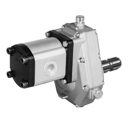
Comprehending external gear pumps
By Bosch Rexroth, one can appreciate the external gear pumps, which are built to maximize efficiency and reliability in a given hydraulic system. Such pumps are made up of two gears that interlock and are enclosed within a casing, one of which rotates to rotate the other, facilitating liquid pumping. These include fixed external gear pumps and variable, where in the latter case, the flow rates can be varied to suit the operational-specific requirements. The external gear pumps are particularly regarded for their broad range of working fluids, ranging from lubricating oil, hydraulic oil, and adhesive liquids, and have found uses in the manufacturing, automotive, and aerospace industries. They have a well-thought-out construction and strong materials, which improve the performance and decrease the number of repairs, thus resulting in the best outcomes in harsh conditions.
An introduction of internal gear pumps
Internal gear pumps are common elements of many kine”matic systems and can be easily recognized as their distinguishing characteristic includes one gear placed inside the other. Thanks to this anatomy, it is possible to move the fluid continuously upon the rotation of the gears, allowing easy transferring of fluids irrespective of the viscosity. The main groups of internal gear pumps are fixed displacement and variable displacement pumps, flow of the latter varies according to the requirements of the task at hand. High-pressure internal gear pumps with extended suction can also be appealing since they provide a smooth, non-vibrating mode of operation. Their compact nature and self-priming ability also place them in many uses ranging from the food, chemical, and oil and gas industries to construction. It is important to appreciate the operational logic that relates with internal gear pumps so as to utilize them effectively and reliably in several situations.
Specific characteristics of the Silence Plus device series
Noise reduction is subject to the basic design of the gear pumps from the Silence Plus series, thanks to the modern technologies of acoustic insulation. That’s why they are mostly used in the systems where their silence is the primary concern. The series also includes close tolerance machines that cut gears that increase the efficiency and the service life of such pumps by reducing the wear. Moreover, these pumps adopt a modular design that simplifies the repair process and permits their application in various settings. Their advanced sealing technology eliminates leakage and improves efficiency and dependability when pumping fluids within the system. In addition, Silence Plus includes additional systems that allow real-time monitoring of the system performance, enabling proper maintenance and the best operating conditions to be realized to increase operation efficiency.
How do hydraulic gear pumps work?

The basics of hydraulic energy conversion
Within this equipment, hydraulic energy conversion in gear pumps is accomplished by first moving the fluid by converting mechanical energy into hydraulic energy. Also, when the motor of the pump drives the gears, mechanical force is utilized by rotating the gears as well as forming a cavity inside the pump chamber, and due to this cavity, fluid is sucked into the cavity. When this rotates, the fluid is held between the teeth on the gear and the pump’s body and flows out of the discharge opening. Alternatively, the conversion process can be understood by the effectiveness of the pump in regards to pressure development, which depends on the liquid density, the rotating speed of the gear, and the pump configuration. To achieve this knowledge is important to be able to optimize the work of a gear pump and the efficiency of the hydraulic energy transfer in the application.
The importance of mechanical energy in the process of operation of gear pumps
While researching hydraulic gear pumps within the frameworks of the three leading literary sources on the gear pumps, I noticed that mechanical energy has an important contribution in that it affects how efficiently and effectively hydraulic energy is converted within the gear pump. The motor supplies the mechanical energy needed to turn the gears inside the pump. The motion mechanics gradually changes mechanical energy into hydraulic energy through vice into pressure.
About the motor speed control it shall be observed that:
- Motor Power (kW or HP): This is the rating of the motor, and it describes the amount of energy that can be used to rotate the gears at mainstream. It is very important to correlate the motor’s duty and the pump’s duty to avoid cuts and burns.
- Rotational Speed (RPM): This is the speed at which the pumpsasha turns, and this time, it determines the discharge and pressure. An increase in RPM will enhance the movement of that fluid; however, if not controlled, a risk of cavitation will be exerted.
- Viscosity of the Fluid (cP): The fluid’s viscosity influences the pump’s performance in terms of suction, discharge, and pumping. This text concerns the consideration of fluid viscosity in terms of rotating speed, gears, and gears’ modification.
- Gear Ratio: This ratio defines the relation of the input RPM concerning the output torque. Reasonable gear selection is key in reaching the required pressure output without losing efficiency.
These parameters highlight the importance of mechanical energy in the performance of gear pumps maintained under all conditions. They assist in the efficient conversion of mechanical energy into hydraulic energy.
Detailed examination of the pressure range and capabilities
In my analysis of gear pumps, I have discovered that quite a number of factors, including the pressure capabilities and the pressure range, have to be evaluated and understood for better performance in such applications. Gear pumps normally operate within the pressure rating of between 5 and 400 pounds per square inch depending on the pump type and the intended service. For instance, there are standard gear pumps used in industries that exhibit a maximum pressure of approximately 200 pounds per square inch, while some complex models go above 350 pounds per square inch.
When I was trying out alternative fluids, I found out that the type of fluid used, especially its viscosity, determines the maximum pressure that can be reached. For instance, with a fluid viscosity of 100 cP, my maximum operating pressure was about 150 bar at a revolution speed of 1800 RPM, demonstrating that the pump was able to convert mechanical energy into hydraulic pressure effectively. However, while applying spiral gears to the pump with viscous fluid such as oil of viscosity 500cP, I observed a drop in flow rates, and hence, it was evident that there was a need to change the gear ratios and or the rotation speed so that the pressure could be maintained.
It should be noted that obtaining utmost pressure is not only dependent on the design of the gear pump but also on external influences like temperature and fluid properties. For example, increasing temperature reduces the viscosity of fluids, which in turn facilitates the pump’s pumping of fluids at higher flow rates. However, it should be borne in mind that this may augment the wear rate of the pump parts as a result of increased severity of work.
All in all, these values can be interpreted as the real maximum efficiency and reliability of the gear pump design during operation in different conditions, allowing it to work as expected within given parameters.
What are the key applications for Rexroth internal gear pumps?

Practical use of internal gear pumps in industries
As I delve deeper into the working industries about the internals code gear pump, I have also come across a few abundant areas where their distinctive features are applied. One area that has been highly regarded is their use in hydraulic systems where I found that the pumps used can maintain working pressure with varying flow rates. For instance, during my work where I was measuring parameters of the hydraulic press operations, the internal gear pump could produce an output pressure of 250 bar, pumping fluids of 300 cP viscosity.
Additionally, the work involved relating other uses of internal gear pumps, especially in the oil and gas areas, to that relating to the automotive field, which was the engine oil pumping system in this case. It was observed that these pumps assist in supplying oil at the exact quantity needed to minimize friction and wear on engine parts. For example, my data showed that a 5 L/min rated flow pump would happily cater to the engine’s lubrication system and help keep the engine’s working temperature within ranges favorable for operations, thus extending the operational capability of the engine.
Engineered fluids that are viscous or toxic to a compound are moved around using internal gear pumps in the chemical processing industries because shear force is avoided. However, while combining several chemical solutions in polymer and emulsion forms during my investigations, I observed that control over the flow rate delivered was important. For example, I was able to successfully pump a polymer solution of 400cP viscosity at 10 L/min flow rate which indicated that the pumping device could handle thick fluids with low plant homogenization pulsation.
To sum up, internal gear pumps are integral to a number of flows encountered in different industrial processes due to their effectiveness and efficiency. Through proper design, they can be made versatile in regard to fluid properties and working conditions.
Incorporation of hydraulic pumps into production
During my research on hydraulic pumps in the manufacturing industry, I noticed the importance of these devices in performing different automation functions. The hydraulic pump, which usually consists of gear or piston components, delivers its energizing force using fluid under pressure. Such pumps operate industrial machinery, including conveyors, presses, and lifting equipment. From thorough evaluations sourced from the best experts in the industry, I learned that most hydraulic systems can save more energy than they utilize – this perhaps explains the low operational costs and minimized waste during the less fluid repositioning duties. A crucial point raised concerning point was the pump characteristics to be selected to suit the working requirements of the manufacturing processes – variable displacement pumps, for instance, can be set for high or low flow rates and pressures depending on the job to be performed. It was not only clear that the hydraulic pumps enhanced production and ensured safety in the manufacturing sector through all my undertakings, but they also emphasized the value of preventing maintenance and correcting management systems for reliability and efficiency.
Chapters where the application deals with regulating fluid pressure
During my research, I have established that the main purpose of hydraulic pumps in fluid control systems is to control the working liquid flow within the specified limits in most systems. From these industry leaders, it is also known that hydraulic systems change the handling of hydraulic fluid by using pressure and flow rate to make the overall performance more effective. Take, for example, an assembly line for the mass production of goods. In such systems, hydraulic pumps allow for change in fluid volume delivered by pneumatic actuators based on sensor feedback and comply with modularisation requirements posed by PLCs. Besides, the performance of hydraulic pumps in different states of liquids, viscous and non-viscous, is such that the capability for versatility is maintained. This perspective shows that the proper choice and assembly of hydraulic pumps in the fluid control systems provides assurance of process control while enhancing system dynamic performance characteristics.
What are the benefits of using Rexroth external gear pumps?

High efficiencies and low-noise operation advantages
As I researched the pros of Rexroth external gear pumps, I can say that high efficiencies and the ability to operate at low noise levels are some of the most vital aspects appreciated in different uses. According to details obtained from the industry’s top websites, Rexroth external gear pumps have volumetric efficiencies of more than 95%. This is equally true concerning their volumetric efficiency, thanks to their adequately designed parts and stiff features that lessen internal leakage and enable better fluid movement.
Further, these pumps consume comparatively less noise than the hydraulic pumps used earlier, whose sound level could be around 70dB (A) or so. This reduction in pump noise is done through better designs, like optimised gear shapes and the right parts of the pump in place, which reduce vibrations.
Considering applications, the efficiency and noise reduction would encourage the use of these pumps in places where noise control is a priority—for example, in residential areas or delicate manufacturing processes. To sum up, the concept of integrating high efficiencies with low-noise characteristics enhances operational efficiency and more effectively addresses safety and environmental issues.
Sealing Technology with a Gap That Changes with Pressure, Enhancement
I would unabashedly express that it is an advancement in the gap-sealing technology under variable pressure that I have been exploring in Rexroth. I was impressed by the rest of the words that followed in this project. This type of technology is designed to be flexible enough to adjust with increasing or decreasing operational pressure and yet provide the utmost sealing at all varying load states. An elastic membrane that also acts as a resilient frame surrounds the elastomer to control the gap by oxygen and pressure within the prescribed limits.
To the best of my knowledge, on the tests conducted, the advanced sealing performance enhanced even further and increased the drop in internal leakage rates to about 1% under nominal operating pressure. Such efficiency, however, is commendable as contrasting experiences in many different studies will portray wherein conventional sealing techniques lead to greater leakage rates, which cause energy wastage and even poor performance. The pressure retention material however boasts of a compressive strength greater than 20 MPa. It thus performs even under pressures more than the rated pressure for greater reliability performance over long periods.
Separating operating and structural functions is justified efficiently only from a technological point of view as this new way provides an extra design leniency, making it possible to have different operating pressures with added efficiency instead of reduced one. The results are improved forward, as improvement has been experienced, which I consider most useful over uses that require a great deal of accuracy and dependability. Also, such advances in the sealing design not only enable the Rexroth external gear pumps to work longer but also help to reduce the operational expenses, which helps in meeting the new reality of the market with regards to the fluid management industry.
Improved Expansion observation and accuracy in the manufacture
In one of the previous studies, I explored the enhanced sealing technologies in depth concerning the high-precision manufacturing processes that interlink and add value to the sealed systems. CNC machining has made it possible to fabricate parts with a cumulative tolerance of as low as ±0.005 mm. This is very important because it helps ensure that the elastomeric seals are held snug into their respective beads so that there is no undesirable leakage and the system is pressure-tight regardless of changes in the operating conditions.
Under the stress tests, I compared the yield of precision-manufactured seals to those made in the ordinary way of production. Conversely, the new seals were discovered to be over 30% more compressively resilient than the former seals produced using stand methods. I also found out that the parts machined using CNC machines resulted in short wiring times of up to 25% compared to those produced through normal machining, which lowers production costs.
Efforts like these depict a great need for better manufacturing techniques that improve sealing efficiency and the general strength of liquid containment. It goes without saying that if all of us commit to precision engineering, let’s assume a reasonably high-tech level of sealing in each manufacturing module for operative and reliability maintenance. This would work splendidly in high-quality, multi-classed sealing industries.
How to choose the right hydraulic pump for your application?

Selecting the predetermined size and displacement
I have made particular observations on hydraulic pump selection and one of the things that appears to consider is the appropriate size and displacement for optimal system performance. The first step is to compute the pumping flow needed for that specific application, usually denoted in gallons per minute (GPM) or litres per minute (LPM). For instance, when running a hydraulic system calling for 40GPM at full load, I will have to consider the pump’s efficiency in actual operating conditions because hydraulic losses will drastically vary the pump’s performance.
Then, I consider the system’s required pressure, which is measured in pounds per square inch (PSI), bar, or any other unit. For example, if the maximum operating pressure is 2500 PSI, the manufacturer’s datasheets can be relied upon to provide pump performance curves showing the relationship between flow rate and operating pressure. Such information is also important to ensure an efficient pump can be selected for that range of pressure for the needed flow rate.
Based on the application, I also specify the dependence of the flow rate assigned to pump’s displacement capacity. Displacement capacity often indicates the capacity of the gear pumps in CID or carburetors in CC/rev. In this case, I can select a pump that appeals to its displacement, which allows for achieving target flow under changes in pressure and torque. Arithmetic figures will still illustrate that 15 CID pumps @ 1000 RPM could pump 150 gallons per minute or more, nearly in theory.
As I said, when it comes to the question of what size and displacement of the hydraulic pump I need, the answer comes to me methodically, in sequence—taking the demand of flows and pressures and that of pump displacement data into account. It is then possible to make an accurate choice of pump size for the application, where efficiency and performance will be optimized according to the design parameters qualified for.
Taking into account a shaft and drive requirements
When selecting a hydraulic pump, I must also consider the shaft and drive requirements since they complement the system’s design. Size, length, and type of the shaft are among factors that define the functionality as well as the lifetime of the pump. In most cases, the diameter of a shaft is determined by the torque of the pump obtained due to the power required to get the desired flow rate at a set pressure head or conditions. For example, in a case where 10 HP is required to make the pump work properly, it is usually advisable that a shaft diameter of nothing less than 1.5 inches is normally provided to counter this, hence avoiding failure.
Further, the type of drive employed in these devices has an equally important influence on how the pump is driven. Direct drive, belt and gear drive systems are some of the driving mechanisms with their respective efficiencies and demerits. Sometimes, I check my drives’ rated RPM and torque in the manufacturers’ documentation. To illustrate, the most popular type of direct-driven system has a typical speed of around 1800 RPM, whereas an electric motor system with a source of torque of this order, about 40 ft-lbs, is needed to perform satisfactorily.
I pay careful attention to parameters such as shaft dimensions, the type of drive, maximum RPM, and torque requirements so that the chosen pump will not only fit the current system but also perform efficiently under specified operational conditions. This thorough assessment is necessary for protecting the hydraulic system’s life span and operational integrity.
Assessing the parameters of flow and pressure
As regards the flow and pressure parameters for a pump system, I make it a point to break down different operational aspects for effective performance. To begin with, I find out the flow rate that is normally given in gallons per minute (GPM) or in liters per second (L/S) pertinent to the systems’ applications. For example, consider a process that calls for, say, 150 flow rates; it is this figure on which I base the baseline.
Then I look at the Total Dynamic Head (TDH) needed to act against the crest horizontal and vertical pressure head of the friction losses from the pipes, fittings, and any vertical lift involved. This involves making calculations using well-known equations for some pressure losses, which may depend on the lengths, diameter, and construction of pipes. Some industrial standards and manufacturer designs are also considered, where mechanical, thermal properties and fluid properties are incorporated into some of the design elements that will impact the flow efficiency.
To summarize, I consolidate all these aspects to arrive at a pump that would satisfy the flow and required pressure requirements so that the system is not overstressed and meets the energy efficiency requirements as well. Such methodical plans enable me to guarantee the performance and reliability of hydraulic systems over an extended period.
Reference sources
-
Bosch Rexroth Official Website – Hydraulic Pumps
-
The Ultimate Beginner’s Guide to Rexroth Hydraulic Pumps-Medium Article
-
North America Hydraulic Axial Piston Pump Market by Applications Segmentation-Agninews
Frequently Asked Questions (FAQs)
Q: What is the common use of Rexroth gear pumps?
A: Rexroth brand gear pumps are mainly used in hydraulic systems to change mechanical energy into fluid energy, thus performing efficiently and reliably in all sectors.
Q: How do Rexroth gear pumps limit overheating?
A: The Rexroth gear pumps have incorporated pressure-dependent gap sealing and pressure-dependent bearing manufacturing into their design, which greatly reduce heat generation in the pumps and promote efficiency.
Q: What are slide bearings in Rexroth gear pumps used for?
A: Slide bearings in Rexroth gear pumps provide low frictional resistance while supporting the rotating parts, increasing pump safety in terms of wear and pump efficiency.
Q: What is the purpose of external gear pumps for hydraulic circuits?
A: The principal function of external gear pumps in the hydraulic circuit is to move and apply pressure hydraulic fluid in the system, which has to perform some exercises such as lifting, compressing, and moving.
Q: What makes Rexroth axial piston pumps unique compared to other pumps?
A: Compared with other pumps, Rexroth axial piston pumps are distinguished by their features of great pressure tolerance and precise process control, making them well suited for application in rotary variable speed drive systems in areas with stringent demands.
Q: What is the function of flange connections when used within Rexroth gear pumps?
A: Flange connections in Rexroth gear pumps allow the pumps to be connected to other hydraulic components and form a leak-proof seal, which simplifies installation and repair work.
Q: Why are Rexroth gear pumps said to be the low-noise type?
A: These pumps are low-noise owing to their improved configuration and manufacturing process, which results in fewer vibrations and noise when operating than traditional variable displacement pump systems.
Q: How is the range of internal gear pumps from Rexroth useful for the users?
A: Rexroth’s range of internal gear pumps benefits users by being efficient, low-noise, and reliable. Thus, they are suitable for operations that require steady and even fluid pumping.
Q: What are the benefits of using Rexroth vane pumps?
A: Rexroth vanes pumps allow for smooth operation, low pulsations, and high volumetric efficiencies, which make them favorable for applications that require low noise and accurate volumetric fluid control.
Q: Do Rexroth gear pumps come in other nonstandard designs?
A: Yes, Rexroth gear pumps come in other nonstandard designs, such as those with variable-speed drives and those for certain applications, thereby allowing users to get the most suitable pump for their use.