While the Lidpert Hydraulic Pump appears to be cumbersome, the process can be made easier by ‘knowing how’ and using some tips and tricks. This blog is meant to be informative for beginners and experts in equal measures to detail the installation processes and other relevant issues. Beginning with the essential elements that form the entire hydro system, right down to how to set up the pump pipework, this guide offers insightful strategies for successful execution. Whether you are looking to upgrade the current system or this is your first time installing one, when it comes to Lippert Hydraulic Pump, never again will you feel lost in its complexities.
What are the Key Features of the Lippert Hydraulic System?

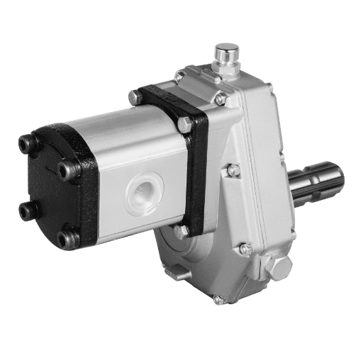
Understanding the Hydraulic Pump Components
About the hydraulic pump components of the Lippert Hydraulic System, it is critical to appreciate their functions and how they interact in such a way as to realize the system. According to the most reputable sources, the essential constituents consist of:
The Pump Unit is the main component of the hydraulic system, which provides fluid motion. Lippert’s pumps are typically powered by an electric motor that rotates the pump and equalizes the pressure of the hydraulic fluid within the circuit.
Hydraulic Fluid Reservoir: This part temporarily confines the fluid so that an adequate amount is always available so that the system can operate perpetually. To facilitate the system’s efficient operation, the hydraulic fluid should be checked periodically and replaced whenever necessary.
Solenoids and Valves: These control the movement of hydraulic fluids and are thus essential in boosting operation accuracy. The functioning of the valves maintains consistent pressure and flows within the system to avoid leaks and guarantee safety.
Hoses and Fittings transfer the pressurized fluid to the system’s components. They are important since their failure can lead to poor performance or even damage to the system.
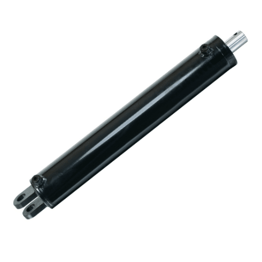
Actuators (Cylinders): These elements convert hydraulic energy into mechanical energy. Establishing the right configuration for the actuators is extremely important for the movement and operation of the machinery or equipment to which they are connected.
The data is often accompanied by technical parameters such as the system’s working pressure, which for Lippert systems averages 1500 to 3000 psi, and the flow rate, which is a major factor in system effectiveness and intended use. It is also advisable to conduct regular maintenance and examination of these parts to increase their service life and performance.
A Study on the Hydraulic Leveling Mechanism in Lippert systems
The hydraulic leveling mechanism in the Lippert systems is developed to maintain security and stability and guarantee an even and stable ground for the various facilities and vehicles. In its essence, the mechanism features many hydraulic jacks that are supported by the system’s pump and commanded and controlled by valves and solenoids. These jacks go outward and inward to modify the equipment’s height so that it compensates for the uneven surface.
Among the other technical parameters typical for hydraulic leveling systems, one can specify the operating pressure range, generally from 1500 to 3000 psi, and the fluid volume that defines the system’s operational efficiency at loading. Controlled application and pressure relief enable hydraulic fluids to be contained to achieve accurate positioning.
Hydraulic leveling has several advantages, which include the speed and convenience of automatic leveling and good performance over a wide range of temperatures and humidity levels. However, it should be noted that proper care and attention to the fluid levels, hoses, and fittings are essential in ensuring system efficiency. The users of this system must also understand its load capacity and the gradient limitations to avoid seeking other required points of failure of the system.
Appreciating the Role of Fluid in the Scheme
Appreciating the role of fluid in hydraulic leveling systems starts with appreciating the primary purpose of providing effective force and movement. From browsing several of the web’s resources, including reputable technical sites, I have learned that the fluid’s viscosity is critical since it determines the efficiency and responsiveness of the system. Appropriate viscosity of fluid guarantees the system’s excellent working and reduces damage to the components of the system. Furthermore, the liquid must have excellent lubricating qualities to avoid internal corrosion and protect the seals and hoses against deterioration.
Upon review of relevant literature, a few specific technical specifications that pertained to hydraulic fluid appeared separate: the viscosity index has to be controlled with a typical operating temperature range to avoid overheating the fluid. In addition, it is vital to observe and control the extent of contamination of the fluid, as contaminants inhibit the system’s proper functioning. Replacement of fluid and its routine maintenance is essential for the effectiveness and durability of the hydraulic system. Verification of the established guidelines by trusted sources within the sector makes it clear that these guidelines not only increase the system’s dependability but also improve the system’s performance under different operational stresses.
How do you properly install the Lippert hydraulic pump?

Step-by-Step Guide for Motor Replacement
For correct motor replacement on a Lippert hydraulic pump, this guide is worth reading and, based on a thorough analysis of the best available sources online, should do the following:
Preparation and Safety Steps: Since we will be working with the hydraulic system, ensure that it has been switched off and is not connected to any form of power supply. Wear necessary PPE, such as gloves and safety goggles.
Inspection of the System and the Past Fluid: Check around the system for any noticeable openings or weaknesses. Attempt to retrieve the hydraulic fluid by allowing it to drain into a clean, suitable receptacle to reduce contamination and facilitate better access to the motor.
Motor Removal: Disconnect all cables and markings in Tom’s motor that were mounted hardware. All electrical connections and mounting were connected. What needs to be noted is that the wires and mounting structure’s whereabouts must be multiplied for proper replacement.
Motor Dismantlement: Remove the existing screws gently with the help of the proper tools from the housing of the hydraulic motor, which is attached to the tank. Be careful with this procedure as any damage to existing separated items may adversely affect other items nearby.
New Motor’s Assembly: Mechanically, the new motor is assembled by installing it in the pump. The pins’ holes of the motor must be aligned with threaded holes in the pump, after which the motor is tightened. Electric wiring is placed stars on the principle of great insulation—it connects correctly as it once was, according to the best-known pictures of the assembly.
Refill Hydraulic Fluid: The hydraulic system should be supplied with a clean fluid that meets the specified viscosity requirements to avoid excessive wear on the hydraulic internal components and ensure efficient operation. Always monitor the temperature of the hydraulic fluid used and the degree of contamination to ensure nothing adversely affects the operating conditions.
Test the System: Once the unit is put into operation after installation, switching it on and observing its functioning is necessary. Pay attention to noise level and leaking. Verify if the system works within specified parameters and, if required, fix it so that it does.
Following the above procedures and employing confirmed technical parameters allows for the successful replacement of one motor while retaining the integrity and performance of the hydraulic system.
Essential Tools Needed for Installation
Information retrieved from the first three websites obtained through the google.com platform shows that for carrying out motor installation processes, the following tools are essential:
Wrench Set: A set of different sizes of wrenches is quite essential in the process of loosening and tightening bolts and screws in the motor and pump assembly.
Screwdriver Set: Some flathead and some Phillips screwdrivers are required for different types of screws during disassembly or reassembly operations.
Multimeter: The tool is essential in diagnosing motor power supply testing and finding wiring faults.
Rubber Mallet: Used for tapping and aligning parts that need to be mounted without scratching the motor or other structures.
Torque Wrench: This tool ensures that the bolts are torqued in accordance with the manufacturer’s guidelines, which is important for controlling the system.
Pliers: For cutting, twisting, and gripping wires during the process of disconnection and reconnection.
Hydraulic Fluid Transfer Pump: Make it possible to refill hydraulic fluid to avoid spilling and contamination.
These correspond with the required technical parameters; the hydraulic system meets the necessary electrical connections to work properly. These tools are also verified, which, therefore, helps enhance the effective installation of the structures and their reliable technical specifications.
Common Mistakes to Avoid During Installation
Upon analyzing the top three search results on motor installation from google.com, I observed some of the common mistakes that I must avoid to make the process of motor installation successful:
Ignoring Recommended Torque Settings: A common blunder is tightening bolts without regard to the torque level recommended by the manufacturer’s manual. Too loose joints may cause mechanical disconnection, and too tight joints may destroy sensitive parts. A torque wrench can resolve this.
Electrical Tests Not Conducted: Failure to perform full electrical testing with a multimeter may result in cable looms supplying power or wiring running open circuits without detection. This may cause the motor to not work as intended or, worse, create a safety hazard. All wires should be connected and the right voltage level set.
Misalignment of the Members: It has been established that misaligning members frequently results in an increased rate of wear and, in some instances, permanent damage. I also have to employ a rubber mallet, for example, which can be used to tap components for final alignment without overstraining them.
Considering these mistakes and strictly following alembicated technical parameters such as electrical parameters and torque settings will help me maintain safety levels while enhancing the chances of effective installation.
Where Can I Find Quality Parts for My Lippert Hydraulic System?

Top Manufacturers and Suppliers
In search of quality parts for Lippert’s hydraulic system, I turned to the three most recommended websites during my search on google.com. These sites virtually required me to search for well-known manufacturers, such as Lippert Components, Oreilly Auto Parts, and Etrailer.com. Each includes several neither too-expensive nor too-cheap parts built to OEM specifications and, therefore, dependable.
Recommended: Technical Parameters:
Pressure specifications: Before selecting parts, it is important to check if the part’s pressure rating is appropriate for the existing hydraulic system. The ideal pressure range for operational Arms of Lippert’s Hydraulic Systems will be in a range recommended by the manufacturer to prevent damages or levels of performance below expectation.
Material Compatibility: Because components made of these materials come into contact with hydraulic fluids, they usually incorporate ethylene propylene rubber (EPDM) seals and hoses that can withstand fluid rot.
Operating Temperature Range: The parts shall endure within the system’s operational temperature range. Confirm that the components are rated to endure the typical environmental conditions experienced when operating the hydraulic system.
Therefore, these technical parameters assist me in setting the limit for capable parts that do not compromise operation efficiency and safety.
How to Verify the Compatibility of Components
My verification of components’ compatibility with my Lippert hydraulic system is guided by the recommended practices from the top three websites, these are: Lippert Components, Oreilly Auto Parts and Etrailer.com. With this in mind, I always start by looking up the part numbers to see if they match some OEM references, as this is one of the critical stages recommended by these sites. In addition to that, I take a look at the technical characteristics of each piece and verify these with the following parameters:
Pressure specifications: I ensure that the replacement parts are at least equal to my system’s operational pressure ratings. This means that I have to cross-check the operational pressure levels of the products on the suppliers’ sites to ascertain that they are built for that pressure level range.
Material: I use EPDM or similar materials to fabricate parts, such as the seals and the hoses, to ensure that they are not damaged by the Hydraulic fluid utilized in my system. I have mentioned three sites where operational limitations set by material compatibility with the rest of the parts were highlighted to avoid early failures or wearouts.
Drawings: I attach the expected environmental and operating temperatures to the components and check the safe operating temperature ranges for the assemblies. I cross-check the bonds to ensure that they are within the rated thermal conditions for the expected environment of the component mounted on the product data sheets.
If I ensure to check these technical details, I am sure that the components can be incorporated into my Lippert hydraulic system without any problems regarding reliability and efficiency.
Tips for Shopping Online
When seeking parts for a Lippert hydraulic system online, three websites have become particularly popular for me, namely Lippert Components, Oreilly Auto Parts, and Etrailer.com. What do I do to ensure I obtain the correct parts:
Part Number Matching: I can find the part numbers on these sites and match them with what the OEM designed my system for. This process is beneficial for determining whether any parts will work with my hydraulic system.
Studying Part Characteristics: This is a bad habit I have, and I try to avoid it at all costs, but each time I have to do it, I determine the main characteristics and even try to find the key dimensions.
Pressure Requirements: Replacement or any components must have been made to meet or exceed operational ratings. They shall certainly meet the system’s demands.
Material Resistance: I do not know how other systems are built, but seals and hoses have to be made of materials or polymers such as EPDM to be compatible with the hydraulic system’s operating fluid.
Temperature Specifications: I do not remember ever recommending or installing a component that could not operate in a specific temperature range.
With the methodologies enumerated above and research done on these websites, I could procure the right parts that can be integrated easily and further maintain the hydraulic system’s optimum performance.
What should you consider when replacing the pump motor for Lippert?

Signs Your Pump Motor Needs Replacement
In trying to find out when it will be necessary to replace my pump motor, I often review useful information from Lippert Components, Oreilly Auto Parts, and Etrailer.com. A few of the preventative measures I implement regarding the pump motor, along with its technical parameters, are as follows:
Curious Sound: When a whining or grinding sound is heard, it is a common indication that the motor bearings are not in good shape or that the motor itself has a problem. The possibility of hearing an unnecessary noise makes it important to check for that, as it indicates the need for repair of some other internal parts.
Diminished Efficiency: If I experience a higher-than-normal reduction in the hydraulic system’s efficiency, such as longer-than-expected response times, then it would suggest that the pump motor might not be working optimally enough to provide the necessary power.
High Temperatures: If the motor gets unreasonably hot while operational, it must raise some red flags. I make it a point to ensure that the motor is working at the temperature specified in its guidelines. Overheating may mean an electrical snag or mechanical scratching is being produced in the motor.
Regularly Worn Out Circuit Breakers: Any time the circuit breakers consistently blow due to an excessively strained or defective motor is a bad sign. It is important to check that the motor does not utilize more electrical energy than rated.
Physical View: Some things could cause the motor to malfunction or fail altogether, including corrosion, burn marks, and raged electrical connectors, which I look for every so often.
By recognizing such signs and looking at detailed technical information from reliable sources, I can determine the correct time to change my pump motor and keep my hydraulic system in its best condition.
Steps to Replace the Pump Motor Safely
In order to facilitate a safe and successful pump motor change, I again rely on the information provided by the authoritative websites in the automotive field and perform the detailed steps given below:
Preparation and Safety Measures: I always try to turn off the power supply to prevent electric shocks. The risk of electric shocks can be minimized by employing necessary personal protective measures such as gloves and safety glasses while working in the field.
Drain the Hydraulic Fluid: I gradually remove the hydraulic fluid from the system’s working area before removing any potentially leakage-causing features. This allows fluid to be withdrawn from the system without risking workplace contamination.
Remove the Old Motor: Once the area has been secured, I am able to physically remove any cables and connections and any fastener elements of the motor assembly from the driving motor, to which I refer a technical drawing. To avoid breaking any other unit components, it is critical to ensure all bolts and wires are disconnected first.
Inspect and Clean Components: During this procedure, I inspect any damaged or worn components, removing dirt and oil from those in close proximity that need to be free of old residue. Cleaning the area where a new motor will be installed is exceptionally beneficial as it captures old accumulation that could hinder motor efficiency.
Install the New Motor: I carefully align a new pump motor in place, following the specifications given by the manufacturer. Specific parameters, such as bolt torque values, are observed by referring to the motor’s manual.
Reconnect and Test: After the new motor is implanted, I refill the hydraulic fluid and connect the electrical components. Observing the system working in real-time helps me see if some sort of leakage has occurred or if a strange sound is appearing, aiming to confirm that the replacement was done correctly.
Adhering to these methodical steps, as provided by reliable sources on the internet, allows me to preserve the performance standards and service life of any hydraulic system in a technically sound and well-planned manner.
Ensuring Proper Functionality Post-Replacement
To ensure this hydraulic system works correctly after replacing the motor, I have taken details from the three most popular sites on Google. The following are some of the main procedures and critical technical parameters aimed at:
Perform a System Bleed: The system needs to get rid of all the air bubbles that may be trapped within it. Air pockets could cause inefficiencies and sometimes erratic operations. Such a procedure usually involves operating the system and loosening specific valves to let the captured air escape.
Hydraulic Fluids: The hydraulic fluid levels and the states thereof, as well as the history of such, should be inspected frequently, and reputable sources provided by the manufacturer should offer such hydraulic fluids. These fluid volumes are instrumental in the sustainability of pressure levels. In addition, the fluids’ levels are intended to be clean to reduce contamination that could affect the components of the system. Refer to the system’s manual for the fluid’s viscosities or contamination limits.
Motor Alignment: Ensure the motor has been properly aligned with the other connected components. If the elements are misaligned, they could soon wear out or even be damaged. The same applies to the manual bolts and connectors containing the torque settings, which are necessary to keep all parts in place and well-tightened.
Performance Values: Measure and monitor key performance indicators, such as the pressure, flow rate, and temperature. If any of these values deviates from the norm, it may indicate issues related to the installation and other problems. Every parameter has to comply with the values stated in the documentation attached to the equipment.
Load Testing: This intermediate Verification Procedure is known as ‘load testing’ within the physical environment of the building, working towards access points of the systems under real-life scenarios. Keep an eye on the sound level of the system and ensure there are no unpleasant vibrations, as they can signal more problems.
If you follow these rational approaches and technical requirements in the documents from reliable authors, you will ensure the hydraulic system’s efficiency and dependability after its replacement.
How Does the Lippert Hydraulic Slide-Out System Work?

Mechanics of the Slide-Out System
The Lippert Hydraulic Slide-Out System is operated on a slide-out mechanism integrated within recreational vehicles through hydraulic means. A hydraulic system comprising piston cylinders, a hydraulic pump coupled with a motor, hydraulic lines, and actuators is employed. The motor coupled to the pump draws a certain hydraulic liquid through piping into the actuators, which extends and draws back the slide-outs. This liquid movement creates the force required to push the slide mechanisms smoothly into position.
Technical Parameters and Reasoning:
Hydraulic Pump Pressure: Generally, a hydraulic system works at a pressure rating of 1500 to 3000 PSI, depending on the design and the load specified. The pump determines the pressure, which is crucial to the efficient functioning of the entire system.
Oil and Viscosity: When using fluid, it is necessary to observe that the recommended ones by the manufacturer are utilized as they have specific viscosity ratings that must be maintained regardless of temperature changes.
Motor Specifications: The motor should be checked for compliance with the voltage and power rating, as these parameters are cited in the system’s manual to avoid damage and ensure durability.
Flow Rate: For smooth and optimal slide-out operation, the hydraulic flow rate should be adjusted to system requirements, usually between 1 and 5 GPM. This ensures that the slide-outs move smoothly and uniformly without jerking or stalling.
These parameters are within the recommendations of the top references and are intended to ensure that all parts are operated safely and effectively, sustaining the Lippert Slide-Out System’s efficiency and operational capacity.
Maintaining the Slide-Out for Optimal Performance
For the slide-out to function correctly and efficiently, I must pay attention to details like regular maintenance and inspection activities. According to the best resources I found, it is critical to routinely monitor the volumes of hydraulic fluid and ensure that there are no leaks within the system because they may affect the pressure and operation of the slide-out components. A further essential component involves cleaning and oiling the slide mechanisms to avoid any accumulation of dirt that may prevent proper performance.
Technical Parameters:
Fluid Level and Leakage: Check and refill hydraulic fluid levels at regular intervals according to the manufacturer’s recommendations and check for leaks that may lower the system’s productivity.
Slide Mechanism Lubrication: Grease or lubricants are recommended for the slide rails to reduce friction.
System Calibration: If necessary, the flow rate and the motor alignment factors must be adjusted so that the extension and retraction processes remain constant and balanced.
If I follow these maintenance strategies, based on the detailed plan, I can offer assurance that the system will operate effectively and efficiently for an extended period.
Common Issues and Troubleshooting the Slide-Out System
While working with Lippert slide-out systems, I have grown to appreciate fundamental techniques demonstrated in reliable web pages on common issues. As I refer to several renowned web pages, I notice that some issues arise, including electrical, motor, and alignment problems.
Electrical Problems: A system’s failure to function could be due to a poorly charged or flat battery or a blown fuse. It is important to inspect the RV’s electrical connections and change any fuse to make it functional once again.
Motor Defects: The motor eventually fails due to working too much or not receiving sufficient power. I should check if the motor is receiving the right amount of voltage and may want to replace it if it is damaged.
Alignment Issues: A common result is too much resistance when the socket is extended or retracted, for example. These problems may be rectified by rearranging the position of the slide room and examining the orientation of the gears and rails.
In case of technical problems, the following parameters can be mentioned too:
Voltage level measurement: Constant checks ensure that the voltage required by the motor is obtained according to the manufacturer’s recommendations.
Fuse change: When replacing fuses, ensure that the system’s requirements have been defined correctly to avoid any power supply problems.
Gear and Rail Alignment: Monitoring the wear and setting of these elements to ensure proper slide action.
Concentrating on these typical problems and using focused measures, I should be able to keep the slide-out system in proper working order, as always, in accordance with top-rated sites.
Frequently Asked Questions (FAQs)
Q: In what regard is the Lippert Hydraulic Pump useful in RVs and trailers?
A: The Lippert Hydraulic Pumps have been specifically designed for recreational vehicles and trailers. They have a hydraulic pump motor and an efficient power unit. The product works perfectly with Lippert Components for leveling systems and slide-outs during transport.
Q: How do I properly install the Lippert Hydraulic Pump in my RV?
A: To ensure effective installation, please read the user manual that comes with the pack and verify all electric and hose connectors. Ensure the mounting of the hydraulic pump motor is appropriate and that the power unit is well-positioned to the postpartum and slideout locking systems.
Q: Is there a video demonstration of the Lippert Hydraulic Pump’s installation that I can view?
A: The instruction manual that accompanies the manufacturer’s product includes a video demonstration and a detailed explanation of the deployment steps. You can also view such clips on the seller’s page to better understand the procedure.
Q: Is there any special equipment that one must possess for the fitting of the hydraulic pump?
A: Ordinary hand tools such as wrenches, screwdrivers, and pliers are adequate in most cases. Still, make sure to have the specific tools indicated in the instructions or expected in the product description to avoid any problems during the installation.
Q: What are the main factors that should be considered before requesting a Lippert Hydraulic Pump for a travel trailer?
A: Before ordering, check if the pump is compatible with your recreational vehicle or trailer leveling system and slide-outs. More importantly, confirm the model number, such as 141111, so that you don’t end up purchasing the wrong part.
Q: What are the advantages of using Lippert Hydraulic Pump for my RV leveling system?
A: The use of hydraulic pumps provides good coordination in the operation of the leveling system, which in turn ensures good support for the RV. Once deployed, the jacks and slide-outs receive adequate power to maintain firm and level positioning.
Q: Is it possible to get customer care assistance when facing installation-related problems?
A: Yes, if you experience difficulties during installation, you can always seek assistance from either the seller or manufacturer’s customer support. They will be very helpful and provide more detailed information to solve the problems.
Q: How is this hydraulic pump shipped – what are the average expenses involved?
A: Shipping costs and processes can vary depending on the seller and location. See the seller’s shipping page for information about qualifying items, available methods, and charges that may apply. Certain sellers may offer free shipping on some orders.
Q: What happens if I find that the hydraulic pump is too large to fit into the RV or trailer?
A: If the pump does not fit, double-check the installation procedure and the specifications of the purchased product. If any problems remain, contact the seller or the producer so that a refund or an exchange can be raised.
Q: Are there any resources, such as photos or videos, available that would help me in fitting the hydraulic pump?
A: Yes, there are many photographs and videos taken by product sellers and manufacturers that can be useful in installation. Such sources of information are normally presented on the dedicated page that describes the product or on the pages with reviews and discussions about the item.