Various hydraulic systems greatly rely on hydraulic gear pumps, which are very important components that provide dependable and efficient fluid power for different purposes. Nonetheless, as with any mechanical system, these weaknesses can lead to inefficient work and total stoppage. This guide to fault finding will give the readers a technical basis for identifying and solving routine problems of hydraulic gear pumps. Understanding how it works and what may be wrong at any given time enables operators or technicians to use the appropriate remedial measures to get their hydraulic systems back in order. For each category, there will be an investigation about certain signs, check-ups, and treatments leading to the maintenance of these types of pumps.
Common Causes of Hydraulic Gear Pump Failure

There are many reasons why hydraulic gear pumps fail that can cause severe operational inefficiencies. One of the main factors is the pollution of hydraulic oil, causing abrasive wear on internal components and thereby reducing pumping efficiency, leading to its failure in the future. Too little lubrication due to inadequate fluid levels or inappropriate fluid properties may overheat the pump, affecting its internals further. Using a pump beyond its design specs also means that it has been overloaded, leading to mechanical failure due to excessive stress. When low pressure is introduced or when flow happens too fast, there will be cavitation symptoms where bubbles collapse violently, damaging the gears and housing of a pump. All these call for regular maintenance checks, fluid analysis, and adherence to operational guidelines to ensure reliability and longevity of hydraulic gear pumps.
Symptoms of a Failing Hydraulic Gear Pump
Numerous signs can show how a single faulty hydraulic gear pump behaves; one should look for specific symptoms attentively. Commonly observed symptoms include abnormal sound like grinding or whining sounds which might suggest either internal component wear or cavitation. An uneven discharge flow rate could be an early indication of potential pump failure arising from mechanical faults or contamination interfering with normal operation in this case. Additionally, hydraulic fluid overheating points out reduced lubrication or increased friction within the pump calling for immediate attention. Another sign might be greater operating pressure or pulsations in the whole hydraulic system since they affect system stability as well as efficiency at large; if recognized soon enough, these signals allow for saving the device.
Impact of Cavitation and Aeration on Gear Pumps
Hydraulic gear pumps have their efficiency and life spans greatly diminished by cavitation and aeration processes taking place within them. Cavitation occurs when low pressures inside the machine generate vapor clouds in the medium through which it operates. The vacuum created by collapsing vapor bubbles erodes metal surfaces and degrades internal parts, thus causing premature aging. Aeration is related to introducing air into hydraulic fluids making them less lubricative and more compressible. Mixed up, this results in an unstable flow which leads to erratic pressure and a decline in power generated by pumps. Aeration and cavitation both result in decreased system reliability, increased maintenance costs, and reduced operational efficiency. Potential methods of preventing these are therefore mandatory.To minimize the potential damage from cavitation and aeration, monitoring their impact on the performance of hydraulic gears regularly is important.
Importance of Hydraulic Fluid Viscosity for Gear Pumps
It should also be noted that the viscosity of hydraulic fluids plays a key role in determining how gear pumps will perform. Its thickness directly influences the flow characteristics within the pump and throughout the entire hydraulic system.Correct fluid stickiness ensures that all the pieces inside it are adequately oiled, leading to minimized friction or wear and increasing life span.Low viscosity may lead to incomplete film formation, hence increasing wear with probable component failure, while high viscosity creates resistance, especially at low temperatures, causing poor functioning as well as higher energy consumption levels.
Moreover, hydraulic fluid viscosity is temperature-dependent, so one should be careful in selecting the proper fluid to achieve optimal performance in a given operational temperature range. By fluctuating, temperature may alter fluid viscosity, thereby influencing the pump’s ability to generate required pressure and flow rate. As such, keeping the right hydraulic fluid viscosity values will improve its efficiency, minimize cavitation and aeration chances, and enhance overall dependability and endurance of hydraulic gear pumps. It will be necessary to make regular assessments and adjustments to maintain the right range of viscosities reflecting both environmental conditions and operating requirements.
How to Conduct Visual Tests on Hydraulic Gear Pumps

It is vital to carry out visual tests on hydraulic gear pumps in order to identify possible problems and ensure that they work efficiently. Specifically, start with a comprehensive examination of the external elements of the pump for any signs of leakage or corrosion. Pay close attention to the seals and connections as these sections are most susceptible to wear and may signal loss of hydraulic fluid.
To this end, the situation of the pump casing should be checked for cracks or deformations that might impede performance. Further than that, though, check that mounting hardware is present so that one can see if it vibrates during operation or seems shaky, and also ensure that intake and outlet ports aren’t blocked by anything.
Once you have completed the external inspection, remove access covers to assess the internal components visually. Inspect gear for pitting, wear or scoring and ensure consistent lubrication free from contaminants. Regularly conduct these visual tests so as to discover potential issues at an earlier stage thereby maintaining the dependability and efficiency of hydraulic gear pumps
Visual Inspection Checklist for Gear Pumps
- External Components Inspection
- Establish whether there is leakage around seals and connections.
- On pump body, connections, fittings inspect for corrosions.
- Pump Casing Assessment
- Look at casing for breaks or misshapen areas.
- Ensure no visible damage impacting hydraulic functionality.
- Mounting Hardware Evaluation
- Verify secure attachment between mount and pump.
- Watch out for signs suggesting instability like vibrations which could dislocate proper alignment.
- Intake and Outlet Ports Examination
- Scan through intake & outlet ports looking for blockages or debris therein.
- Ports should be clear enough to facilitate flow rate through them appropriately without any hindrances what so ever!
- Internal Components Inspection
- Gears with pitting, wear , or scoring when access panels are removed.
- Evaluate quality lubrication –ensure it remains consistent and devoid of contaminants.
- Fluid Level Check
- Make sure that hydraulic fluid levels meet the minimum requirement for operation.
- Presence of particles or change in color could indicate fluids that are contaminated.
- Operational Test
- It may be necessary to run the pump under operating conditions to test whether it runs correctly.
- Again, listen for any strange noises which could imply inner damages.
Identifying Leaks in Gear Pumps
The identification of leaks occurring in gear pumps is a very important thing. The first step is to observe the outside surfaces of the pump while focusing on areas surrounding seals and connections where fluid might accumulate as sign of leakage. If need be, use dye tracer or leak detection fluid to enhance visibility under UV light. Meanwhile, check if all fittings and bolts are tightened according to manufacturer’s specifications for effective mounting hardware. In addition, analyze hydraulic fluid quality as contaminants and emulsification can suggest internal leaks. When suspected leaks continue, pressure testing should be carried out on a system so as to locate its weak points precisely. This will ensure that gear pumps last longer by promoting their reliability during operations.
Recognition of Wear in Components of Gear Pumps
The assessment of wear in gear pump components is important for the effectiveness and extension of their working life. Start by looking at the gears to check if there are signs for scratches or uneven wearing off, which can show wrong alignment and bad lubrication. Inspect the housing for any cracks or erosion because these can jeopardize the integrity of the whole system. Monitor and evaluate conditions for bearings as well as seals; spoilt seals may cause leakage, whereas worn-out bearings may increase frictional resistance generation heat. Another good option is doing regular vibration analysis since erratic vibration normally indicates problems that are developing within a pump. Regular maintenance and thorough component checks enable timely detection of wear hence repairs/replacements can be done in time.
Effective Troubleshooting Tips for Hydraulic Gear Pumps
For effective troubleshooting of hydraulic gear pumps, it is important to approach the problem systematically to identify and resolve issues. To start with, you need to check the system pressure where inadequate pressure readings can mean obstructions on intake line or faulty valves. Strange noises like grinding or whining indicate inadequate lubrication or bearing failure and require immediate inspection. Watch out for operational temperature; overheating might mean excessive friction or lack of cooling that result in higher wear rates. In addition, assess fluid levels and quality; contaminated or insufficient fluid may affect pump operation. If performance problems persist, ensure that the pump’s specifications match the system requirements because mismatching components can reduce efficiency and cause breakdowns. Lastly, utilizing diagnostic tools such as flow meters and pressure gauges will provide useful information about the operating condition, helping identify specific faults that need rectification.
Identifying And Resolving Air Ingress Issues
Air ingress is a serious problem in hydraulic gear pumps because air inside hydraulic systems leads to cavitation, poor performance efficiency, and potential damage on pump elements. One way of identifying air ingress is by examining the system for visible leaks or bubbles in hydraulic fluid, which are indicators of air present within it. One could also monitor reservoir levels regularly over time; when the level drops, it may suggest an entry point for air.
Rectifying such identified problems encompasses various steps after locating them. First and foremost, all connection points should be properly secured so that seals, fittings and hoses should be free from any signs of wear and tight enough to control leakages if any are detected. Introducing air bleed valves is important towards removing trapped air from a system too. Furthermore, ensuring proper fluid usage as manufacturers specified will minimize contamination risks that intensify air ingress concerns across industries. Finally, routine checks against manufacturer specifications strengthen defences by fostering a long life for pumps while promoting operational excellence against air-related issues.
Diagnosing Overheating in Gear Pumps
Gear pumps can overheat due to a number of factors that affect their performance and longevity. First, one must assess the viscosity of the hydraulic fluid used; an overly viscous fluid creates increased friction within the pump, leading to overheating. Additionally, it is essential to monitor the operating environment’s temperature; high ambient temperatures or inadequate cooling mechanisms can increase overheating.
Moreover, frequent or prolonged exposure to high pressures may lead to excessive heat, thus warranting a thorough examination of the system’s pressure settings. Similarly, you are likely to find answers by checking for faults such as system blockages or faulty components. Lastly, using an undersized pump might cause overheating since it will operate beyond its capacity, increasing thermal losses. Regularly adopting thermal monitoring and service protocols, including introducing cooling systems where needed, will help reduce cases of heat build-up and enhance gear pump reliability.
Addressing Inconsistent Pump Flow Rates
Erratic pump flow rates often result in operational inefficiencies and system malfunctioning. These factors include inconsistencies in power supply input, hydraulic fluid properties, and mechanical wear on pump parts. For instance, variations in motor speed caused by fluctuations in electric current directly impact flow rates. Moreover, changes in fluid viscosity due to temperature variation modify flow characteristics within the system, thereby changing pressure dynamics when such situations occur.
To fix irregular flow rates, the pump and the whole hydraulic system must be carefully inspected. For instance, by assessing the condition of filters, inspecting for blockages in the piping, and ensuring valves operate correctly and not blocking flow unintentionally. In addition, recalibrating system controls and running the pump within its designed specifications will help maintain constant performance. This will also go a long way towards assisting in identifying inconsistencies through implementing regular maintenance schedules and monitoring key operational parameters, ensuring optimal pump performance is upheld.
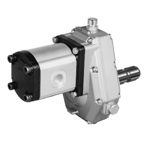
Understanding Hydraulic Gear Pump System Components

Operational efficiency of hydraulic gear pumps is attributed to the presence of various constituent parts that are important. These main elements include housing, gears, rotors, and inlet/outlet ports. The housing provides structural support as well as act as a container for the hydraulic fluid while the gears move the fluid through the pump. These interlocking gears create a hermetically sealed space that permits controlled fluid movement from an entry port to an outlet port. On the other hand, rotor fixed on a motor propels these gears and facilitates their pumping action.
Hydraulic gear pumps may also integrate diverse seals, bearings and wear plates in addition to these core components so as to improve performance and durability. Seals are necessary for avoiding leaks and maintaining system pressure while bearings hold rotating elements ensuring smooth operation with minimum friction. Which protects the innermost pump surfaces from scratching due to extended use, thereby increasing its operational life span. All these components should work together harmoniously to ensure good performance and efficiency in a hydraulic gear pump system.
Relief Valve & Gear Pump Systems
The safety valve is essential about overpressure conditions within hydraulic gear pump systems since it has an important part towards this end. This component must always be present because without it, pumps together with related machinery would be damaged by abnormally high pressure build up, causing sealing failure and loss of lubrication properties, hence leading to unstable operating conditions or equipment wreckage. Upon reaching pre-set limit values, the relief valve used here allows bypassing fluid back through the tank instead of damaging other components, such as hoses, or forcing cylinders apart.
In terms of technical parameters, some specifications which are commonly evaluated for relief valves are:
- Pressure Setting: This is the maximum pressure level at which the relief valve is designed to open. Common settings for hydraulic systems may range from 1500 psi to 3000 psi, depending on the specific application type or system design considerations.
- Flow Rate: This parameter defines the amount of hydraulic fluid that can bypass the system once the valve opens. Normal flow rates vary but are often in the 10-50 gallons per minute (GPM) range for most hydraulic systems, depending on application requirements.
- Response Time: The time it takes for the relief valve to react and open upon reaching the set pressure is crucial for system safety. Ideally, response time should be less than one second, allowing a fast pressure release to prevent damage.
- Material Compatibility: The relief valve materials must be compatible with the hydraulic fluid in use to minimize corrosion and ensure longevity. Common materials include stainless steel and brass because they resist many types of hydraulic fluids well.
Combined with this particular item’s overall intended function within a given hydraulic system, these factors will help ensure that it operates within appropriate limits while still providing necessary protection against failure, such as breakdown or damage resulting from overheating caused by improper selection.
Compatibility of Electric Motors and Efficiency with Gear Pumps
When considering the compatibility of electric motors and efficiency with gear pumps, it is important to consider various factors such as power ratings, torque characteristics, and operational speed ranges. Power rated in horsepower (HP) or kilowatts (kW) should match the horsepower requirements of the gear pump for optimal performance. Furthermore, the motor’s torque output at the desired operating speed must correspond to the specifications by the gear pump, as low torque may result in underperformance or mechanical failure.
Efficiency is another key area where electric motors could reach efficiencies over 90%, thus highly impacting the total energy consumption of the hydraulic system. Further enhancing efficiency by cutting down on energy losses resulting from excessive heat generation and component wear is achieved when the motor’s speed matches that of the pump’s optimum operating range, which is often between 1000 to 1800 RPM in industrial applications. Similarly, considerations regarding motor type – induction vs synchronous motors – can also affect performance outcomes depending on specific application needs. Lastly, proper alignment between the electric motor and gear pump minimizes vibration and wear to ensure long-term reliability in a hydraulic system.
The Role Played By Hydraulic Reservoir in Gear Pump Systems
The hydraulic reservoir is important in gear pump systems because it serves as a storage tank for hydraulic fluids needed for operation throughout the whole hydraulic circuit. It contains a backup source that allows consistent functioning even during temporary conditions when there might be changes in demand. In addition, adequate volumes of hydraulic fluid provided by the reservoir maintain stable fluid pressure and flow rates essential for optimal pump functioning.
In addition, because hydraulic fluid is circulated through this system, absorbing heat generated from gears during their process, it enables cooling that helps extend the life cycle of both pumps and this fluid itself. Additionally, this settling tank enables contaminants and particulates to settle out, thereby preserving integrity and protecting worn-out sensitive components from wear. Therefore, correct sizing and positioning of hydraulic reservoirs play a critical role as they influence gear pump systems’ general performance and reliability.
Hydraulic Gear Pump Cavitation: Causes and Solutions

Cavitation in hydraulic gear pumps occurs when the local fluid pressure drops below the hydraulic fluid’s vapor pressure, leading to the formation of vapor bubbles. This could result from several reasons, such as low fluid supply, high fluid temperature rise, or excess flow restriction within the suction line. The collapse of these bubbles creates impact waves that can cause significant damage to pump parts, thus leading to reduced efficiency and eventual breakdown.
Mitigating cavitation involves running a pump within appropriate limits specified by its manufacturer. Net Positive Suction Head (NPSH) should also be maintained at all times through siting the pump closer to the reservoir and minimizing suction line losses due to friction. Furthermore, maintaining hydraulic fluid at optimum temperatures prevents the development of vapor. Regular system maintenance operations should be carried out with a keen eye for potential blockages or leaks that may be causing cavitation within it before they result in severe damage. By addressing what brings about cavitation and putting in place robust systems, operators significantly improve the life expectancy and dependability of hydraulic gear pump systems.
Signs for Cavitation in Hydraulic Gear Pumps
Cavitation in hydraulic gear pumps is associated with several signs that point towards other problems within your system.One of these is an increased noise level characterized by loud rumbling or grinding as these vapor bubbles burst apart. Another indication is that this device might have lowered performance whereby lower rates are achieved while measuring the flow rate in addition to seeing a lot more fluctuation regarding pressures. Furthermore, vibrations on pump components can lead to abnormal wear. Telltale signs involving foaming or aeration may present themselves when inspecting hydraulic fluids since they may indicate presence of cavitations.These cavitation symptoms allow one enough time to avoid extensive damage, thereby guaranteeing efficient operation for any given hydraulic gear pump.
Preventing Cavitation in Gear Pumps
A number of technical strategies must be implemented to prevent cavitating gear pumps adequately. First, it is important to ensure that there is enough inlet pressure. To minimize the likelihood of cavitation, the Net Positive Suction Head Required (NPSHr) should be less than the Net Positive Suction Head Available (NPSHa). A good example of NPSHr is roughly 1.5 times greater than NPSHa to maintain maximum performance.
Secondly, this can also be prevented by cooling down the hydraulic fluid because increasing temperatures reduce fluid density and cause vapor pressure to rise thus making it more prone to developing vapour. Keeping the temperature below critical threshold of the fluid which ranges around 40°C renders huge gains in terms of performance and stability for most applications.
Furthermore, using suction lines with wide diameters would minimize frictional losses which result in higher fluid velocity and pressure at pump entrance. Application inline filters with properly designed mesh are essential for avoiding any form of cavitation during operation.
Finally, constantly monitoring system parameters such as flow rate or pressure particularly sudden changes help operators identify early signs of caviation before they become severe.In order to comply with operational rules and enhance gear pump’s lifespan regular checks on systems performance need to be conducted
Gear Pump Maintenance Techniques for Reducing Cavitation.
Maintenance practices should aim at system integrity and component functionality to lessen the chances of cavitation in gear pumps. The suction lines must be inspected to discover any blockages or losses that interfere with inlet pressure. In addition, all packings and seals need to be carefully scrutinized for signs of wear or injury since integrity is important in maintaining proper pressure levels.
Also, scheduled maintenance should involve cleaning and replacement of inline filters to provide continuous fluid flow while minimizing debris accumulation capable of decreasing efficiency. It is therefore vital to keep an eye on hydraulic fluid condition – it should be checked for contamination levels while any sign of degradation will necessitate its immediate replacement in order to uphold thermal stability.
Moreover, enforcing regular checks on pump mounting and alignment can avoid vibration-related problems leading to cavitation. Properly aligning the pumps helps reduce unnecessary strain that falls on bearings and gears, thus improving operational dependability while extending equipment life span.
Advanced Troubleshooting Techniques for Gear Pump Issues

To troubleshoot gear pump issues, one must approach them systematically by combining diagnostic techniques and practical interventions. A good place to start is to assess the pump’s performance characteristics, such as flow rate, pressure, and temperature, to determine where these values deviate from the norm. By making a deep dive into the pumps’ historical operational data, one might find patterns indicative of repetitive failure.
Vibration analysis tools can diagnose mechanical problems such as misalignment or bearing failure. Moreover, acoustic emission analysis can reveal early signs of cavitation or cavitation-induced damage, enabling prompt intervention. It is also essential to check for air leaks within the hydraulic system or fluid quality deterioration because this could aggravate gear pump issues.
If initial inspections have failed to establish the source of a problem, further invasive examination, such as disassembly or scrutinizing internal components, may be required. Look for wear patterns on gears and shafts or pitting while inspecting each bearing for signs of overheating or failure. In addition, it is important to document findings during the troubleshooting process so that future adjustments can be made efficiently.
How To Analyze Hydraulic Fluid Quality For Gear Pumps
When evaluating hydraulic fluid quality for gear pumps several important things need consideration in order to enhance both the life span and efficiency of your pump system. Firstly, you should analyze how viscous your hydraulic fluid is. The fluid’s viscosity directly affects hydraulic systems’ efficiency, often leading to increased friction and power loss associated with higher-viscosity fluids. generally speaking, using V.I. will help you understand how viscosity changes with temperature changes.
After that inspection needs be done on contamination levels. This consists of particulate contamination levels and water content that can severely affect the integrity of hydraulic fluid at large scales. By that, I mean it really undermines its extensive applications within mechanical systems, especially when not detected early enough through standard sampling methods like particle count tests and spectroscopic analysis.
Additionally, the thermal stability of the hydraulic fluid should be checked. Thermal stress can cause fluid degradation, generating sludge and varnish that affects pump operation. Checking for oxidation products and acidity as measured by Acid Number (AN) regularly serves as indicators of fluid deterioration.
Finally, a comprehensive fluid maintenance program is also important to determine how often fluids need to be replaced based on results obtained from regular quality assessments. This approach is proactive not only in enhancing the efficiency of gear pumps but also prevents other operational challenges due to worn-out hydraulic fluids.
Monitoring Operating Temperatures in Gear Pumps
Monitoring operating temperatures in gear pumps is crucial for their reliability and efficiency. Temperatures must be kept within prescribed limits to avoid thermal breakdown of hydraulic fluid and reduce wear on pump components. High operating temperatures imply a lack of lubrication, thick oil, or worn-out parts, among other things, which may result in premature mechanical failure.
Placing temperature sensors at strategic points within the pump system allows for instantaneous measurement. Feedback loops with control systems that automatically adjust operations so as maintain optimal temperatures are examples here. In addition, conducting periodic reviews on temperature data can facilitate early identification of trends and anomalies and thus prompt preventive maintenance measures. Heat exchangers or flow circulation systems may be installed if overheating occurs more frequently than normal. In conclusion, a detailed temperature management protocol will greatly increase the endurance and effectiveness of gear pumps over time.
Assessing Compatibility and Wear of Gear Pump Components.
When considering the compatibility and wear of gear pump parts, it is important to take into account their material properties, operating environment, and fluid type being used. To avoid adverse effects that may cause accelerated wear or failure, compatibility should be checked by comparing the chemical composition of hydraulic fluids with those of materials used in the manufacturing of gears, bearings, and seals.
It is crucial to conduct regular inspections aiming to detect any changes in dimensions, surface roughness or pitting as signs of wear and tear. Ultrasonic testing or visual inspections can be carried out to identify early warning signs for these indications. Additionally, pressure fluctuations, as well as efficiency ratios, are some of the parameters that can be monitored in order to determine how well the pump is performing. Analyzing data on operational conditions vis-à-vis wear patterns through big data analytics encourages more predictive maintenance strategies improving component lifecycle management. To sum up, systematic evaluation of compatibility and wearing offers peak performance and longevity of gear pump systems.
Reference sources
- Machinery Lubrication
- Source: https://www.machinerylubrication.com/Read/31064/troubleshooting-hydraulic-pumps
- Summary: Contamination can come from various sources, emphasizing the need for vigilance and responsible practices in hydraulic pump troubleshooting.
- Womack’s Guide
- Source: https://www.womackmachine.com/data-sheet/troubleshooting-tips-for-hydraulic-pumps/
- Summary: Expert tips provided for troubleshooting hydraulic pump issues to ensure reliable performance within hydraulic systems.
- Supreme Integrated Technology
- Source: https://supremeintegratedtechnology.com/blog/hydraulic-pump-problems
- Summary: Detailed guide on identifying and troubleshooting common hydraulic pump problems, offering practical solutions for readers.
Frequently Asked Questions (FAQs)
Q: What are the common symptoms of a failing hydraulic gear pump?
A: Common symptoms include unusual noises, decreased flow or pressure, overheating, and fluid leaks.
Q: How does cavitation affect hydraulic gear pumps?
A: Cavitation can cause damage to the pump components, leading to pitting, reduced efficiency, and eventual failure.
Q: What is the impact of hydraulic fluid viscosity on gear pump performance?
A: Proper hydraulic fluid viscosity ensures efficient lubrication and prevents excessive wear, overheating, and reduced pump life.
Q: How can I identify air ingress issues in a hydraulic gear pump system?
A: Air ingress is often identified by foamy hydraulic fluid, noisy operation, and inconsistent pump performance.
Q: What steps should I take if my gear pump is overheating?
A: Check for proper fluid levels, ensure adequate cooling, inspect for clogs in the cooling system, and verify that the pump is not overworked.
Q: How do I detect leaks in a hydraulic gear pump?
A: Look for visible fluid on the pump exterior, check seals and fittings, and use dye testing if necessary to locate the source of leaks.
Q: What causes inconsistent flow rates in hydraulic gear pumps?
A: Inconsistent flow can be caused by air in the system, blockages, worn components, or incorrect system setup.
Q: What maintenance practices help prevent cavitation in hydraulic gear pumps?
A: Regularly check and maintain proper fluid levels, use the correct fluid viscosity, and ensure the system is free of air and contaminants.
Q: How do I assess the wear and tear on my hydraulic gear pump components?
A: Inspect the pump regularly for signs of wear on the gears, shafts, seals, and housing. Look for unusual wear patterns and replace components as needed.
Q: What is the role of the relief valve in a hydraulic gear pump system?
A: The relief valve protects the system from excessive pressure, which can prevent damage to the pump and other components.