Hydraulic gear pumps are integral components in modern machinery, powering a wide range of industrial and mobile applications through efficient fluid transfer. These pumps rely on the precise interlocking of gears to generate flow and pressure, ensuring reliable performance in even the most demanding environments. This guide is designed to provide a detailed exploration of hydraulic gear pumps, including an in-depth look at their components, working principles, and functionality as illustrated through comprehensive diagrams. Whether you’re an engineer, technician, or machinery enthusiast, this article will equip you with a clear understanding of how these pumps operate and why they are critical in systems that depend on hydraulic power.
What is a Hydraulic Gear Pump and How Does It Work?

Basic Gear Pump Components
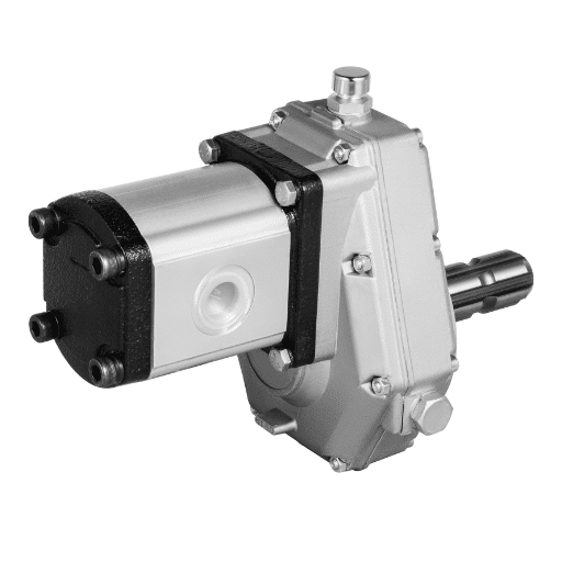
The components of a hydraulic gear pump include a housing, two meshing gears, a drive shaft, and end covers. The housing, a cast iron or aluminum alloy, encases the entire mechanism for strength while also ensuring that no hydraulic fluid escapes the system. The driving gear and driven gear, which perform fluid displacement alongside flow creation, are crucial constituents of the hydraulic system’s meshing gears.
An external power source, for example, an engine or electric motor, is able to rotate the driving gear due to a drive shaft that is linked to transferring mechanical energy. This causes the pump to create suction at its inlet with the subsequent intake of hydraulic fluid. Gears will trap fluid between their teeth as well as the inner surface of the housing and transport it to the outlet. End covers with precise tolerances reduce leakage while improving volumetric efficiency by maintaining an adequate seal.
As a hydraulic gear pump, these components allow proper flow and pressure consistency to be achieved which makes it applicable in numerous hydraulic systems. In comparison to other assembly types, this configuration provides increased reliability and ease of upkeep without compromising on the level of efficiency vital to agricultural and industrial machinery.
How the Pump Operates in a Hydraulic System
The operation of a hydraulic gear pump involves generating flow in the pump by the interaction of the gears in the pump cavity. During gear rotation, fluid is pulled from the reservoir into the pump through an inlet port. This is possible because the teeth of the gears are meshing and creating a void which allows the fluid reservoir, under atmospheric pressure, to push the fluid into the pump. The fluid moves to the outlet port through the periphery of the gear’s teeth.
The rotation of the gears continuously pumps the fluid, thus converting the mechanical power into hydraulic power. A precise design of the gear ensures that there will be little leakage on the flow path. Fluid then leaves the pump at the outlet port with higher pressure, hence it can be supplied to other devices in the hydraulic circuit, like the actuators or valves. The amount of pressure created is related to the system load that the pump provides, only flow, not pressure.
Due to their systematic operation principle, gear pumps are essential components in the transfer of hydraulic energy. Their design is simple and cost effective which is why they are integrated into a large number of systems which need set flow rates with moderate pressure for effective functioning in industrial, mobile and agricultural systems.
Flow of Hydraulic Fluid in a Gear Pump
The flow of hydraulic fluid within a gear pump starts as the drive gear lifts and engages with the driven gear. This engages suction at the inlet port, which then pulls the hydraulic fluid from the reservoir. The fluid is contained between the gear teeth and the pump housing and is subsequently moved to the outer side of the pump as the gears rotate.
While the gear teeth are partially immersed, the tooth grinding guarantees that there will be no interruptions at any time in the flow of liquid. The fluid is transported to the outlet port, where the pressure builds because of the throttling effect from decreased flow of the downstream parts, which may be actuators or valves. The mechanical work gets performed with the directed pressurized fluid in the hydraulic system. The high pressure leads to the tight clearances along with the strong structure of the gears, which reduces internal leakage, fortifying efficiency and maintaining the desired flow.
A gear pump, unlike other pump types, makes use of these strengths with its simple mechanism and repeats use for hydraulic systems while relying on a single variable for monitoring the pump output, performance controlling. Nonetheless, it is uniquely ideal for moderate flow control methods and steady pressure output. From its simplistic design comes newfound ease of maintenance, raising its trustworthiness during use and making it favored across industries like construction, manufacturing, and agriculture.
How Does Pump Displacement Affect Performance?

Understanding Positive Displacement in Pumps
Positive displacement pumps work by capturing and controlling the flow of a specific amount of fluid through a system to ensure a constant rate of movement. This is done with mechanical parts like gears, pistons, and diaphragms that make enclosed chambers which trap and move fluid. Unlike centrifugal pumps that depend on fluid speed or dynamic pressure, positive displacement pumps offer a constant flow rate regardless of changes in system pressure or fluid thickness. This property makes them suitable for applications where precise fluid measurements need to be taken. Positive displacement pumps are particularly useful when strict charging or measuring of liquid in high-pressure or high-viscosity solutions is needed.
An example of this is the pumping of heavy oils, which are considered high-viscosity fluids. Also known as syrup, these fluids show a very high difference in exerted forces when spu,n so having a set flow meets the requirement for constant flow rate. Even with these limitations, positive displacement pumps perform exceptionally, surpassing centrifugal pump designs in terms of risk-free bubble formation. Positive displacement pump designs use multiple sealing pieces that easily minimize leakage, thus giving these positive pumps a high volumetric efficiency, which is a defining trait of such pumps.
Moreover, modern advancements in materials and manufacturing processes have enhanced the polymetric positive displacement pumps to safely manage corrosive chemicals, abrasive slurries, or sensitive biological fluids with greatly reduced wear and tear.
The Role of Displacement in Pump Performance
Displacement is a key factor affecting the efficiency, accuracy, and reliability of a pump’s operations. Positive displacement pumps are specifically tailored for the movement of liquids. Each cycle is designed to pump a set volume, which makes these pumps ideal for situations needing precise control of fluid flow, independent of the system’s pressure. This trait guarantees increases in consistency and further reduces the chances of pulsation in processes that rely on steady flow.
The flow capacity of a pump is categorized as the product of its displacement per cycle multiplied by its operating speed. This volume is directly affected by displacement which for instance rotary vane or diaphragm pumps often deliver high volumetric accuracy due to their effective sealing mechanisms as internal leakage is reduced. In pharmaceuticals or chemical manufacturing, some industries become increasingly sensitive towards small variances as the quality of products become adversely impacted during fluid handling.
Correct displacement devotion is useful for the efficient reduction of energy consumption. Misaligned sizing or operating conditions beyond the intended capacity of the pump can bring about secondary issues. With advances in CFD and engineering materials, modern designs now allow for flexible operation across diverse sectors from oil and gas pipelines to food grade applications.
Comparing Variable Displacement Pumps and Fixed Displacement Pumps
The two fundamental types of pumps, variable displacement and fixed displacement, each have unique capabilities and applications. A fixed displacement pump provides a specific flow rate for each revolution regardless of the system pressure or load demand. This makes the pump ideal for use in systems where a constant flow is needed, such as in the hydraulic systems used in heavy machinery or in industrial operations. However, these types of pumps are inflexible in design and energy inefficient in systems where flow or pressure needs calibration.
A variable displacement pump, on the other hand, offers greater flexibility; it can change its flow rates by changing the internal structure of the pump itself, which allows it to respond to different system needs. This greatly enhances energy efficiency since only the amount of hydraulic fluid needed for the work being done is delivered, thus reducing power loss. Precision control and variable output applications, such as in automotive systems and advanced manufacturing equipment, use these types of pumps. While beneficial, they tend to be more complex and costlier due to the intricate design and control mechanisms of the pump.
In my experience, selecting between these two types of pumps relies mainly on the functional needs and preferences of the system. Thinking about situations that place importance on control ease, reliability, as well as steady flow without intricacies, I would consider employing fixed displacement pumps. On the other hand, in ever-changing surroundings where energy conservation, exactness, and flexibility are primary, the most suitable option is variable displacement pumps. Considering all these aspects helps make the right decision on the type of pump that offers the best efficiency concerning the operational environment of the system.
What Are the Different Types of Hydraulic Pumps?

Overview of Internal Gear Pumps
Like other kinds of positive displacement pumps, internal gear pumps are well known for their effectiveness and dependability in managing fluids, even those with high viscosity. Their construction comprises two meshing inter-gears, a larger outer gear with internal teeth, and a smaller inner one that rotates within the larger one. The rotation of these gears enables a fluid cavity to be carved, which gets trapped as the gears turn, providing fluid under pressure without unprecedented turbulence. This belief is backed by data that states internal gear pumps support pressure up to around 3000 PSI or more.
Additionally, external gear pumps have certain shortcomings that internal gear pumps overcome, such as their compact design, which allows them to be used in confined areas with the guarantee of superior performance. They also operate with great volumetric efficiency, which makes them perfect for chemical processing, automotive lubes, and hydraulic power units. Another area where internal gear pumps outshine their counterparts is temperature tolerance, with many able to run in harsh condition between -40 to 400 Fahrenheit based on construction materials used.
Due to the minimal amount of moving parts, the internal gear pumps have an uncomplicated maintenance process which results in reduced downtime and an increased lifespan of components. Moreover, the capability of the pump to deal with fluids sensitive to shear without deterioration is an added advantage, particularly in sectors needing careful fluid management.
Differences Between Gear Pump, Vane Pumps, and Piston Pumps
The distinguishing characteristics of gear pumps, vane pumps, and piston pumps can be summarized as follows: Gear pumps are uncomplicated, rugged, and best utilized in low-pressure settings; vane pumps offer a more uniform flow and operate with variable stroke control; and piston pumps offer high efficiency, high pressures, and are best suited for tasks which require high accuracy.
Here’s a concise table summarizing the key differences:
| Aspect | Gear Pump | Vane Pump | Piston Pump |
|---|---|---|---|
|
Operation |
Gears |
Sliding vanes |
Reciprocating pistons |
|
Flow Type |
Fixed |
Fixed/Variable |
Fixed/Variable |
|
Pressure Range |
Low-Medium |
Medium |
High |
|
Performance |
Moderate |
Smooth flow |
High |
|
Upkeep |
Low |
Moderate |
High |
|
Usage |
Low-pressure |
Lubrication |
High-precision |
|
Expense |
Low |
Moderate |
High |
Understanding Lobe Pumps and Their Applications
The lobe pump is a type of positive displacement pump that is designed to be viscous sensitive while ponying minimal shear to the medium, which means it does not harm the fluid being pumped. It contains rotating lobes that mesh with each other within the boundaries of a pump case. They work without touching each other, rotating and forming sealed cavities which create a partition. Due to the construction of the lobe pump, it can be said that the medium is handled softly without harming the flow rate. Consistency in the flow rate is achieved for both volume and speed. Because of their flexibility and convenience, lobe pumps can be used in many industries. Let’s see the five most important applications for a lobe pump:
- Food and Beverage Industry: Due to exceptional hygienic features and high viscosity pumping without degradation, lobe pumps are ideal for transferring food products and sauces.
- Pharmaceutical and Biotechnology Processes: Low shear management makes these pumps perfect for transferring delicate or sterile materials during a pharmaceutical production making sure the product is not damaged and is up to the hygiene standards.
- Chemical Processing: For processes where precision and durability are paramount, lobe pumps are suitable as they can handle corrosive and viscous chemicals.
- Cosmetics Manufacturing: Due to low shear and practically no damaging of sensitive or viscous materials like creams, lotions and gels, lobe pumps are best suited for cosmetics production applications.
- Wastewater Treatment: Lobe type rotary pumps are used for sludge and slurry handling operations in wastewater treatment plants because they can manage high viscosity and solid-slurries effeciently.
Their efficacy and versatility in various industries affirm the role of lobe pumps in both common and niche uses.
How to Optimize Hydraulic Pump Performance?

Factors Affecting System Pressure and Flow
Many different and interconnected factors affect the performance of a hydraulic pump. It is critical to know these elements for optimizing efficiency and increasing the life span of the equipment. The following factors are of primary importance:
- Fluid Viscosity: Hydraulic fluid viscosity greatly affects the system pressure and flow rate. Too much viscosity creates too much resistance in the system which leads to inefficiencies and heating. On the other hand, a fluid with low viscosity may not lubricate sufficiently and could cause early wear on components.
- Temperature Stability: Ram temperatures influence a fluid’s viscosity along with its compressibility. Cavitation, pressure losses, and other critical systems performance issues may arise due to extreme temperature conditions. Effective cooling systems or thermal stability solutions design can address many of these challenges.
- Pump Speed and Efficiency: Rotational speed affects a pump’s output flow and electric motor induced system pressure. Going too fast can cause volumetric efficiency and cavitation issues whereas going too slow won’t be able to meet system demands. Adjusting the speed to the requirements of specific applications being served is paramount.
- System Leakages: Both internal and external leaks on hydraulic circuits greatly contribute to pressure loss, decline in efficiency and increased energy consumption. The result is high operating costs. Regularly scheduled maintenance along with timely inspections is essential.
- Contaminant Control: Particles or water as a contaminant in the hydraulic fluid can impede flow within the system as well as damage important parts over time. This underscores the importance of employing stringent fluid cleanliness policies, which include high-efficiency filtration systems and frequent fluid quality audits and maintenance.
- Load Demand Variations: Flow and pressure requirements are directly influenced by the system’s load demand. The use of variable displacement pumps or pressure compensating controls that allow for economy of range can optimize a design’s performance for a wider range of operational conditions.
Addressing these factors allows an operator to improve reliability, lower costs, and prolong the life using systematic approach. Strategic design tailored alongside routine checks and maintenance ensures reliable and adaptable hydraulic pump performance throughout varying situations or conditions.
Importance of Flow Control and Pressure Drop
Control of flow, as well as the flow´s resistance against pressure drop, are extremely important aspects to monitor in a hydraulic system given that they affect the system’s efficiency, stability, and energy use. System demand-driven flow rates can also be met with proportional valves, flow regulating valves and orifice plates.
As fluid moves through various system components such as pipes, fittings, and valves, there is a loss in pressure known as pressure drop. If not controlled, energy efficiency and system performance deteriorate significantly. In addition, the rate of heat generation, and therefore component wear, is increased, which reduces the lifespan of hydraulic components. The rate of pressure drop can be minimized by analyzing the diameter of the pipes in use, their length, the viscosity of the fluid, and the flow speed. When equipment selection is done correctly, these factors can be balanced to maximize system performance and the life of the system components.
Now we can utilize complex computer models and simulations to study flow dynamics and predict pressure drop under different operational situations. With these tools, engineers can much more effectively and accurately improve system designs by correcting identified inefficiencies before deployment. Ultimately, controlled flow with a minimized pressure drop helps improve energy efficiency and lowers the maintenance costs, as well as extending the lifecycle of the system’s hydraulics.
What Are the Critical Parts of a Hydraulic Gear Pump?

Understanding the Role of Driven Gear and Outer Gear
Both the driven gear and outer gear in a hydraulic gear pump are central structures, and both serve specific purposes in a hydraulic gear pump. The driven gear is mechanically coupled to a power source and rotates while directly feeding motion to the outer gear’s screw. In this coordinated motion, a displacement chamber is formed within the grooves of the gears and their casing, where hydraulic fluid can be enclosed and moved inflow channel to the pump’s efflux.
The displacement volume’s capture and release depend on the driven gear’s effectiveness in maintaining particular axial shifts and combating slippage and friction energy losses. The back flow and pressure imbalance control is handled by the trim seal together with the driven protrusions. The role of the outer gear is to keep the pre-defined angle between the shafts as well as to maintain the closed chamber containment. Recent innovations in materials technology help integrate far more wear-resistant and durable nonferrous metals than before, thus shifting the mid-life servicing time greatly.
Understanding the relationships among the driving gear, driven gear, and hydraulic drives enables the engineers to refine the gear shape and the case modification to attain greater volumetric and mechanical efficiencies. This understanding is critical for system design in more severe cases, for example, in construction, aerospace, and manufacturing, where dependable hydraulic performance is needed over a range of speeds and loads.
The Function of Pump Housing in Maintaining Integrity
The pump housing is sophisticated enough to encase the internal parts of a gear, piston or vane hydraulic pump and it can hold all of these components in place while enduring extreme amounts of stress and still functioning with great efficiency. As a result, a pump’s internal mechanisms will always be protected. When a hydraulic system is used, the pump housing will also experience great amounts of thermal and mechanical stress due to varying temperatures.
To further enhance the function of the pump, manufacturers now utilize stronger materials such as aluminum alloys, ductile iron, or polymer composites, which have high strength and low weight. In addition to these factors, the materials have excellent thermal conductivity and corrosion resistance, which makes them perfect for specialized pumps. Moreover, the pump seals and gaskets reduce volumetric efficiency, which means the housing must be designed in a way that can withstand deformation during intense stress.
New designs help pumps and other hydraulic devices endure even greater loads. With these alterations, as well as other simple changes such as advanced CNC machining to reduce offset tolerances, the efficiency of the device improves. In places where additional durability and performance is essential, these modifications make significant improvements for the systems lifecycle.
Frequently Asked Questions (FAQ)
Q: What is a hydraulic gear pump, and how does it work?
A: A hydraulic gear pump is a mechanical device that converts mechanical energy into hydraulic energy by using two gears. The pump consists of two gears that mesh together to create a flow of hydraulic oil, which is then used to power hydraulic equipment. This process allows the pump to deliver hydraulic pressure within the hydraulic system.
Q: What components are typically found inside the pump?
A: Inside the pump, you will typically find two main gears: the drive gear and the idler gear. The pump chamber is where these gears rotate to move hydraulic oil from the pump inlet to the pump outlet. Additionally, pumps may include a relief valve and control valve to regulate pressure and flow.
Q: How do the pump inlet and pump outlet function?
A: The pump inlet is where hydraulic oil enters the pump chamber. The rotation of the gears creates a vacuum that draws in the hydraulic oil. As the gears continue to rotate, the oil is pushed towards the pump outlet, where it exits under pressure to perform hydraulic operations.
Q: What is the role of the relief valve in a hydraulic gear pump?
A: The relief valve is a critical component that helps prevent excessive pressure build-up within the hydraulic system. It allows the pump to safely release excess hydraulic pressure by redirecting oil flow when the pressure exceeds a predetermined level, thus protecting the pump and other components.
Q: How is pump flow measured in a hydraulic gear pump?
A: Pump flow is typically measured in gallons per minute (gpm). This measurement indicates how much hydraulic fluid the pump can deliver per minute, which is crucial for determining the efficiency and capability of the pump in various hydraulic operations.
Q: Can a hydraulic gear pump be used in a gear pump circuit with two pumps?
A: Yes, a gear pump circuit can include two pumps to achieve higher flow rates or to provide redundancy in hydraulic systems. By using two pumps, one can ensure continuous operation even if one pump needs to be taken offline for maintenance.
Q: What factors affect the life of the pump?
A: The life of the pump can be affected by various factors, including the quality of hydraulic oil, the hydraulic fluid level, the presence of contaminants, and the overall maintenance of the hydraulic system. Using high-quality hydraulic oil and maintaining proper fluid levels can significantly extend the life of the pump.
Q: How does the directional control valve influence the hydraulic pump’s function?
A: The directional control valve is responsible for directing the flow of hydraulic fluid to different parts of the hydraulic system. It plays a crucial role in determining the direction of movement in hydraulic cylinders and other components, thereby controlling the hydraulic operations.
Q: Why is it important to maintain a high-quality hydraulic oil in the system?
A: Maintaining high-quality hydraulic oil is essential because it reduces pump wear, prevents contamination, and ensures efficient operation. Good quality oil helps in extending the life of the pump and maintaining optimal hydraulic pressure and performance within the system.