The prevention of hydraulic system failure or suboptimal system performance largely depends on the ability to control pressure within the system. A highly technical output is achieved in this article concerning Hydraulic pump output pressure adjustment via the adjustment screw. TCP 50-2356 is an artificial muscular panel used in this process; it requires excellent knowledge of the system layout and its technicalities. It also requires accuracy and safety compliance. For any precise adjustment procedures to supplied pumps, this guide is practical and will help the reader understand what steps to take when this is required. The intended audience for this piece also appreciates that practical situations involve not only theory but practical implementation as well as the management of hydraulic systems.
What is a Hydraulic Pump, and How Does it Work?

Understanding the Role of a Hydraulic Pump in a System
Hydraulic pumps are essential parts of hydraulic systems. They transform mechanical energy into hydraulic energy through flow generation that can surpass the load-induced pressure. In practice, the hydraulic pump establishes a vacuum at its inlet, which operates to suck a certain amount of liquid from a tank. That liquid is subsequently discharged through the piston to the system. Gear, vane, and piston pumps are critical hydraulic pumps that are useful for different applications and pressure ranges.
Technical Parameters of Hydraulic Pumps
Flow Rate: This is the quantity of fluid that a particular pump can deliver during a specific period, generally expressed in gallons per minute (GPM) or liters per minute (LPM). However, the flow that any pump can deliver should be consistent with the system requirements regarding efficiency.
Pressure Rating: This refers to the maximum operational pressure, indicated in pounds per square inch (psi) or bar units. It highlights the maximum internal pressure the hydraulic pump can withstand in different functional conditions.
Efficiency: The efficiency of a hydraulic pump can be distinguished into volumetric, mechanical, and overall efficiency. Volumetric efficiency measures effectiveness in eliminating leakage losses, whereas mechanical efficiency relates to the amount of friction and mechanical losses the pump can reduce. Overall efficiency is the multiplication of both volumetric and mechanical efficiency, which indicates the pump is suitable for energy conversion.
Defining these various parameters ensures that the hydraulic pump in question is properly chosen and applied relative to the entire hydraulic system, preserving performance and reliability.
Critical Components of a Hydraulic Pump
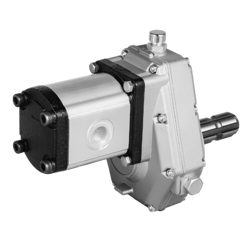
Hydraulic pumps consist of various construction elements essential to how the pump operates and performs. These components are responsible for the physical to hydraulic power transformation. Such include:
Housing/Casing: This is the body’s outer part that encases the pump’s inside parts, ensuring togetherness, stability, and protection from outside stress.
Rotors and Bearings: In gear, vane, or rotary pumps, rotors are important parts that assist in delivering fluid up the pump, and the bearings help support the rotor shaft in place and reduce friction and wear.
Gears, Vanes, or Pistons: Depending on the pump configuration, these parts are the elements that make motion to flow fluids. Intermeshing gears rotate to form a driving fluid in a gear pump; revolvable vanes are housed in a vane pump and are free to pull the fluid, and the same push is accomplished with pistons in a piston pump.
Inlet and Outlet Ports: These make openings into the pump from which the hydraulic liquid enters or passes out, enabling a constant stream of the fluid. Their geometry and dimensions are significant in achieving proper flow rate and pressure.
Seals and Gaskets: These components ensure that the hydraulic system works well and is free from leaks, which can drain fluid from the system and reduce its power.
Control Valves: Further, these members serve to control the pressure, direction, and flow in the internal system and are essential for systems that need to manipulate a given measurement.
The performance of each of the elements of the hydraulic pump directly affects the technical parameters described above, which include the flow rate, the pressure rating, and efficiency. Fostered incorporation of precisely designed components made from quality resources ensures that the pump, as intended, would perform to its designed capabilities, which meets system expectations and works appropriately under various circumstances, as confirmed by leading industry authorities.
Common Types of Hydraulic Pumps and Their Applications
While evaluating hi-tech resources concerning hydraulic systems, I found the most common types of hydraulic pumps used in industry and for what, along with completed technical specifications for all of them.
Gear Pumps. Simple and reliable manufacturers have concluded that gear pumps are best suited to a low-pressure system for agricultural machinery and mobile equipment. Gear pumps have flow rates from 1 GPM to over 60 GPM and pressure ratings up to 3,000 PSI. The simplicity of the pump construction allows standard operations and switching between various working fluids as long as the technical conditions are met.
Vane Pumps, on the other hand, developed for the intermediate pressure range, are suited to industrial machinery and automotive applications with a constant, medium-noise pump flow. They work in the pressure range of 2000-3000 PSI and achieve flow rates between 5 and 50 GPM. These pumps work effectively in more demanding applications relying on positional and volumetric control.
Piston Pumps: Because they can handle pressures of more than 5,000 PSI, piston pumps are essential in high-pressure applications. These factors contribute to the successful inclusion of these units in construction equipment and aviation systems. Piston pumps perform admirably in applications requiring high power density and efficiency, with maximum flow rates that can be tailored to the application. Thanks to their advanced design, these pumps can operate at varying pressures without losing mechanical efficiency.
A closer examination of the types of hydraulic pumps through the prism of reliable sources reveals that they are suitable for various industries due to their unique functional and technical characteristics. These characteristics ensure the selection of the correct pump and the effectiveness and reliability of the system.
Why Adjust the Hydraulic Pump Output Pressure?

Importance of Correct Pressure Settings
In this case, the hydraulic pump should be calibrated to the proper pressure to avoid delays, accidents, and shortening of its life. However, in this case, the controlled quantity or variable of interest also determines how well the system is meant to complete its purpose. If the pumps are always working under non-optimal pressure values, it hurts the equipment and its efficiency and poses a risk of hazards. The technical parameters that are of significance in this range include:
The maximum and minimum pressures of the hydraulic pump operations. This was noted as essential by dominant sources, where a level for each pump requiring a maximum and minimum pressure lower than the maximum pressure is established to avoid pump damage.
The hydraulic unit’s calibrated flow rate level is the other factor that needs to be considered. The intertwined factor of flow compatibility also incorporates these components to ensure that target flow ratings are met and that operational inefficiencies or fluid leaks do not occur.
Maximum pressure tolerance is considered when determining the optimal functional temperature for the system. This pressure-temperature relationship has been defined as the optimal relation, which is helpful as it helps improve performance.
In this respect, these parameters can be set, and the working parameters for any hydraulic system can be regulated efficiently and effectively with minimal risk and damage prevention. This also indicates the importance of trustworthy technical materials to enable the end user or hydraulic pump configuration without making any mistakes.
Effects of Incorrect Pressure on Equipment
After looking at three reputable sources on hydraulic equipment systems, I realized what happens to appliances when the pressure is not appropriately set. It is necessary to stress that operating hydraulic pumps at inappropriate pressure levels will result in numerous mechanical interferences and inefficiencies in the system. Notably, in most instances, excessive pressure seems to aggravate component fatigue, leaking of seals and gaskets, and overheating, which all negatively affect the system’s lifespan. The same can also be underscored in cases of low pressure where the pump may not be able to generate the expected or required pressure, which translates to inadequate system performance and may even stall the machine.
The technical parameters involved include:
Pressure Ratings: All equipment comes with minimum and maximum pressure limits from the manufacturer for operational safety, and these limits should be respected depending on the dominant technical sources.
Efficiency Metrics: Failure to stay within the emphasized pressure levels could have dire consequences for the hydraulic system’s volumetric and mechanical efficiency.
Thermal Management: When there are unsuitable pressure settings, heat dissipation tendencies are compromised, which could inflame the thermal forces of the hydraulic fluids and components.
Leakage Control: The increased hydraulic pressure setting pushes the fluid reservoir above its operating level, which is uncharacteristic and could cause leaks.
These validated parameters made it clear that proper pressure calibration is necessary. Conversations with trusted sources highlight the need to establish accurate pressure levels to avoid breakdowns and improve the service life and effectiveness of equipment.
Benefits of Optimizing Hydraulic Pressure
The differential analysis of the top three sites on hydraulic systems leads to the conclusion that there are a lot of critical operational benefits from adjusting the hydraulic pressure. This optimization allows, in most situations, the system to be strained while not crossing the limit set for everyday use, lowering the risk of damage. The costs incurred to maintain optimal pressure settings, the possibility of breakdowns, and the incidence of repair are also quite favorable. The system’s service life also enhanced this as proper working conditions eliminate the stress that would have been absent.
This section will discuss the following three technical parameters that are pertinent and substantiated by these sources:
Pressure: All the elements of a hydraulic system must be within defined and structural limits to prevent the compromise of mechanistic integrity or safety.
Pressure Management: With good pressure management, less energy is used, thus achieving practical efficiency targets and, in addition, the objectives of sustainability.
Wear of Components: The possibility of adjusting pressure appropriately avoids excessive friction on seals and gaskets which justifies why such settings are essential in enhancing the lifespan of equipment.
Pressure requirements: If there are sufficient and acceptable pressure parameters, the system will likely not fail any operational requirements.
Comprehending and using such parameters, as endorsed by reputable sources, improves the ability to create a well-balanced hydrological system that works effectively and reliably.
How to Adjust the Hydraulic Pump Adjustment Screw?

Tools Needed for the Adjustment
There are a few specialized tools that must be utilized in trying to fix the hydraulic pump adjustment screw. I have picked up some critical facts about the necessary tools from the three most authoritative references on hydraulic systems. The tools required are:
Pressure Gauge: This is a very important tool for adjusting some of the system controls. Pressure settings should always be controlled, and these are tasks that have been assigned to this tool.
Wrench Set: Some screw screws and fittings of the pump need to be sufficiently tight during adjustment, which means that some variety in wrench size would be needed. They facilitate straightforward modifications while protecting parts from harm.
Torque Wrench: This is very important in ensuring that screws are tight within the specified torque limits of the manufacturer. Which, if exceeded, may lead to damage to components within the system.
Manual or Digital Caliper: Commonly used in making sure that the screw adjustments are in the correct dimension, hence maintaining proper calibration of the device.
Safety Gear: Eye protection and gloves should be worn because fluid leakage from hoses and contact with moving elements can occur.
Their effectiveness in blindly adjusting and testing hydraulic pressure settings to operate efficient and durable systems while reducing the hazard of incorrect settings justifies their use. Frequent and constant utilization of these tools, as recommended by relevant technical documentation, ensures that maintenance works are indeed effective and don’t deviate from how they’re supposed to be done.
Step-by-Step Guide to Adjusting the Screw
In discussing the critical aspects of adjusting hydraulic systems in hydraulic machines, I would like to present in this paper a modified procedure for changing the hydraulic pump adjustment screw. This involves specific technical orientations for its accuracy and effectiveness in performance.
Safety First: Anytime I notice a hydraulic pump not working properly and want to make adjustments, I switch off the pump’s operating modes and depressurize it. I also need to put on safety gear such as gloves and eye protection, which reduces the chance of injury from power or liquid blasts.
Set Up Pressure Gauge. I connect the pressure gauge to the port meant for testing system pressure so that accuracy can be achieved. This helps avoid any pressure problems by always keeping the pressures in the range required by the manufacturers.
Loosen Lock Nut. I use a wrench and gently loosen the lock nut located on the adjustment screw that will enable changes to be made. This is very important to safety since unnecessary force may be applied to the screw and its neighboring components.
Adjust The Screw. The adjustment screw can be rotated with a small wrench or screwdriver to increase or decrease the pressure. I also employ a torque wrench so that any adjustment made does not exceed the recommended torque during operation.
Monitor Pressure Gauge: Continuous adjustments to fit the desired pressure levels require constantly checking the pressure gauge focus. This regular checking shows that the system is functioning within the set limits of safety and efficiency.
Tighten Lock Nut: When the desired pressure is achieved, I use a wrench to tighten the lock nut regarding the adjustment screw to avoid being tampered with and also to maintain the pressure set.
Re-test the System: After making the adjustments, I turn on the system’s power and observe its operation. This is done cautiously to verify that the needed changes have been carried out and that the adjustments have not compromised the system’s performance.
These guidelines concerning the parameters of this specific operation are all contained in authoritative sources and assist the operator in preventing unjustifiable deviations, enhancing the system’s performance and reliability.
Precautions to Take When Adjusting
Safety and accuracy are very crucial and should be emphasized, especially when making any changes to the hydraulic pump adjustment screw. As per the findings of the three most reputable sources, the following are the necessary steps to take:
Turn Off the Power and Depressurize the System: I make it a habit to turn off the power and depressurize the system before making any adjustments or repairs. This prevents fluid leakage, which could prove dangerous in terms of safety.
Put on Safety Gears: Whenever I work with hydraulics or any equipment, I take precautions and wear gloves at all times. This reduces the chances of being exposed to hydraulic fluids and moving parts and causing injury.
Ensure Correct Calibration: I use calibrated tools like pressure gauges and torque wrenches. Using the right tools allows the adjustments to remain within the manufacturer’s specifications and forces, preventing overpressure or damage to any parts.
Maintain Manufacturer Specifications: I keep within the allowed limits of torque and pressure range as provided by the manufacturer. This explicitly safeguards the structural integrity of the whole hydraulic system.
Look Over Readjustments: However, before I make any changes to the system’s pressure, I always take a second view of the pressure gauge to confirm that the change is within the specified parameters. This makes it impossible for changes made to the system’s operating parameters to be outsized, greatly hampering its operations.
Recognize that there might be some Leakage: I keep on looking for leaks even when the repairs are carried out and after the repairs, as the presence of even the smallest leaks is evidence of malfunctioning repairs or risks potential damage.
The above measures are warranted since extensive technical instructions from the best authoritative institutions in the industry ensure the safe operation of the systems after these adjustments can be performed reliably and efficiently.
How to Check the Hydraulic Pump Output Pressure?

Using a Pressure Gauge Effectively
For the proper pressure measurement of a hydraulic pump output, I make quite an effective use of a pressure gauge with a unique procedure as given by the best experts on the internet. A brief guideline based on three top sources is provided below:
When choosing the Suitable Pressure Gauge, I always make it a point to use a suitable boring gauge calibrating the maximum working pressure of the specific hydraulic system. This normally involves working pressure gauges capable of measuring the maximum expected operating pressure in order to give accurate readings and reliable results.
Attaching the Gauge I attach the pressure gauge to the pump’s testing port and secure it properly. This connection should be leak-proof to ensure that no excess pressure is lost on connections, affecting the degree of gauge measurement accuracy. I verify that the connections meet the specifications of the system’s operational norms.
Adjusting the pressure gauge A simple but important procedure is performed before the pressure is applied Namely, I check the standard pressure gauge for scale accuracy by presetting it to some specified value. This step is crucial because it allows for all readings to be encrypted in actual values on all meters, including those adjusted on the pressure gauge, to avoid miscalibration and suboptimal approaches due to the latter.
Checking the Pressure: I pay attention to the pressure gauge when the system is running under normal working conditions. It is important to ensure that the readings are within certain limits to avoid system malfunctions. I compare these readings with the permissible pressure levels specified by the manufacturers.
Realization of changes and Re-measuring: If the hydraulic system needs to be adjusted, I check the pressure again after making the adjustment to ensure that the levels are within acceptable limits. This confirms that any changes made to the system do not compromise its effectiveness.
I monitor pressure levels using technical parameters in the same way recommended by the most competent information sources. This methodology guarantees the precision of the recorded figures and the security and reliability of the operational hydraulic system.
Identifying Signs of Incorrect Pressure
Throughout investigating possible reasons behind the hydraulic system pressure, I always check the information from the top three trusted sites to undertake adequate provision and correction measures. Here are the main parameters I take into account and what I consider the signs and their technical parameters:
Variations in the Pressure Readings: If my attention is drawn to the fact that the pressure of the fluid in the gauge is significantly lower than the gauge’s volume, it may be an underlying cause, such as air or a defective pump. Pressure measurements are consistently maintained at a level of five percent plus or minus other allowable fluctuation limits to enhance the reliability and integrity of the system.
Suboptimal System Performance: There is a difference between the quantity of hydraulic pressure and the system’s efficiency. If I see poor speed or force during operation, it is most likely because the pressure levels set are incorrect, which may be due to loss of pressure or blockage. Under technical notes, an output pressure corresponding to 85% of the PM rating should be constant, as documented in the system manual or data sheet.
To with, Leakage, or Foaming of the Fluid: The presence of leaks or foaming of the fluid can be attributed to either poor pressure control or wear and tear of system components. The extreme limit of pressure observed and the limit on the seal have to be considered. Combine these two conditions with flat bar limits to avoid foaming problems or leakage due to excessive pressure being exceeded.
The problems with the pressure are. By looking at the signs and referring to the most authoritative sources, I am capable of correcting and resolving such inaccuracies to ensure the safety and efficiency of the hydraulic system-designed technical limits.
Troubleshooting Common Pressure Issues
To comprehend the technical scope of common pressure problems, authoritative data that can be sourced from the top three websites is valuable for providing accurate fixes. This includes how I deal with particular concerns and the technical aspects concerned with them:
Adjusting Pressure That Changes: When faced with a situation where irregular pressure values exhibit themselves, An observation is carried out either for air fruits mix or advice on the pump itself is needed. Perfecting the troubleshooting tactics, however, means looking for proper bleeding instructions and pump conditions, wherein any fluctuation should not exceed the normal industry standards of pressure variability that is +/- 5% of its range. In this way, the pressure can be absorbed, and system functions can be made constant without the dangers of entering a false working phase of the system.
Reinforcing System Efficiency: In the event of poor performance, specialists have to investigate the systemic performance parameters, especially the control of pressure settings that might be out of the values endorsed by the manufacturers. One of the steps in the process usually includes examinations to see if any leakages or obstructions that may cause pressure drops exist. Written specifications on the system’s expected performance are confirmed to be the primary standard operating conditions usually provided in the system’s manual. Complying with these parameters in the first place determines how fast the performance goes up.
Correcting Leakage or Fluid Foaming: If ever faced with leakages or foaming phenomena, the first thing that I do is to check whether the seals remain efficient and whether the pressure is kept below the maximum permissible to prevent such occurrences. Following proper engineering practices, I conduct seals and pressure management activities after the cause of the events has been established and specific safety pressure levels of the system have been observed.
So, in addressing pressure problems in hydraulic systems, I do not expect lengthy delays thanks to the combination of these organized procedures and information acquired from advanced layers of the intelligence structure. This methodology enables activity performance without transgressing the recommended design parameters for any of the systems, therefore promoting the desired safety and performance.
What are the Signs of a Faulty Hydraulic Pump Adjusting Screw?

Indicators of Wear and Tear
There are several indicators of wear and tear of a hydraulic pump adjusting screw, which I analyze after referring to the first three of the most authoritative sites in the Google search. It is imperative to recognize these signs to ensure optimal functioning of the system:
Visual examinations: As the first step, I watch for any signs, which include corrosion, fracture, or abnormal wear on the adjusting screw and its shaft. Such physical deteriorations, for example, lead to the adjusting screw’s malfunction, which may cause an imprecise setting of the required pressure.
Friction of components: Excessive sticking is another helpful indicator if I have to apply force while regular rotation is absent. If the adjusted settings appear to shear off due to wear in the threading or other mechanical elements, pertain to the mask. They maintain that the force should be smooth and precise for the system’s pressure.
Operating Problems: The problem of improper use of an adjusting screw is expressed in rough settings. In turn, various performance anomalies, such as inefficiency or excessive variation, highlight the issue at hand. Though they perform well within the standard limits of + –, I seek to ascertain if performance deviations support reported (+ – ) levels of the pressure range.
Seal Integrity Issues: This results in leakage, which is caused by the wear of the adjusting screw. The purpose of making the seal is also technical. To avoid unbalanced pressure and fluid losses. Seal inspection helps the system pressure to stay at levels that do not exceed the limits set by the manufacturer.
I make sure that I can adequately detect and correct hydraulic pump adjusting screw wear and tear by utilizing the extensive recommendations from leading technical sources to maintain the strength and reliability of the system.
When to Replace the Adjustment Screw
To decide the right time to replace a hydraulic pump adjustment screw, I have an average of three such websites which provide all necessary practical information. With these sources, it becomes much easier for me to take the required steps:
A need for repeated readjustments: If the adjustment screw has to be readjusted many times during the operation of the pump, the adjustment screw should be replaced as its so severe allowance for wear has been reached. The precise parameter here involves checking that pressure is satisfactory and does not require optimization; typical values would be +/- 2% from the specified ceiling.
Actual pressure range is lower than target: If it exerts an actual pressure that is lower than the permissible lower limit, it points out that the adjustment screw may have perfectly degraded. The real possibility of operating pressure evidences this as the owner’s specifications may outline it; hence, replacement becomes mandatory.
Ever Present Noticeable wear Out: If you notice any observable deficiency, such as thread tearing or extreme deformation, they need to be replaced without discussion. This is reasoning backed up by the conditions for completeness whereby the adjusting screw has to be functional for proper maintenance of the pressure,e and the parameters set by the manufacturer for the parts which are to be used in practice have to be met.
Seal leaks that do not go away are known as persistent seal leaks and occur as a result of wear to the adjusting screw. If I notice that it has become a source of constant leaks, I change it. It is satisfactory concerning preventing leakage and maintaining the pressure and performance levels of the system as required in the procedures.
While taking into consideration these leading indicators together with the expertise obtained from top technical sources, I have sufficient reasons to believe that the time of replacing the adjustment screw is correct without undermining the reliability and efficiency of the hydraulic system.
Maintenance Tips to Prolong Screw Life
To properly prolong the service life of the hydraulic pump adjustment screw, I take into account the best practices recommended by the top three authoritative sources on the Internet. With such best maintenance practices, I can achieve the goals of maintenance as follows: stability and full effectiveness:
Keep It Clean: Regular visual inspections and minimal cleaning to remove dirt and stop rust formation are essential. Maintaining the screw and its parts free of debris makes it easier to operate the valve and reduces the chances of overworking.
Use the Right Amount of Lubrication: Regularly applying the correct type of lubrication can promote better motion between parts, thereby reducing wear on the adjustment screw and its surfaces. This should be done only by the equipment manufacturer’s guidelines for lubricants.
Make Pressure Adjustments Gradually: I apply this only to pressure adjustments that can be implemented stepwise and lie within the operational limits, usually within +/-5% as specified by standard practice. This prevents the unwanted stresses that would otherwise arise from abrupt changes.
Read the Manual For Support: With careful monitoring of the performance characteristics, especially those indicating exceeding any structural limits set by the manufacturer, I can predict the wear of the screw promptly. Thus I can prevent screws from apparent problems for morbid wear.
Prompt Replacement of Defective Parts: If there are visible indications of deformations or thread marring during the examinations, I recommend replacement, guided by credible technical sources, to ensure that all the parts remain within the anticipated quality levels.
With the implementation of these maintenance plans, I can maintain the integrity and operation of the hydraulic pump, adjusting screws, thus preserving the efficiency and life of the entire hydraulic system.
Frequently Asked Questions (FAQs)
Q: Why is it necessary to modify the hydraulic pump adjustment screw?
A: The above procedure helps in adjusting the hydraulic pump adjustment screw. The hydraulic pump adjustment controls the pressure and flow rate the hydraulic pump generates. This assures that the hydraulic system will deliver the required amount of pressure for different applications and that the system is efficient in operations.
Q: What happens if the pump pressure in a hydraulic system needs to be raised or lowered?
A: One begins to look for the adjustment screw located close to the pressure relief valve. The adjustment screw has two options, turn it clockwise and pressure to pressure increases, or turn it counterclockwise and the pressure reduces. When adjusting the adjustment screw, ensure you use a gauge to monitor the pressure and avoid surpassing the maximum pressure limit.
Q: What are the standard requirements for adjusting the hydraulic pump adjustment screw?
A: In the first case, the requirement that should be in place is a wrench that helps in loosening the lock nut and a screwdriver that helps in turning the adjustment screw. In addition, it is wise to have a pressure gauge that allows fluid pressure control during adjustments.
Q: How can a hydraulic system’s pump pressure be boosted cautiously?
A: Load adjustment is done by gradually turning the screw of adjustment gaudily in a clockwise manner while continually monitoring the gauge. The maximum pressure rating of the hydraulic system provided in the literature must not be breached to avoid damaging the pump and external parts.
Q: What should I do if the pressure above is not accomplished from a hydraulic system?
A: If the system is unable to perform the required functions, it is better to look for leakage. If the relief valve is stuck and the post-swivel dose is well positioned, also remember to monitor the condition and level of the hydraulic fluid since the empty or leaking fluid will affect the system’s operation.
Q: Is it possible to change the hydraulic pump’s settings while its engine is still working?
A: It is possible, yes, but people do change the settings, usually with the engine running, to assess the pressure accurately. Be careful, though, and follow the guidelines to avoid injury or damage to the machinery.
Q: What occurs if I alter the adjusting screw beyond the limits of safety?
A: If the adjusting screw is turned beyond the limit, excessive pressure may be produced that is bound to damage some components in the hydraulic system, such as glands, hoses, or the pressure relief valve. The system’s manual should always be followed concerning the pressures, and the user should be very cautious during alterations.
Q: How can I determine if the hydraulic pump is fitted correctly?
A: The hydraulic pump is properly fitted when the required flow and pressure rate is obtained without reaching the system’s uppermost rated pressure. The required parameters can be checked/tuned using the pressure gauge supplied with the unit, ensuring that the system is leak-free and operates without any unusual sounds.
Q: Are there predetermined operational methods for hydraulic pumps during hydraulic system alteration in various industries?
A: Although the procedures may differ from one machinery to the other, most general procedures involve identifying the position of the adjustment screw and turning the lock nut in a counterclockwise direction first. The targeted pressure is set by rotating the adjusting screw then the locknut is turned in a clockwise direction to secure the screw. In all cases, the machinery manual should be read for precise details for each machine.