Hydraulic gear pumps are the spot-on component to be included in the myriad of acts needed to perform moving and power transfer in the hydraulic system. Considered to be high-efficiency units with very good longevity, these are basic in industries like agriculture, manufacturing, construction, and transportation. So how do they work? Why do we say that they are most important in modern hydraulics? This article takes a closer look at how these pumps operate, how they work, and where they are mainly applied, giving a good understanding of their relevance to many engineering scenarios. Whether you’re one of the hydraulic professionals or just curious about the technologies driving hydraulic operations, this great guide will offer a helping hand in learning more about gear pumps and their broad application possibilities.
Fundamentals of Gear Pumps
What is a Gear Pump?
Suitable as hydraulic pumps, the gears are meshed and rotated to create fluid flow. It is termed positive displacement because a fixed volume of fluid is displaced by one revolution of the gears. This mode of operation provides fine control over flow, making gear pumps ideal for various industrial and engineering applications where precision and dependability are required.
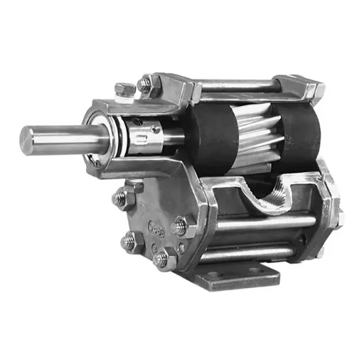
Structurally, gear pumps consist basically of a pair of interlinked gears, usually of the external type, set within a casing that is tightly fitted. As the gears turn, the cavities between the gear teeth trap the fluid and carry it over from the inlet (low-pressure side) to the outlet (high-pressure side). The tight clearances between the gear teeth and the casing prevent backward leakage of the fluid, thereby ensuring that the hydrostatic pressure built up is efficiently transferred to the system. The simple mechanism of the gear pump makes it sturdy, reliable, and easy to maintain.
Gear pumps find common applications in many sectors such as automotive, manufacturing, and agriculture. These pumps have a peculiar application in handling viscosities ranging from oils, lubricants, to polymers. This application’s versatility is further augmented by the pump’s ability to work in high-pressure and high-temperature conditions.
How Do Gear Pumps Operate?
A gear pump carries out transfer with efficient and regular fluid discharge via the gear meshing noise. The basic working concept is two gears, of which one is driving the gear and the other is the bevel gear, enclosed very tightly within a casing. The gears leave a void on the inlet side of the pump via which suction pressure draws fluid into the chamber. The fluid then travels for a brief distance around the outside of the gear’s space between the gear teeth and the casing.
As soon as the fluid is extruded onto the outlet side, the meshing of gears forces it out with constant pressure. This method of displacement provides for a steady flow of fluid, promoting the reliability of gear pumps to transfer both thin and viscous substances. Precise gear alignment, in conjunction with a rigidly constructed housing, reduces leakage internally, thus improving efficiency.
Due to their sturdy design, gear pumps can operate in a high-pressure situation. They lack valves or changing mechanisms internally, so that their chances of failure are limited, making the pumps easy to maintain. The simplicity also makes them applicable for other industrial situations, mainly where the accurate application of fluid is essential. These types of pumps are suitable for handling viscous liquids or materials at higher temperatures.
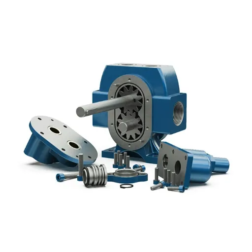
Components of Hydraulic Gear Pumps
Hydraulic gear pumps consist of essential items supporting fluid transfer. Given the following:
- Gears: These are the major components of the pump. Usually, it consists of two meshing gears-one driven (powered) and one idle (driven). It is the gear action that creates the required motion to convey the fluid through the pump.
- Pump Housing: An enclosure for the gears. Under the outside pressure, it must hold firm without any leakage. Usually, the pump housing is made of aluminum, cast iron, or steel so that it can resist the outside pressure.
- Bearings and Shafts: Bearings provide support to the shafts for holding gears, giving stability to the shafts and smooth working. Shafts rotate to give motion to the gears for their correct working.
- Seals and Gaskets: Avoiding fluid leakage and keeping the pump sealed during operation are vital to ensuring the high efficiency and reliability of the pump.
- Pressure Plates or Side Plates: Function to keep gear alignment and reduce internal leakage by providing a tight seal between gears and the pump housing. These are usually made of materials that would resist wear.
Together, these components ensure that the pump operates under high pressures and harsh environments, giving the hydraulic gear pump a wide scope for industrial applications. The simple design reduces wear and tear while offering accuracy and reliability in carrying fluids through different environments.
Types of Gear Pumps
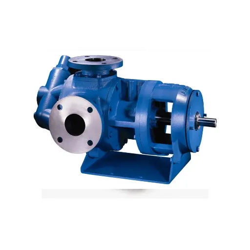
Internal Gear Pumps
Internal gear pumps belong to the positive displacement variety and use two intermeshing gears to impart motion to the fluid for precision and efficiency. The inner rotor that has fewer teeth is placed eccentrically with respect to the outer gear, which lets the flow through the chambers provided between the gears. The crescent-shaped divider placed between the gears serves to separate the suction and discharge sides, assuring sound flow with minimal pulsation.
Internal gear pumps are one of the most versatile types of pumps and, depending on their specifications, can have a working range spanning from lubricating oils to adhesives and high-viscosity fluids. Also, such pumps are ideal for low-shear flow, an important feature for shear-sensitive or delicate fluids. They are in operation in all sectors, including chemical processing, food production, and hydraulics.
The internal gear pump lags in efficiency in raw design processing as the advanced working requires materials and technologies developed to reduce friction and increase durability. For instance, close precision machining and improved sealing solutions allow an internal gear pump to reduce leakage as much as possible and to perform well in very high temperatures and pressure. Being so, internal gear pumps can stand great demands related to industrial and commercial applications.
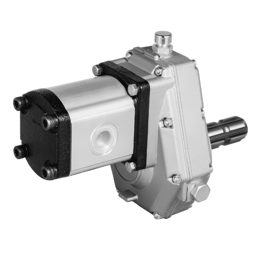
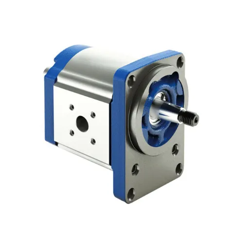
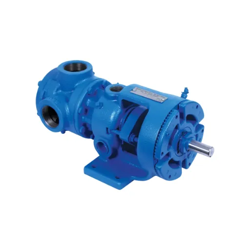
External Gear Pumps
External gear pumps are sturdy and versatile components that find applications across industries in fluid transfer. Two intermeshing gears—one driving the other—work inside the housing. When the gears rotate, fluid gets trapped in the spaces between the teeth and the pump casing, thereby effecting positive displacement and ensuring a constant flow rate.
The modern approach to developing external gear pumps aims to ameliorate performance, reliability, and energy efficiency. The inclusion of materials resistant to wear dehydrated the adverse action of the abrasive particles suspended in liquid, or handled violently aggressive chemicals in all severity, on-plants for very long hours of operation. Moreover, CFD analyses were used during the design process to optimize gear profiles for reducing turbulence and achieving high volumetric efficiency.
External gear pumps are great at delivering fluids under high pressure with utmost precision. This puts the industries of chemical processing, automotive, and oil and gas in the position of valuing precise dosing and dependability. Coupled with their wide viscosity ranges, coupled low upkeep, external gear pumps make for an economical instrumental choice for a plethora of working environments.
Comparing Gear Pumps with Other Common Types of Pumps
The types mostly consider gear-type pumps against centrifugal, diaphragm, peristaltic, vane, lobe, progressing cavity, grinder, mud, surface, and trash-type pumps.
Applications of Gear Pumps
Manufacturing Sector
Gear pumps find widespread application in manufacturing, attributable to the character of fluids they can work with, covering a wide range of viscosity and flow rate, all while maintaining precise and constant gradations in flow rates. We will now consider five applications of gear pumps in manufacturing:
- Lubrication Systems: The gear pump is generally used in lubrication systems for manufacturing machinery. They provide a constant and precise quantity of lubricant to essential components such as bearings, gears, and conveyor systems that reduce friction and wear.
- Chemical Dosing: Many manufacturing processes, especially plastics and chemicals, require chemical dosing with precision. Gear pumps are used for the metering and delivery of chemicals in controlled amounts, ensuring consistency in the product and reducing wastage.
- Hydraulic Power Units: Gear pumps find applications in hydraulic systems that provide power to manufacturing equipment such as presses, lifts, and robotic systems. Being able to work under high-pressure conditions with reliability, they are preferred.
- Adhesive Dispensing: In processes manufacturing goods with the aid of adhesives (packaging or assembly lines), gear pumps dispense adhesive materials in exact quantities and with regularity, thus securing a strong bond without excess application.
- Coolant Circulation: Gear pumps are suitable for circulating cooling liquids for CNC machinery or any heat-sensitive equipment; they help in maintaining temperature levels and extending the life of equipment.
Thus, the above applications stand as a testimony to the fact that the versatility and reliability of these pumps remain the key to greater efficiency and enhanced functionality in industrial manufacturing setups.
Oil and Gas Industry
It is due to the rugged construction of gear pumps that these pumps have been integral to the oil and gas industry. Their precision treatment of viscous and abrasive fluids makes their application part of crucial operations, thereby ensuring smooth working on both upstream and downstream ends. The following are five types of gear pump functions in the oil and gas sector:
- Crude Oil Transfer: Gear pumps transfer crude oil from storage tanks into processing facilities. Allowed under exceedingly high pressure for a viscous liquid, the pump and pipeline combined operate without interruptions, rendering downtime minimal, optimizing production rates.
- Chemical Injection Systems: Gear pumps inject measured quantities of chemicals, including corrosion inhibitors and demulsifiers, into pipelines and processing systems to maintain pipelines correctly and prolong equipment life.
- Lubrication Systems: Gear pumps are vital in rigging, drilling, well construction, refinery operation, and maintenance. They provide consistent lubrication to critical machine parts. Proper lubrication ensures friction is minimized, thus increasing the life of the machine and preventing untimely mechanical failures.
- Hydraulic Power Systems: Gear pumps are used in frac’ing and other high-pressure drilling operations to supply and maintain hydraulic power for the highest operational efficiency.
- Metering and Blending: Gear pumps are the core component for precise metering and blending of fuels, lubricants, and additives. They are very accurate, guaranteeing that the product is consistent and meets stringent industry specifications.
These applications are a testimony to the reliability and flexibility offered by gear pumps in the highly complex and demanding operations in the oil and gas industry, bringing deliverable enhancements to performance and safety.
Agriculture and Chemical Processing
Gear pumps work in the agriculture and chemical industries, providing precision and efficiency for a number of fluid-handling tasks in the industry. The rugged construction and adaptability to work with liquids of varying viscosity make them necessary for handling complex materials. Here is a detailed list of five important applications in these industries:
- Fertilizer Dispensing: Gear pumps dispense liquid fertilizer in measured and controlled amounts to support precision agriculture practices with the ultimate goal of improving crop yield. It is the presence of uniform flow rates that reduces waste of fertilizer and enables proper application.
- Chemical Transfer: Used for handling reactive or corrosive chemicals, gear pumps are normally made of specialized materials such as stainless steel and Teflon coating to ensure durability and resistance to chemical damage, making these operations safer and more reliable.
- Pesticide Spraying: Gear pumps offer precise control over pesticide flows, which is critical for effective pest management. Their ability to handle low-viscosity fluids ensures the even application of pesticides, ultimately benefiting sustainable agriculture.
- Feed Additive Metering: Commonly seen in livestock farming, these pumps ensure precise metering of liquid feed additives for nutritional supplementation of animals. Precise metering will improve feed utilization and produce healthier livestock.
- Polymer Mixing and Transfer: In chemical processing, polymer mixing and transferring is a differentiating process done by gear pumps for materials of varying viscosities. Quantitative pumps ensure that each batch meets the required technical specifications to ensure the production of plastics and resins.
These applications speak of the versatility and reliability of gear pumps in agriculture and chemical processing, where precision, safety, and efficiency are very important. These pumps use advanced technologies to fulfill the stringent requirements of industrial processes today.
Maintenance Tips for Gear Pumps
Routine Maintenance Practices
Checkup and repair services are necessary to ensure proper functioning and long-term durability of the gear pumps. The routine maintenance must include the following practices:
- Lubrication Checks: Check periodically to see if the lubricant is adequate, refilling the system when necessary to prevent the wear of moving parts. Follow the manufacturer’s instructions and use the recommended lubricant to maximize performance and reduce friction within the pump housing.
- Inspection of Seals and Gaskets: Inspect the seals and gaskets for any signs of deterioration or damage. Seals that are worn or deteriorated could cause leakage, thus reducing their suction capability, whereby damage to other parts might occur.
- Wear & Tear Watch: Periodic observations of gear teeth, worn shafts, and bushings are needed to catch early-wear conditions. Misalignment and excessive wear will ruin volumetric accuracy and performance.
- Good cleanliness Management: Keep the pump and associated system free from debris, for contaminants could cause blockages and scoring in the pump interior. Use filtration systems as and when necessary to minimize contamination hazards.
- Performance Checks: Measure flow rates and pressures during factory diagnostics and compare results with those at standard properties from which deviations can be identified for corrective actions.
- Thermal Monitoring: High temperature could indicate inadequate lubrication or other mechanical friction phenomena. Measure the working temperature regularly with the use of infrared thermometers and sensors with integrated worried-well-for temperature data.
- Routine Replacement of Parts: Replace wear parts such as bearings and seals following the pump manufacturer’s recommendations to avoid interruptions in operation and keep the pump working efficiently.
By following the above maintenance issues, operators will intend to eliminate mechanical failure due to improper maintenance, minimize downtime, and increase the full working life of gear pumps in severely problematic industrial situations. It is highly recommended that these maintenance processes be incorporated into a comprehensive maintenance schedule, with proper documentation to verify the effectiveness of the maintenance program and for analysis purposes.
Common Issues and Troubleshooting
When dealing with general issues about gear pumps, it is vital to understand the symptoms, followed by the causes of the malfunction. Below are some of the frequently encountered problems, with their probable causes, and with suggested methods for troubleshooting:
If these common problems are treated systematically by operators, the performance of gear pumps is fully optimized. All the troubleshooting moves and observations should be documented to serve as a reference for diagnosing recurring problems and improving long-term operational reliability.
Extending the Lifespan of Your Gear Pump
With longevity in mind, your gear pump needs proper maintenance. Most importantly, it should be properly lubricated with oils just like the industry standards or manufacturer-approved oils, using which friction is minimized to reduce wear and tear of other parts such as bearings and gears. Also, if the pump were improperly aligned with its drive mechanism, the internal parts would suffer unnecessarily from undue stress and could prematurely deteriorate with time.
It is also good practice to maintain acceptable operating conditions. Anything that sets prices beyond highs, temperatures beyond highs, or flow rates beyond those limits considered normal by the pump would be off balance with fatigue, causing it to fail. Installing sensors to keep the conditions variable offers operators data on which they can act immediately to maintain the machine.
Furthermore, it is imperative to check the performance of filtration systems to prevent particulate contamination. Research has shown that particulate matter is one of the foremost causes of pump failure because fine debris erodes the surfaces and may clog internal passageways. Therefore, one should always use filters rated for capturing the finest particles, propped up by a maintenance schedule that ensures timely filter replacements.
Lastly, educating the staff about using and handling gear pumps correctly is crucial. Incidents of human error, such as running a dry pump or exceeding recommended speeds, can be avoided by following instructions and operating procedures. Using advanced monitoring technologies, a rigid maintenance schedule, and an informed workforce provides a sustainable way toward an extended gear pump lifespan.
Selecting the Right Gear Pump
Factors to Consider: Flow Rate and Pressure
When I am selecting a gear pump, I always think of flow and pressure as the outstanding criteria that contribute to the best working efficiency. The flow rate, for instance, in gallons per minute (GPM) or liters per minute (LPM), tells us how fast the pump remains in operation within the system. I have learned that this capacity depends on how much volume of liquid is to be transferred or circulated; any divergence from this can either make the system work insufficiently or strain the pump too much. So I assess the system requirements and check the manufacturer specifications in which the rated flow of the pump is clear.
Pressure is expressed in PSI or bar, signifying basically the resistance the pump must overcome to move the fluid through the system. I focus on both the maximum and operating pressure ratings of the gear pump for compatibility with the particular application. Situations of high system pressure demand a sturdy design, and any pressure beyond the limits might bring about mechanical failures or degradation of the sealing. To reduce risks, I always see to it that these ratings and the safety margins correspond with the needs of the application.
Ultimately, these dynamics are strongly considered in my selection procedure. I see these two as being dependent variables; if one changes, the other accommodates. Considering the operating conditions of the system and armed with an exhaustive set of technical data, I can define the correct gear pump that will offer the best performance, implying the least downtime, and thus the highest reliability, for a given set of applications.
Fluid Compatibility and Application Needs
In the selection of any gear pump system, fluid compatibility stands as the primary consideration affecting operational performance and life. Variations include viscosity, chemical makeup, range of temperature, and corrosiveness, all factors considered in assessing the interaction between pump materials and design with those properties. To provide some counterpoint, a mixture of abrasive or highly viscous fluids necessitates reinforced components possessing wear resistance capabilities, while corrosive chemicals require materials that are either chemically inert or corrosion resistant, such as stainless steel or certain polymers.
A search using advanced research and analysis tools for the technical specifications of gear pumps according to application requirements would yield specific decisions. Engineers, therefore, while considering sets of data such as flow curves, pressure limits, and corrosion charts, will eventually run into situations where design choices must be implemented that guarantee high efficiency and long maintenance intervals. Application data, such as temperature extremes or clean-in-place (CIP) requirements, sets the boundaries for designs to meet industrial, chemical, or pharmaceutical standards.
Frequently Asked Questions (FAQ)
Q: What is a gear pump?
A: A gear pump is a positive displacement pump using two rotating intermeshing gears to move fluids. Fluid enters the pump through the inlet side and leaves through the outlet side, effectively transferring the fluid from the suction side to the discharge side of the pump.
Q: How do the gear pumps operate differently from centrifugal pumps?
A: Being a positive displacement pump, a gear pump moves a fixed amount of fluid during each rotation; hence, they are better for fluids that need to be delivered at higher pressures and in precise quantities. In contrast, centrifugal ones work to propel fluids by means of rotational energy.
Q: What components make up a gear pump?
A: A gear pump consists of gears, casing, idler, and seals as its major components. They could be spur, herringbone, or helical gears and are mounted on separate shafts. The design ensures a zero leak and slip from the inlet to the outlet.
Q: How does a gear pump work?
A: One of the gears is driven by a motor and, in turn, drives the other gear. As the gears rotate, the fluid is drawn into the pump at the suction side through a vacuum. The fluid is trapped between the gears and the pump casing on its way out of the discharge side.
Q: What are the advantages of pressing gears?
A: These pumps are capable of operating at higher pressures, with a very precise flow rate, and can handle thicker/temp fluids. It is commonly used in fluid power applications. They are very durable and highly reliable.
Q: Are gear pumps able to pump different types of fluids?
A: Yes, gear pumps are capable of pumping all kinds of fluids, such as fuel oil and other heavy materials. The design of these pumps allows them to be effective for liquids of different viscosities; hence, they are versatile in industrial applications.
Q: What maintenance is required for gear pumps?
A: Common maintenance for gear pumps includes wear checks on the gears, making sure that lubrication has been properly applied, and inspecting for any seal leakage. It is crucial to monitor the tolerance between the gears and the casing to maintain satisfactory performance and avoid mechanical failure.
Q: What is the effect of thermal expansion on gear pumps?
A: Thermal expansion poses a threat to the working of a gear pump under high-temperature conditions. Such changes in viscosity offered by the fluid and the dimensions of fitting between the gears and the casing are considered to be efficiency-impairing factors and deflect the amount of fluid actually pumped.
Q: Are there types of gear pumps?
A: Internal and external gear pumps, to name a few, are in existence. Internal gear pumps constitute one gear inside another, while external gear pumps have two identical gears in mesh against each other. They are used in varying fluid power applications and offer different advantages depending on what the application in question requires.
Ready to Find the Perfect Gear Pump?
By using quantitative information and industry specifications for searching, the approach circumvents the usual drawbacks of a generic search result so that trusted data-based results could be provided for each individual working environment.