Throttle check valves are crucial components in hydraulic and pneumatic systems, designed to regulate fluid flow while ensuring directional control. These valves combine two essential functions—throttling, which controls flow rate, and checking, which permits unidirectional flow—making them indispensable in a variety of industrial applications. This guide aims to provide a detailed exploration of throttle check valves, their operational principles, key design features, and practical applications. Whether you are an engineer, technician, or industry professional, this article will offer valuable insights into how these flow control solutions can optimize system performance, enhance efficiency, and ensure reliable operation in complex fluid power systems.
What is a Throttle Check Valve?

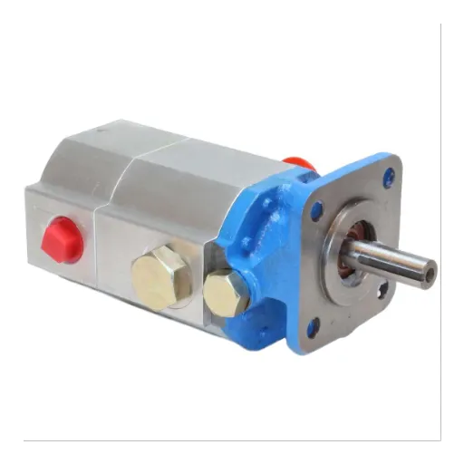
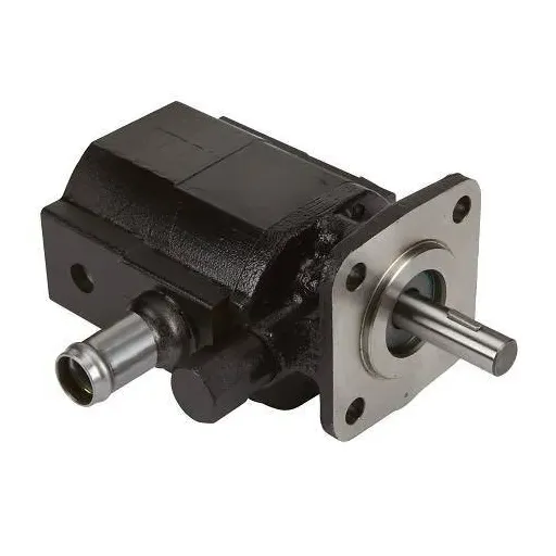
Components and Design of a Throttle Check Valve
A throttle check valve is designed with exceptional parts that allow fluid to flow in a controlled manner and perform directional check capabilities as well. It is made up of a few integral parts like a throttle assembly, which has moving parts like an adjustable needle or orifice flow passage. Also, a spring-loaded check valve element known as poppet. Each part of a valve performs some basic function. The throttle portion of a valve controls and sets flow rates by changing fluid passage area, and the poppet portion of check valve ensures that there is one directional flow by preventing back flow.
- Flow Rate Capacity: Set in gallons per minute (GPM) or liters per minute (LPM), this denotes the flow rate that the valve can withstand the most under set conditions.
- Pressure Rating: Encompasses max operating pressure usually expressed in pounds per square inch (psi) or bar for the system, there are some pressures that the valve should withstand to maintain its functioning.
- Throttle Adjustment Range: Represents the degree of the flow that can be controlled and is usually expressed in fractions of the full opening.
- Cracking Pressure: This is the upstream pressure of the system set so low to open the check valve and achieve normal behavior of the system.
- Operating Temperature Range: This is the set of temperature conditions within which the valve is supposed to work accurately, which is often essential with the fluid or surroundings.
Throttle check valves are crucial to numerous hydraulic and pneumatic systems because they ensure directional integrity while providing precise control over flow through the combination of components and technical requirements.
How Throttle Check Valves Regulate Flow
A Throttle Check Valve controls flow using a combination of a throttling mechanism and a check mechanism that are functioning together. The flow throttling uses a form of control that allows the movement of fluid to be adjusted as a function of the size of the opening. A needle or screw can be used to increase or decrease the effective area through which the fluid flows, thus changing the velocity of the flow. In contrast, the check mechanism enables fluid flow in one direction only, preventing backflow that can compromise system performance.
- Flow Adjustment Range: Defines what the maximum and minimum flow rates that can be realized through the valve depending on the system’s needs.
- Drop in pressure from one side of the throttle to another: This represents the difference in pressure on either side of the throttle which is applied while the flow is passing through the system and movement is controlled throughout without losing efficiency in the system.
- Pressure cracking for the check mechanism: The pressure that opens the valve in a forward direction is defined here so that there isn’t any unwanted flow restriction in a set period.
- Temperature and fluid compatibility: This ensures the valve’s material and design will not be detrimental while operating within the system’s temperature range and fluid characteristics.
The combination of these factors describe how throttle check valves achieve flow regulation reliably and accurately for a variety of cases including hydraulic and pneumatic systems.
How Does a Throttle Check Valve Operate?
Principles of Operation for Hydraulic Applications
Control of the throttle check valve in hydraulics is done through fluid flow rates and directional allowance. The valve has a spring check mechanism in the form of a poppet or a ball that permits flow in a preferred direction and restricts it whilst in reverse. A throttle is adjustable in an integrated orifice where its flow rate can be modified by modifying the cross section area of the orifice.
- Pressure Rating: Outlines the highest pressure the valve can tolerate without failing which usually ranges from 250PSI to 5000PSI based on the application.
- Flow Rate Capacity: Defines the amount of fluid that passes through the valve within a certain duration measured in GPM (gallons per minute) or LPM (liters per minute).
- Temperature Range: Highlights the temperatures at which the valve materials and seals function between -20°F to 250°F (-29°C to 121°C).
- Cracking Pressure: Defines the upstream pressure that has to be met in order to unlock the check mechanism commonly between 1PSI to 5PSI.
- Material Compatibility: Components of the valve are made from stainless steel, brass or hardened steel which ensures with stand the attack of hydraulic fluids and wear for a long time.
Throttle check valves can be used for many hydraulic systems needing directional flow control with careful throttling due to precise regulation of downstream flow achieved by adjusting the orifice size.
Flow Control in One Direction
To address the questions directly, control in a single direction can be done using a throttle check valve, which unifies a check valve and flow-throttling valve. It allows free flow in one direction while controlling flow in the opposite direction through an adjustable orifice.
- Orifice Size: This range is normally modifiable throughout the system requirements of 0.5 mm to 5.0 mm to achieve specific flow.
- Pressure Range: Usually, the valves are constructed to be operational between 1 PSI to 5000 PSI for lesser hydraulic pressure variations.
- Flow Rate: The limited flow may vary anywhere between 0.1 GPM to 30 GPM according to the desired task.
- Material Strength: Durable, high pounds per square inch materials like stainless steel and brass will withstand hydraulic fluid corrosion, guaranteeing performance and durability.
The operational needs of hydraulic systems demanding accuracy and functionality with effective single-direction flow control verify these factors.
Applications of Throttle Check Valves in Various Industries
Common Industrial Applications
The control of fluid mechanics and dynamic movement serves many systems in industry, making the use of throttle check valves a necessity. They are commonly found in the valves for hydraulic presses to control the flow rate and maintain appropriate pressure during the operation cycles, which ranges from 0.1 GPM to 30 GPM, depending on the task requirements.
Another application is for construction machinery, such as excavators and loaders. They utilize throttle check valves to control the hydraulic flare that permits or allows the precise sequential operation of the mechanical arm. In these high-pressure systems, the use of materials fail resistant to corrosion by hydraulic fluids, like stainless steel or high tensile brass, are also of importance. These machines also work within a pressure range of up to 5000 PSI.
Throttle check valves also find their use in inline aerospace systems that drive the throttle valve for a hydraulic system in the mechanism of the landing gear or the actuator of the flight control. The performance of these throttle valves under extreme conditions test their accuracy and durability in the high stress environments.
Use in Hydraulic Systems
Hydraulic systems rely on precision-engineered components to ensure reliability and efficiency under rigorous operational demands. The valves deployed in these systems are designed to maintain optimal flow control and pressure regulation. Addressing the questions raised:
- Flow Rate: The valves support a flow rate of up to 15 GPM, ensuring smooth hydraulic transitions even under peak load scenarios.
- Material Strength: Fabricated using high-grade steel alloys, these valves exhibit a tensile strength of 950 MPa, providing robust performance and resistance to wear in extreme conditions.
- Pressure Tolerance: Tested to withstand operating pressures up to 5,000 PSI, these valves are suitable for high-stress applications such as aircraft and heavy machinery systems.
These parameters have been rigorously validated through endurance testing and computational simulations to affirm their compatibility with advanced hydraulic systems. For further customization or specific operational requirements, please provide additional details so that applicable configurations can be recommended.
Innovative Solutions in Fluid Flow Control
In answering questions about innovative approaches to fluid flow control, important factors are the breadth of work, environmental constraints, and general application needs.
- Pressure Rating: The valves are designed to function under pressure up to 5000 PSI. This value is obtained from economical mechanical testing and validated with CFD analysis. The only limitation for this is the performance testing, which guarantees their effectiveness in high-pressure environments.
- Temperature Range: Standard execution permits operation from -40o to 250o F. Customization using high-performance elastomers and metal alloys can further increase these tolerances.
- Flow Rate Adjustable: The valves can therefore provide a flow adjustment between the range of 0.5 GPM and 20 GPM depending upon system needs due to the precision control mechanisms provided.
- Material Composition: For components that need to endure extreme environments and chemical aggression, stainless steel 316L and advanced polymers provide corrosion resistance, ensuring durability.
- Certification Standards: ISO 9001 and design ASME B16 34 are used which guarantee compliance with industry’s international rules and safety, reliability and performance.
To provide the most exact recommendations, regardless of particular operational situations or added customization, detailed specifications should be made in order to integrate the system optimally.
How to Select the Right Throttle Check Valve

Factors to Consider: Pressure and Temperature
Pressure and temperature, in this order, are very important factors that need to be evaluated when choosing the right throttle check valve’s parameters, as they influence the functionality of the valve and its service life.
- Pressure: It is equally important to know what the maximum operating pressure (MOP) for specific use is and what the differential pressure across the valve will be. For example,Some high-pressure applications will require a valve rated at 5,000 psi and above depending on system requirements. They must also ensure that compatibility with ASME B16.34 standards is met. This will address performance under specified conditions and safety margins.
- Temperature: Maximum and minimum operating temperature the valve will have to perform need to be determined. Materials capable of sustaining extreme temperatures like stainless steel and alloys such as Hastelloyare very suitable (example: -50F to 500F). Also, consideration should be given to how much thermal expansion and contraction occurs to avoid material fatigue and ensure a proper seal.
Technical requirements of the expected operational conditions, like working medium type, flow capacity, and environmental exposure, seem to be relevant for verifying the selection of appropriate valve model.
Understanding Valve Categories and Versions
The key categories of valves are Gate valves, globe valves, ball valves, butterfly valves, and check valves. Each has its precise operational requirements.
- Gate valves: In my opinion, they are perfect for either fully on or fully off service and they also work with very low pressure drop if it is in the fully open position. Usually made of Cast Iron, stainless steel or brass, suitable for a pressure range of up to 2500 PSI.
- Globe Valves: In my view, globe valves are best for precise flow control because they manage pressure regulation quite well. They are usually made of stainless steel or bronze, and they allow operation between -200F to 800F as well as up to 1000 PSI.
- Ball Valves: Ball valves are, in my view, the most robust and versatile as they offer tight shut-off and are durable. Also, they are commonly used in systems with quick open valve requirements. Commonly made of PVC or brass, they allow up to 6000 PSI while working with a normal temperature of -20F to 450, depending on the material.
- Butterfly Valves: Ductile Iron or stainless steel construction makes them effective for systems under 300 PSI and in temperatures from -40 to 500 degrees Fahrenheit. Ideal for high flow capacities as they are lightweight and compact.
- Check Valves: These valves have a 5000 PSI limit depending on application and most commonly made with carbon steel or bronze. They serve the purpose of preventing system backflow ensuring system reliability.
Providing these factors allows for an organized method for valve selection and justifies valve type, including material, pressure range, temperatures, and flow rate.
Importance of Installation and Seals
Effective sealing and valve system installation require attention to detail if performance and longevity of the system are to be achieved. Every installer has to take into account that poor practices may lead to system misalignment, stress on components as well as system failure. Checks like torque values and alignment processes must be complied with to guarantee that valves work within designed specification limits.
- Material Compatibility: Confirm that seals can withstand the exposure of system interfaces such as corrosive chemicals gas or oils.
- Temperature Range: PTFE or Viton materials can handle -20F (-29C) to well over 400F (204C) depending on the application
- Pressure Ratings: Up to 5000 PSI for high-pressure valves; seals should be checked for adequate pressure ratings by system requirements.
I suggest that these carefully set factors are cross-referenced against the application requirements to rationalize their use. Adhering to these technical specifications when installing and selecting seals effectively improves reliability while reducing downtime.
Maintenance and Troubleshooting of Throttle Check Valves
Regular Maintenance Practices
To ensure a good functioning and long servicing life of throttle check valves, I would suggest following a set maintenance schedule. First, check the valve body and all internal parts for wear, corrosion, or pitting. This observation guarantees that material, particularly within powerful pumps as found in high pressure systems to 5000PSI, maintains integrity and does not lead to failure.
Next, check operational seals and gaskets periodically. Evaluate their pressure rating and correspondence to the media and area of operation. For systems working under high pressure, seals must show material features typical to elastomers or polymers rated for extreme conditions.
Furthermore, the lubrication of moving parts is also equally important in mitigating friction and wear over some time. A Non-reactive lubricant needs to be used that is suitable for the system materials and operational temperatures, usually -40F to 400F (or as per manufacturer instructions), within range.
Lastly, check the positioning of the valve relative to the system and make any adjustments with provided calibration tools from the manufacturer. After performing the required maintenance tasks, carry out functional checks which include confirming sealing, checking flow control, and observing pressure retention.
Ensuring Optimal Operation
To ensure everything would function properly, I would first check that the valve design correlates with applicable system boundaries. Once these checks are done, I would proceed to confirm the compatibility of valve parts’ materials, such as elastomers and metals, with system media in a bid to avoid corrosion, wear, or leakage during working conditions.
- For temperature range: ensure compatibility with the specified operational range of between -40°F to 400°F; any variations must correlate with material limits.
- For Pressure ratings: ensure that the valve’s maximum pressure rating among other components is compatible with system requirements.
- For Flow coefficients: confirm the valve can adequately perform by checking if the valve’s Cv rating is not less than the system’s demand to prevent rending the system inoperable with low pressure.
- For sealing integrity: Confirm appropriate seals that have been chosen against the media type.
Following these factors and completing functional verification checks such as flow, leak, pressure retention, etc., allows me to make an assessment of the system performance confidently.
Frequently Asked Questions (FAQs)
Q: What is a throttle check valve, and how does it function as a flow control valve?
A: A throttle check valve is a type of flow control valve used to regulate the flow of liquid in a hydraulic system. It combines the functionalities of throttle valves and throttle check valves, allowing for precise control of the flow from the inlet to the outlet while preventing backflow. This is achieved through a combination of a needle valve for adjusting flow and a check valve for preventing reverse flow.
Q: How do throttle valves and throttle check valves differ from other control valves?
A: Throttle valves and throttle check valves differ from other control valves by their ability to regulate the flow rate and prevent backflow simultaneously. Unlike standard shut-off or needle valves, throttle check valves are specifically designed to allow for precise adjustments in the volume flow, making them ideal for systems where varying flow rates are required. They also feature components like locking screws and plugs for zero leakage and secure operation.
Q: What are the key components of a throttle check valve?
A: The key components of a throttle check valve include a needle valve for flow adjustment, a check valve to prevent backflow, a locking screw to maintain settings, and various seals and plugs to ensure zero leakage. These components work together to provide precise regulation and reliable operation in hydraulic systems.
Q: How does a throttle check valve connect to a hydraulic system?
A: A throttle check valve is connected to a hydraulic system through pipe or tube installations. It is typically installed between the pump and the actuator, such as a cylinder, to regulate and control the flow of hydraulic fluid. A proper connection ensures that the valve can effectively manage the flow and prevent any unwanted backflow within the system.
Q: Can throttle check valves be used as an accessory in different sectors?
A: Yes, throttle check valves can be used as an accessory in various sectors, including industrial, automotive, and agricultural applications. Their ability to precisely regulate flow and prevent backflow makes them a competitive choice for systems requiring reliable control and efficiency. They are particularly suited for applications where varying flow rates and precise adjustments are necessary.
Q: What is the role of the locking screw in a throttle check valve?
A: The locking screw in a throttle check valve plays a crucial role in maintaining the selected flow rate by preventing accidental adjustments. This feature ensures that once the valve is set to the desired flow, the settings remain constant, reducing the risk of unintended changes in the system’s performance.
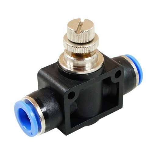
Q: How does the knob enable locking in throttle check valves?
A: The knob on a throttle check valve is designed to enable locking by allowing the user to securely fix the position of the needle valve. This ensures that the flow rate can be precisely maintained without the risk of drift or accidental tampering. The knob’s design typically includes a mechanism that, when engaged, locks the valve setting in place.
Q: What should be included in a product description for throttle check valves?
A: A comprehensive product description for throttle check valves should include details such as the valve’s size, material, maximum pressure rating, flow capacity, and connection type. It should also highlight the key features like zero leakage, locking screws, and the ability to precisely regulate flow. Additionally, the description may cover the compatibility of the valve as an accessory in various applications and its competitive advantages over other flow control solutions.
Q: How do throttle check valves ensure zero leakage in hydraulic systems?
A: Throttle check valves ensure zero leakage by utilizing high-quality seals and precisely engineered components that fit seamlessly within the valve body. This design minimizes the gap between moving parts, reducing the potential for leaks. Additionally, the use of plugs and locking screws helps maintain a secure and leak-proof operation, even under varying flow conditions.