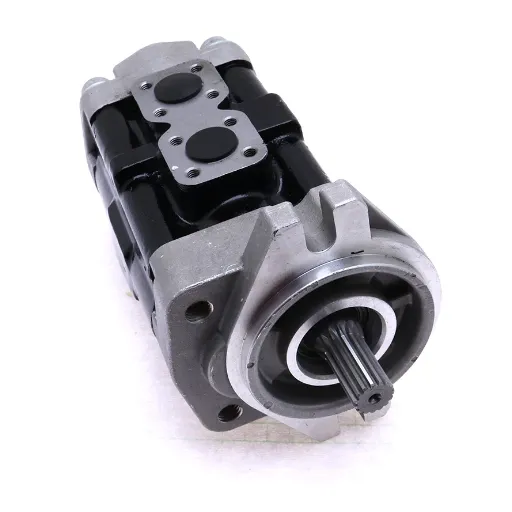
Hydraulic pumps constitute essential parts of a variety of machinery and industrial systems, and optimal performance of these pumps ensures efficiency and safety of operations. Testing is a vital process in defining the condition, performance, and overall reliability of a hydraulic pump, whether it is being used in diagnosing a system problem or for preventive maintenance. The following manual guides you in conducting a proper hydraulic pump test and provides detailed instructions and salient considerations. Following these guidelines will equip you with the skills to evaluate pump performance, identify possible problems, and decide on repair or replacement.
Importance of Regular Testing in Hydraulic Systems
Maintaining Efficiency and Reliability
Testing hydraulic systems regularly is a practice needed to ensure the smooth performance of the system and to prevent accidents and system failures. A hydraulic pump can gradually lose its functionality due to simple causes: aging and wear, contamination, poor treatment, etc. Regular inspections help operators spot any inefficiencies like changes in flow rate or abnormal pressure variations that, if not controlled, could jeopardize the reliability and productivity of an entire system.
Maintenance leads to improved functionality in the system and a reduction of losses resulting from friction, leaks, or improper fluid interactions. Testing the operation of the pump so that it can detect signs of cavitation and air entrainment will protect major damage to system components. At the same time, keeping the operating temperature and fluid viscosity right for the application will minimize unnecessary stress to the pump, thereby further extending its operational life.
By embracing a proactive testing schedule, operators can curb unplanned downtime and reduce repair costs. Early warnings of potential problems, say, worn seals or damaged components, allow replacements to be made in time, preventing much larger system failures. A working system also means all parts are safe because they comply with the manufacturer’s specifications. Keeping detailed records of test results and maintenance activities backs the long-term reliability of a system.
Ensuring Safety in Hydraulic Systems
Safety in hydraulic systems comes from properly designing the system, regularly maintaining it, and following rules when operating it. Components should be periodically inspected for any signs of wear or damage and replaced according to the manufacturer’s guidelines, so they do not fail. Various parts must be assembled using compatible components and good-quality hydraulic fluids so that no contamination occurs. Exposure, in turn, leads to bad performance, more breakage, and thus more breakdowns. Reliable sources like ISO standards for hydraulic systems establish important parameters that safeguard safety and efficiency.
There is no room for compromise when it comes to operational training for hydraulic systems. Operators must be fully aware of the proper use of equipment; maintenance personnel must be aware of emergency procedures in case of potential hazards. A hydraulic system will catastrophically fail if it is overloaded or pressed beyond its pressure limits. Hence, systems should be operated within the limits for which they were designed. The regular testing and maintenance of shut-off systems and pressure relief valves would ensure their proper function in times of need.
At last, recording maintenance activities and the performance metrics is what makes proactive safety management. Records allow technicians to identify recurring events and situations. They are then able to make appropriate changes to prevent future problems. Well-documented histories ensure that inspections can be appropriate with the wear patterns of the system and with operational demands, which also supports reliability and safety for as long as possible. Following these recommendations ensures efficient operation and reduces accident potential for the hydraulic system.
Consequences of Neglecting Testing
Regular testing being ignored in hydraulic systems may pose operational and safety implications. Among the many risks, system failure is one of the critical risk factors that result from undetected component wear and damage, particularly hoses, seals, or valves. Without periodic testing, such problems will persist without recovery, suddenly breaking down and compromising the system’s performance, not to mention the large amount of downtime.
Neglecting testing also increases the likelihood of accidents. These hydraulic systems operate under great pressure, and undetected faults may see hoses bursting, fluid leaking, or equipment suddenly malfunctioning. Such occurrences can injure personnel and compromise the equipment and infrastructure around them. Regular testing goes a long way in spotting hazards that may grow and, thus, protect human and machine assets.
Finally, disregarding certain testing protocols affects the long-term reliability and efficiency of hydraulic systems. Several minute deficiencies, such as fluid contamination or minor leaking, after some time impair system performance greatly. When left unchecked, certain issues may blow out into huge repair or replacement jobs. Constant testing acts against this risk in maintaining the good operational integrity of the system and extends its working life by choosing safety together with cost-efficiency.
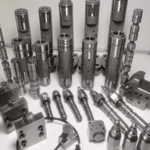
Tools and Equipment Required for Testing Hydraulic Pumps
Essential Tools for Hydraulic Pump Testing
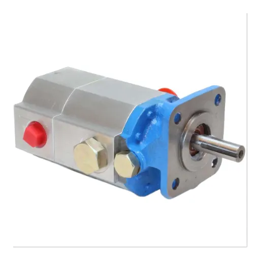
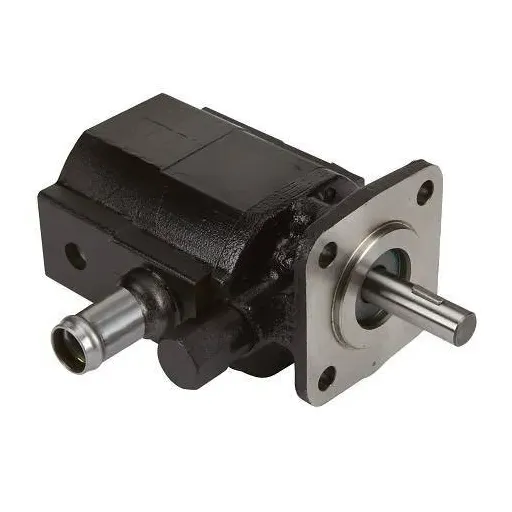
Preparing for the testing of hydraulic pumps requires a wide array of specialized tools to carry out proper diagnostics and perform optimally during evaluation. The following detailed list describes the essential tools necessary for this purpose and the functions they perform:
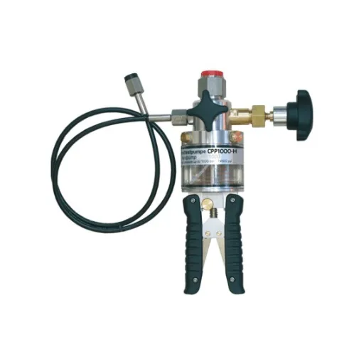
🔧 Pressure Gauges
Pressure gauges measure the system pressure at any given point in the hydraulic circuit and must be accurate. The gauge must have the appropriate range, such as the maximum working pressure of the system being measured plus an additional 25-50% in order to give reliable readings and ensure safety.
📊 Flow Meters
The flow meter measures the composite volumetric flow-rate delivered by the pump according to the power-load conditions. The modern digital flow meter might incorporate a data logger, which is of immense help in real-time monitoring and recording for further analysis.
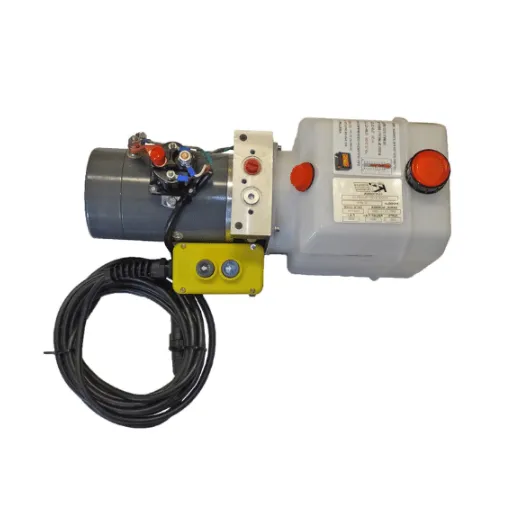
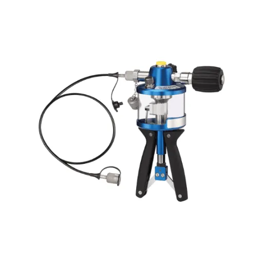
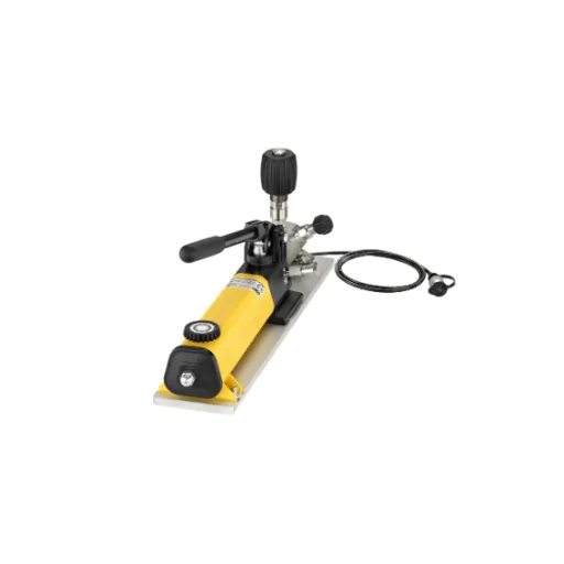
🏗️ Hydraulic Test Bench
A hydraulic test bench allows controlled testing of pumps under different load and pressure conditions. These test benches are usually customizable with feedback systems to provide accurate readings.
🌡️ Thermal Imaging Cameras
Thermal imagers detect abnormal heat signatures in hydraulic systems, which may be a sign of internal leakage, pump inefficiencies, or overheating components.
🌡️ Infrared Thermometers
These provide surface temperature readings of key components. Fluctuations in temperature can be quickly established and associated with friction or excessive wear in the pump or system.
🔧 Filter Carts
Contamination is probably the number one cause of hydraulic pump failures. Filter carts are used for oil cleanliness analysis, sampling, and system flushing alongside high-efficiency filtration units during testing operations.
⚡ Digital Tachometers
These instruments determine the rotational velocity of the pump shaft, which correlates the speed of the pump with flow rates and pressure, giving a measure of efficiency.
🔌 Multimeters and Circuit Testers
Electro-hydraulic pumps use an electrical continuity tester and a multimeter to diagnose pump control systems and check sensors and actuators.
Each test tests for a certain aspect of the pump’s condition, so the testing is comprehensive and authoritative. Using these instruments simultaneously allows for comprehensive diagnostics, which maintain the results, allowing the maintenance team to accurately detect faults. Choosing the right tools is critical, affecting the results since the tools must be highly accurate and must be compatible with the hydraulic system.
Selecting the Right Pressure Gauge
Choosing a pressure gauge can be an important task while analyzing and maintaining hydraulic systems. An ideally chosen gauge ensures correct pressure readings that help determine the system’s performance and any abnormalities. Some factors to consider when selecting a pressure gauge include pressure range, the nature of the fluid, and the general environment in which it is installed. Stainless steel construction gauges, for example, are suitable for corrosive environments or those with extreme temperatures, whereas ordinary brass gauges are good enough under less stringent conditions.
The accuracy class of the gauge holds paramount value as well and ought to be relative to the precision level required for the system. Whilst high-precision applications demand a gauge of at least 0.25% in terms of accuracy class, typical industrial fields easily operate with accuracy classes of 1% or 2%. Watch out for the size of the gauge dial too; large dials of 4 in. or more are appropriate in environments where the reading will be taken from a distance.
Toward the end, state-of-the-art digital pressure gauges with data-logging capabilities offer higher functionality so operators may monitor trends and store data for predictive maintenance. If the gauge is certified for meeting industry standards such as ASME B40.100, then assurance is provided that the gauge will measure reliably and accurately for optimum operation of the system.
Additional Equipment for Comprehensive Testing
For exact and consistent testing results, the incorporation of extra equipment is necessary. Take digital manometers, for example-they can measure pressure more precisely than the usual analog-type meters. Such instruments find most uses where high accuracy is concerned because some of their features include data storage and advanced calibration techniques.
Next come the flow meters that allow the operator to measure the rate at which a fluid or gas travels within the system. Ultrasonic or thermal mass flow meters are perfect for dynamic systems since they operate non-intrusively and provide more advanced analytics.
Temperature sensors like RTDs and thermocouples are used for the control and verification of thermal conditions. Correlating pressure and flow measurements garners an exhaustive idea of the system operating under different operational conditions.
Finally, bringing in data acquisition systems enables multi-synchronized monitoring for trend analysis as well as real-time diagnostics. Configured for this, the systems practically aid predictive maintenance by identifying anomalies before equipment failures. Thus, equipping these high-end tools with certified gauges offers a sturdy and trustworthy approach to system testing and system monitoring.
Step-by-Step Process to Test a Hydraulic Pump
Preparation Before Testing
The test outcome is valid only if preparation is systematic before performing the actual testing of the hydraulic pump. First, carefully inspect each element for evident wear or damage; contamination possibilities must also be checked. Ensure utmost cleanliness of the hydraulic fluid, whether of the grade specified by the manufacturer or if it meets temperature requirements. Next, ensure that every connection in the hydraulic system is tight and sealed against leaks because even the smallest imperfections could have an impact on the reading or system performance.
Ensure the proper calibration of the testing instruments, such as pressure transducers, flow meters, and data acquisition systems, against certified standards. Checks should be carried out frequently, following the manufacturer’s recommendations, to maintain measurement precision. Furthermore, keep in mind to make sure that the test environment remains free from bumps or vibrations, temperature fluctuations, or even electromagnetic disturbances, for such factors can serve as noise sources in your data.
Lastly, examine the technical documentation of the hydraulic pump, together with its operation, specifying, for example, the nominal flow and pressure limits. This makes sure that the test is done within the limits of operation specified for the pump, avoiding, if possible, damage to equipment.
Conducting the Test: Step-by-Step Instructions
- Setup and Initialization: A hydraulic pump setup begins with securely mounting it to the test bench while securing all fittings and connections thoroughly so as to prevent any leakage. From here, the hydraulic fluid reservoir is connected to the system, keeping the fluid within the level recommended by the manufacturer. All diagnostic testing equipment is powered on, and the sensors such as pressure transducers and flow meters should be calibrated according to the specs. This step ensures baseline accuracy for data collection.
- Baseline Measurement: Conduct energization of the hydraulic system while allowing the pump to run at its nominal flow rate and target pressure. The system temperature ought to attain steady state since any temperature fluctuation would adversely affect the fluid viscosity and system performance. Record the baseline readings of flow, pressure, and temperature, ensuring that these values remain well back within the operational range specified for the pump in the manufacturer’s literature.
- Dynamic Performance Testing: Apply gradually varying load to the pump by adjusting system resistances to mimic actual operating conditions. Measure the response of the pump at different flow rates and pressure points, taking data at incremental steps. Focus on any variation like excessive cavitation, flow pulsations, pressure drop, or anything that may suggest inefficiency or fault in the system.
- Safety Monitoring and Emergency Procedures: Watch for any abnormality like excessive temperature rise, pressure spike, or abnormal hit during operation; initiate activation of pressure relief system if any to abate the risks. Be always ready to carry out an immediate shutdown of the equipment for the safety of the personnel and the equipment in the case of an emergency or when observed deviate considerably.
- Data Collection and Analysis: The computerized data logging system should be used to collect data in real time. Record the datasets properly by labeling with reference intervals for timestamps and operational conditions. Once the test is done, analyze trends by reviewing the gathered data to ensure it meets the performance criteria, factoring in references for design and maintenance-related implications.
This approach ensures that the hydraulic pump’s performance is tested in thoroughly controlled and replicable conditions, leading to finer diagnosis and optimization.
Post-Test Procedures and Analysis
Keep track of all the notes taken during the functioning of the equipment after the test has been concluded, pressure readings, flow rates, variations in temperature, and any other abnormalities. Maintain such data in structured formats such as tables or datasets, making it easier for a thorough analysis. Apply statistical methods for recognizing patterns or deviations from expected performance criteria. For instance, regression analysis or trend mapping can highlight a gradual efficiency decline or the onset of mechanical wear.
Pinpointing discrepancies between the test data and corresponding theoretical performance models and manufacturer specifications is of the utmost necessity. Also, such a comparison may reveal possible contributory causes, such as improper installation, contamination of the fluid, or poor maintenance, that affect the proper functioning of the hydraulic pump. Advanced diagnostic tools using machine learning algorithms may assist in categorizing the types of anomalies and the probabilities of failures.
Integration with state-of-the-art academic research and industrial case studies makes the analysis fall in tune with the best practices and standards. By employing this exhaustive and methodical approach, the stakeholders will be able to derive actionable improvements, bolster the reliability of systems, and improve operational longevity, all the while keeping within industry standards.
Troubleshooting Tips for Hydraulic Pump Testing
Identifying Common Hydraulic System Issues
External leakage constitutes one of the most common hydraulic system problems, usually caused by worn-out seals, incorrect fittings, or damaged hoses. Leakage results in decreased system performance and can also create safety and environmental hazards. Analyzing pressure changes inside the system is another important diagnostic step because their irregular occurrence might sometimes indicate events such as a clogged filter, the failure of a pump, or contamination of the system. Overheating remains another common problem, which normally occurs due to low fluid level, excessive system load, or inefficient cooling.
Air contamination in a hydraulic system, commonly called aeration, tends to reduce the overall system performance and may render it noisy. The usual cause of this may be improper queries for bleeding, loose fittings, or faulty seals. Cavitation is yet another situation that occurs when vapor bubbles are formed in the hydraulic fluid as a result of low pressure, and then they collapse when entering a high-pressure fulfillment zone, thus causing havoc with the system components: pumps and valves.
A full-scale troubleshooting concern requires paramount observation of the system. Flow, rate, temperature, and pressure must be observed, and advanced diagnostic tools must be used to isolate the actual causes diligently. By putting these problems through a chain of diagnoses using correctly matched tools and running the system-maintenance schedule as recommended by the manufacturer, the system can be made reliable for an extended period.
Resolving Abnormal Pressure and Leaks
Whenever an abnormal pressure occurs in the system, data about its operation will be analyzed, considering the limits stated by the manufacturer. This preventive analysis process will include the review of any fluctuation in pressure, performance logs, and identification of any anomalies. The tightening and alignment of all valves, seals, and fittings must be checked since these could be typical causes for pressure loss. Using calibrated pressure gauges and sensors, I would thus measure if the deviation is acceptable or needs immediate action.
Given the presence of any leakage, I consider leaks to be identified and solved through a methodical process. I inspect abnormal fluid or gas leakage from any structure joints,. connection, or high-pressure areas-while ultrasonic leak detectors or dye injection techniques can be employed for more precise identification. Upon detection, a faulty patch must be resealed or replaced to restore structural integrity. Testing for leaks is something I do regularly to prevent the recurrence of any leak.
Lastly, the true causes are addressed via cross-referencing of operating conditions with failure modes to ensure long-term reliability. Pressure abnormalities and leakages are often caused by overloading and design limitations that are exceeded. I really check to see if the system is being used outside its scope of design and mitigate such out-of-scope use or extension if the situation calls for it. This way, with preventive maintenance and proper operational best practices, I minimize the risk of expensive failures and downtime.
Addressing Unusual Noises During Testing
When unintended noises occur during the realization/audit of the system-under-test, it suggests the presence of some mechanical or operational concern that should be investigated right away. First-loving identification of the noise source would aim at bearing- or hydraulic-pump-generated noise, compressor noise, or any other critical component noise. One can then use vibrational analysis equipment and sound frequency analyzers to judge the exact nature of the noise and its source. For example, a high-pitched squeal might be an indication of belt misalignment or unfair tensions in a rotating machinery, while a rhythmic banging would probably suggest looseness of parts or internal pressure regulation inconsistencies.
It is critical to maintain accurate and thorough records pertaining to the noise attributes, such as frequency, amplitude, and duration, during this diagnosis. Anomalous acoustic patterns are often symptomatic of wear and tear, lack of lubrication, or operational loads beyond those envisaged at the time of design. A real-time monitoring system linked with sensors collects actionable data points that can be further processed to infer points of possible failure. Increasingly, such capability for preemptive repair is being augmented by machine learning models trained to classify noise signatures.
When used in combination with a diagnostic evaluation that uncovers potential noise-related inefficiencies or risks, a well-structured maintenance program can significantly address such issues to maintain system integrity and extend its useful life. For accurate troubleshooting, always be sure to rely on manufacturer-recommended tools and test and inspection criteria.
Best Practices for Accurate Hydraulic Pump Testing
Safety Precautions to Follow
In testing a hydraulic pump, safety should always be considered primary to avoid damage and risk of personal injury. Begin by ensuring that all persons involved in the actual testing of the equipment are provided with all the personal protective equipment (PPE) required, including safety goggles, gloves, and protective footwear. The working environment should be checked for potential hazards. Slip, trip, or fall hazards should be immediately removed from the vicinity. All devices and tools should be correctly earthed to avoid electrical shocks.
The hydraulic system should be checked to ensure that it has no trapped pressure by the procedures recommended by manufacturers so that it would never suddenly release fluid under pressure or cause component failure. All connections, hoses, and fittings should be checked to ensure they are very tight because a loose connection or fitting can form an extremely dangerous leak or rupture when high pressure exists. Diagnostic tools or monitoring equipment being applied must all be rated to withstand the maximum pressures under which the system will be tested.
Always follow testing procedures as specified by the equipment manufacturer, including temperature, flow rate, and pressure thresholds peculiar to the system design. Testing outside the limits may damage system components or endanger lives. Focusing on careful safety measures gives operators the best chance to achieve accurate results and maintain the integrity and longevity of hydraulic systems.
Proper Calibration Techniques
Calibration is a very important procedure that ensures the correctness and reliability of hydraulic systems. Calibration is a procedure in which equipment is systematically adjusted to conform to a standard and specification. It starts from verifying whether all the measuring or test tools, like pressure gauges or flow meters, were accurate and flaw-free.
Before calibration, the system must be stable, which means both the ambient temperature and pressure must have the values prescribed in the equipment operating guide. Calibration instruments must be more accurate than the device being calibrated, generally having a test uncertainty ratio (TUR) of at least 4:1. In this way, calibration is tightly matched while reducing any potential discrepancy in the results.
During calibration, work through systematic recording of measurements using a step-by-step procedure so that no discrepancy arises in the data. Both pre-calibration and post-calibration values should be reported in order to observe the drift in time, which is vital in predictive maintenance and/or troubleshooting.
Lastly, have a calibration schedule that fits the operations frequency and the ambient conditions of the respective system. Systems or equipment that are in constant use and exposed to harsh environmental conditions may need to undergo calibration more often to ensure accuracy. The abovementioned processes provide guarantees on system efficiency, reduction of the likelihood of system failure, and compliance with rigid industry standards.
Frequently Asked Questions (FAQ)
❓ What is a step-by-step guide to testing a hydraulic pump?
Step-by-step procedures to check the performance of a hydraulic pump involve checking the hydraulic fluid level, looking for any leaks in the pump, and listening for any unusual sound from the pump to check for the pump’s optimum performance.
🔧 How do I troubleshoot a hydraulic pump?
Troubleshot a hydraulic pump involves steps of isolating the pump, checking hydraulic fluid levels, inspecting pump components for wear, and testing the system to locate hydraulic problems.
⚠️ What are common hydraulic pump issues?
Common hydraulic pump issues include loss of pressure, leakages in a hydraulic system, wear of pump elements, and damage to the pump or motor. A regular inspection can help you find these problems beforehand.
🔍 How do I inspect a hydraulic pump?
To inspect the hydraulic pump, first have a look at the pump housing for damage, then inspect the pump inlet for any clogging, and finally check the condition of the hydraulic oil for satisfactory operation.
💧 What is meant by hydraulic fluid level?
The first and foremost necessity for hydraulics is to maintain the fluid level. Insufficient fluid level causes interjecting heat in the hydraulic pump, thus decreasing the reliability of the hydraulic equipment in question.
🏗️ What is a hydraulic test stand, and what is its use?
A hydraulics test stand is a special setup especially aimed at testing hydraulic pumps, allowing for controlled testing of pump performance, including the measurement of the pump volume, checks for pump sound, and detection of any trouble from it.
🛠️ But how do I find damage to the hydraulic system?
Hydraulic damage may be identified by unusual noises coming from a hydraulic system, followed by stepwise troubleshooting, and using a hydraulic schematic to pinpoint its possible failure points.
🔧 What is involved in disassembling the pump for inspection?
Disassembling for inspection involves carefully removing the pump components from the pump housing, inspecting the parts for wear or damage, and cleaning the parts prior to reassembly with the intention of a good pump performance.
⚡ How can I ensure optimal pump performance?
To ensure optimal pump performance, hydraulic fluid levels should be checked regularly; the hydraulic system for leaks; and routine maintenance should be carried out in the form of replacing worn-out components, and keeping a watch on the temperature of the hydraulic fluid.
🔄 What was the function of the pump compensator in a hydraulic circuit?
There is a pump compensator which controls the flow and pressure of a hydraulic fluid and allows the variable displacement pump to cater to different specifications set by the system, so the hydraulic system works well in different operational conditions.
🎯 Key Takeaway
Regular hydraulic pump testing is essential for maintaining system efficiency, ensuring safety, and preventing costly downtime. By following proper procedures, using the right tools, and implementing best practices, you can maximize the performance and lifespan of your hydraulic systems.