Hydraulic gear pumps represent a core component for many contemporary industrial and mechanical systems when converting mechanical energy into hydraulic energy. They are appreciated for being durable, efficient, and reliable, and they find application in diverse fields that span heavy machinery to aerospace systems. This comprehensive guide will take you through the inner workings of hydraulic gear pumps with detailed explanations of their internal structure and operation.
Introduction to Gear Pumps

What is a Gear Pump?
A gear pump is a kind of positive displacement pump that moves fluid by means of intermeshing gears. It is used to transfer fluid or to put fluids under pressure. For this reason, in a hydraulic system, or even in some other industrial applications, this pump is very important. As the gears rotate, the fluid is held in the cavities between the teeth of the gears and the casing and is smoothly carried from the inlet to the outlet.
There are two main types of gear pumps:
- External Gear Pumps: Two separate gears are employed to rotate against one another
- Internal Gear Pumps: One external gear and an internal gear that fits within the other
These two designs are fashioned to deliver fluid consistently, even under high pressure or when dealing with viscous liquids. Gear pump systems are manufactured to pump oils, solvents, and chemicals through simple means.
Importance of Gear Pumps in Hydraulic Systems
Gear pumps form the most vital component in powering hydraulic systems: they can flow fluids under consistent conditions even at high pressure. Due to construction simplicity and a good design, gear pumps can function in any part of the environment with utmost efficiency, thereby rendering systems in the best performance.
Key advantages of gear pumps in hydraulic systems:
- Durability: Strong and simple construction with fewer moving parts
- Low Maintenance: Less chance for mechanical failure and fewer routine maintenance activities
- Viscous Fluid Handling: The Ability to handle hydraulic oils makes them ideal for tough applications
- Pressure Accuracy: Maintenance of pressure accuracy ensures exact force and motion control
Overview of Gear Pump Applications
🏗️ Hydraulic Systems
Used in hydraulic presses, construction machinery like excavators and loaders, and lifting mechanisms because of their ability to take heavy loads and maintain steady pressure.
⚙️ Lubrication Systems
Essential for machinery and engines, ensuring efficient circulation of lubricating oils, which help reduce friction, prevent wear, and enhance component life.
🧪 Chemical Processing
Used for transfer and metering of chemicals in various processing plants, promoting accurate delivery of corrosive, viscous, or high-temperature fluids.
⛽ Fuel Transfer
Employed in fueling stations, aerospace, and marine industries for proper handling and transfer of fuels such as diesel, gasoline, and jet fuel.
🍯 Food and Beverage Industry
Enable regulated transfer of food-grade liquids such as syrups, oils, and sauces with hygienic designs that comply with regulatory standards.
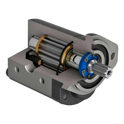
Components of Gear Pumps
Gears: Types and Functionality
Gears are the central element that help to move the fluid across the pump housing. The two major types of gears used in gear pumps are:
| Gear Type | Design | Advantages | Best Applications |
|---|---|---|---|
| External Gears | Two similar interlocking gears are laced side by side | Simple construction, ruggedness, and high-pressure efficiency | High-pressure conditions, heavy-duty operations |
| Internal Gears | Smaller inner gear meshing with a larger toothed outer gear | Better suction performance, lower pulsation | High-viscosity fluids like molasses, heavy oils, and polymers |
Housing: Structure and Material Considerations
The housing serves crucial functions: it aligns internal components, withstands operating pressure, and ensures leak-proof operation. Common materials include:
- Cast Iron: Preferred for durability, economy, and moderate wear resistance
- Stainless Steel: Used for corrosive conditions in chemical processing or food industries
- Advanced Polymers: Offer low weight and compatibility with corrosive or abrasive fluids
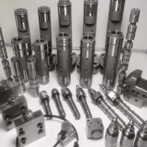
Shafts: Role in Pump Performance
Shafts are critical elements that decide overall performance, reliability, and efficiency. Acting as the central axis of rotation, they transmit torque from the drive to the gear set. Key considerations include:
- Material Selection: Hardened steel alloys or stainless steels for durability and corrosion resistance
- Precision Engineering: Necessary to decrease mechanical losses and maintain alignment
- Surface Treatments: Low-friction coatings to minimize energy waste and material degradation
Types of Gear Pumps

Internal Gear Pumps: Design and Advantages
Internal gear pumps feature two gears—a larger outer gear and a smaller inner gear that rotate to pump fluids. The inner gear is offset inside the outer gear, creating sealed cavities that carry fluid from the suction to the discharge side.
Key Advantages:
- Handle a wide variety of viscosities
- Self-priming capability
- Minimal pulsation and low shear
- Excellent leakage control
- Compact size and ruggedness
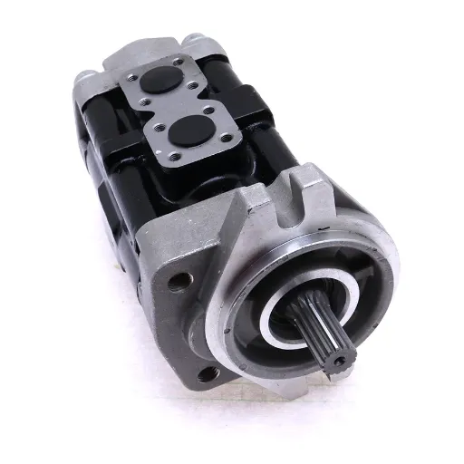
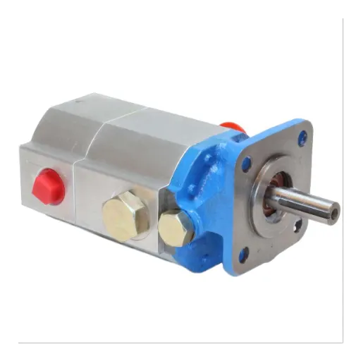
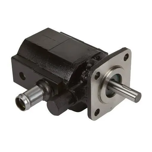
External Gear Pumps: Features and Benefits
External gear pumps use dual rotors with external teeth that rotate oppositely to displace liquid, entrapping it between the teeth and casing.
Key Benefits:
- Handle higher pressures effectively
- Compact design with fewer moving parts
- Precise flow rate determination
- Smooth, continuous flow with little pulsation
- Enhanced durability in harsh environments
Comparison of Internal and External Gear Pumps
| Aspect | Internal Gear Pumps | External Gear Pumps |
|---|---|---|
| Operation | Smooth, low noise, high volumetric efficiency | High-pressure handling, suitable for viscous fluids |
| Applications | Metering, food, hydraulic, pharmaceutical | Oil transfer, chemical processing, hydraulic systems |
| Flow Characteristics | Smoother flow, minimal pulsation | High flow rates, suitable for large industrial systems |
| Maintenance | More complex design | Simple, easy to maintain |
Common Issues and Troubleshooting

⚠️ Cavitation: Causes and Solutions
Causes:
- Restricted inlet flow
- High fluid viscosity
- Excessive pump speed
- Improper system design
Solutions:
- Proper pipe sizing and layout
- Maintain adequate fluid levels
- Stay within the manufacturer’s speed recommendations
- Use appropriate fluid viscosities
💧 Leakage: Identifying and Fixing Problems
Inspection Areas:
- Seals and gaskets for wear or misalignment
- Shaft wear and alignment
- Housing cracks and loose fasteners
- Operating pressure and temperature conditions
Solutions:
- Regular component replacement
- Precision alignment using laser technology
- NDT inspections for hidden defects
- Real-time monitoring systems
Maintenance Tips for Gear Pumps
- Lubrication Management: Use manufacturer-recommended lubricants and check periodically for contamination
- Component Inspection: Regularly inspect seals, bearings, and gears for wear or damage
- Operational Monitoring: Keep operating pressures and temperatures within design limits
- Preventive Maintenance: Replace components during planned maintenance to prevent unexpected shutdowns
- System Monitoring: Implement real-time monitoring for pressure, temperature, and performance parameters
Innovations and Trends in Gear Pump Technology
Advancements in Materials and Design
Latest improvements in material science and design processes have significantly enhanced gear pump performance:
- Advanced Materials: High-performance alloys and composite materials for better wear and corrosion resistance
- CFD Analysis: Computational Fluid Dynamics for optimized gear profiles and reduced cavitation
- 3D Printing: Additive manufacturing for complex custom components with high precision
- Smart Technology: Integrated sensors for real-time monitoring of flow rate, temperature, and pressure
Energy Efficiency Improvements
Modern gear pumps show up to 20% energy savings compared to predecessors through:
- Low-friction coatings to minimize mechanical energy loss
- Variable speed drives for dynamic operation adjustment
- Optimized flow passages to reduce turbulence
- Enhanced internal tolerances for better hydraulic performance
Digital Monitoring Systems
Digital monitoring systems have revolutionized gear pump operation by providing:
- Real-time Data: Continuous monitoring of pressure, flow rate, temperature, and vibration
- IoT Connectivity: Remote monitoring and data analysis capabilities
- Predictive Maintenance: Machine learning algorithms to identify potential issues
- Process Optimization: Long-term trend analysis for performance improvement