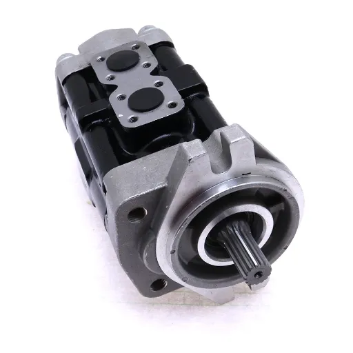
Understanding the intricate details of rotor pump diagrams is essential for engineers, technicians, and industry professionals who aim to optimize fluid handling systems. These diagrams serve as critical blueprints, visualizing the inner workings of rotor pumps and their role in maintaining efficient and reliable operations across various applications. Whether you’re troubleshooting performance issues, designing custom systems, or seeking to enhance your technical expertise, decoding these diagrams is a fundamental skill. This guide is designed to demystify rotor pump diagrams, breaking down their components, symbols, and functions with precision and clarity. By the end of this article, you’ll gain a comprehensive understanding of how to interpret and utilize these diagrams effectively, empowering you to tackle complex challenges with confidence.
What is a rotary vane pump, and how does it work?

Understanding the pump design
A rotary vane is a positive displacement pump that comprises a set of vanes fitted into a rotor for the transportation of fluid through the system. These vanes are fitted into slots machined into the rotor, sliding in and out of their slots as the rotor turns to always remain in contact with the interior walls of the pump. The continual change in volume of these chambers forces the fluid to be drawn in, compressed, and finally discharged through the pump.
The other main parts of the rotary-vane pump are the rotor, vanes, housing, inlet and outlet ports, and sometimes a seal. The rotor sits more or less in the center but is offset within the housing, causing the change in chamber volume. During rotation, centrifugal force, hydraulic pressure, or tension springs (depending on the design) will keep the vanes pressed outward against the walls of the pump. That very precise sealing and expansion allow the pump to provide reliable flow with a very low level of pulsation.
Due to their capacity to handle all sorts of fluids, including gases and liquids of intermediate viscosity, rotary vane pumps find applications in just about every trade. Typical applications include refrigeration, vacuum systems, and fuel transfer. Their efficiency and compact design give them an edge whenever pressure control and fluid transfer systems require precise control. Good maintenance of components such as vanes and seals is the basis for lasting reliability and performance.
The role of the rotor and stator in operation
In rotary vane systems, the rotor and stator have opposing roles that must work together for perfect operations. The rotor, centrally situated and usually eccentrically placed concerning the stator, holds the vanes that may glide outward by centrifugal force as the rotation proceeds. These vanes partition the internal chamber into separate compartments, permitting the swift movement of fluid from inlet to outlet and thus the establishment of the required pressure difference or maintenance of fluid flow.
The stator provides the stationary housing and structure within which the rotor operates. Its elliptical or cylindrical configuration serves in maintaining specific tolerances wherein the rotor and vanes can function to optimally compress and transfer fluid. Moreover, the precise geometric alignment of the stator is necessary to reduce the wear of components and sustain their consistent efficiency for long utilization.
These components of rotor and stator combine for the fundamental functioning of compression, pressure control, and fluid flow in rotary vane systems. From being lubricated to alignment and material quality, these factors guarantee minimal mechanical loss and stellar reliability under rigorous industrial-commercial setups. The operation of these components marks precision engineering as an important parameter for operational excellence.
How vanes mounted to a rotor facilitate fluid movement
Fluid movement in a rotary vane system is achieved through the creation of chambers inside the housing by the vanes mounted on a rotor. As the rotor turns, the vanes have a tendency to move radially with their slots, pressing against the housing wall either by centrifugal force, springs, or pressure in the system. As the vanes and rotor turn, varying compartments are created whose volume keeps varying.
Fluid enters through an intake port into the chambers that are expanding due to the movement of the vanes. As the rotor keeps spinning further towards the opposite phase of the rotor’s rotation, the shape of the chamber forces them to compress, which increases the pressure of the fluid. This compression and movement of fluid then directs the fluid toward the outlet port for regular and systematic discharge.
The efficiency of this system depends on proper engineering skills that help in reducing leakage and keeping pressure differentials at maxima. Appropriately sealing vanes between the rotor and the housing is thus very important for the system to achieve the highest efficiency. Due to their straightforwardness and dependability, coupled with ease in handling fluids of variable viscosities, these systems have found applications in hydraulic pumps, vacuum applications, and air compressors.
How do different types of rotary pumps compare?
Exploring various positive-displacement pumps
Positive-displacement pumps operate by trapping a fixed amount of fluid and then displacing it into the piping system. For this reason, they’re extremely useful when an application requires a constant flow under changing pressures. Large categories of special types of this kind of pump include rotary and reciprocating, each with its characteristics, working methods, and applications.
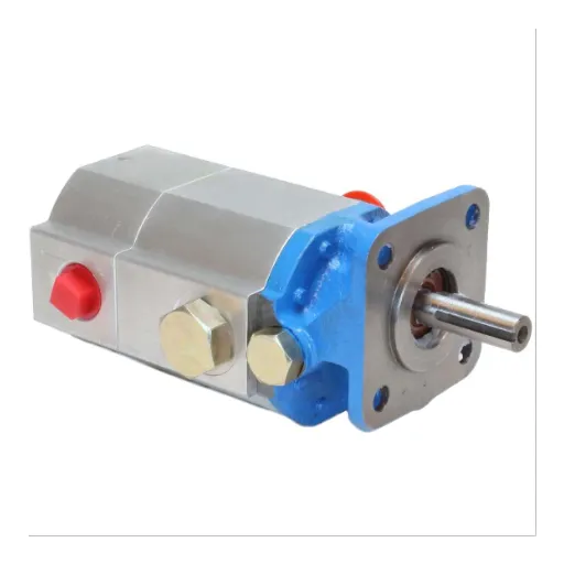
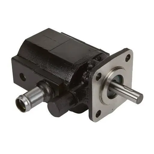
- Rotary-Positive-Displacement Pumps: With a rotary pump, the fluid is continuously moved by the ongoing rotation of one or more working members. The pumps generally consist of gear, vane, and screw types. Gear pumps use the rotation of two intermeshing gears to trap a volume of fluid, carrying it from the gear inlet to the outlet. This gives the pump super-high reliability and greater efficiency in pumping viscous fluids. The vane pump, as previously described, is ideal when the application requires a gentle flow with very accurate pressure control since the vanes slide in and out so that their outer edge always contacts the contour of the housing. Conversely, screw pumps use the relative motion of two or three intermeshing screws to enable the smooth flow of fluid, giving an advantage when faced with high-pressure demands, especially with fluids containing entrained gases. Their compactness and versatility in fluid type handling render them suitable for industrial applications.
- Reciprocating-Positive-Displacement Pumps: Reciprocating pumps move fluid by piston, plunger, or diaphragm operating in an alternating/pulsating manner. These pumps are characterized by the capability of generating high pressure and by accurate metering, and hence are found performing in oil and gas, chemical, and water treatment industries. Piston pumps can maintain constant pressure at high flow rates, whereas diaphragm pumps are designed for corrosive or abrasive fluids with their non-metallic wetted surfaces. Plunger pumps have excellent pressure performance even under severe conditions and find extensive use in hydrostatic testing.
A rotary-type pump has different characteristics than does a reciprocating-type pump. Which pump to choose for an application largely depends on fluid properties, operating pressures, and flow requirements, as well as other factors pertaining to industrial applications.
Differences between rotary vane pump and rotor pump
The difference between rotary vane and rotor pumps is mainly that the former relies on sliding vanes to move fluid and is generally considered independent, while the latter essentially depends on synchronized rotors and options a backing.
Summary of the major differences:
|
Aspect |
Rotary Vane Pump |
Rotor Pump |
|---|---|---|
|
Operation |
Sliding vanes |
Synchronized rotors |
|
Autonomy |
Works independently |
Requires support |
|
Fluid Handling |
Low viscosity |
Wide range |
|
Performance |
Moderate |
High |
|
Startup Speed |
Moderate |
Quick |
|
Power Usage |
Moderate |
Low |
|
Upkeep |
Moderate |
Minimal |
|
Use Cases |
Vacuum tasks |
Industrial settings |
Key characteristics of a vacuum pump
The vacuum pump is an important piece of apparatus. It removes air and other gas molecules from a volume that is sealed, creating a vacuum for industrial, scientific, and technical processes. The main parameters characterizing a vacuum pump include operational principle, efficiency, and suitability for a specific application:
- Pumping Speed and Capacity: The characteristics are given by the pumping speed of the vacuum pump, in volume units per time, such as liters per second or cubic meters per hour. It defines the rate at which the pump evacuates the system and consequently specifies its use in high-throughput operations.
- Ultimate Pressure: The minimum level of pressure as produced by a vacuum pump is said to be the ultimate vacuum, which is an important factor when environmental control needs to be held at precision. The difference lies in to pump type, rotary vane pumps achieving near-medical vacuum ranges, while turbomolecular pumps can go up to ultra-high vacuum.
- Gas or Vapor Tolerance: This is an important feature in terms of preventing adverse effects on the pump due to gases, vapors, or contaminants. Some pumps, such as dry screw pumps, are designed to handle corrosive or condensable materials, hence affording safety and durability in harsh environments.
- Energy Conservation: Modern-day vacuum pumps are optimally designed with power consumption in mind, so that they can run on low power without affecting performance. This is especially important in cutting down operational costs in industries that are heavy on power.
- Maintenance Considerations: Frequency of maintenance and ease of servicing of the vacuum pump have to be considered. For example, oil-sealed pumps require oil changes fairly regularly, whereas dry pumps have less maintenance and longer intervals of operation.
- Application Versatility: The vacuum pumps are built for an extensive range of uses-from semiconductor manufacturing to powering medical equipment. Their versatility is based on precision mechanical design and adaptability to diverse operational requirements.
These technical combined with choosing the right vacuum pump, guarantee efficient processes, system reliability, and the reaching of target vacuum levels in respective applications.
What are the advantages of using a rotor pump?
Benefits of low-pressure operation
Low-pressure operation in rotor pumps brings with it many advantages that improve efficiency and performance in various industrial applications. Here are the five principal benefits, along with their direct effects:
- Better Energy Efficiency: The system consumes less energy with low pressure than with high pressure for optimum performance. Studies have shown that low-pressure systems reduce energy costs by up to 30%, which adds to savings and promotes sustainable practices.
- Better Process Control: Low pressure permits more precise control of vacuum levels that are essential under processes that require stable conditions, such as chemical vapor deposition (CVD) or freeze-drying technologies. This control would limit variability and improve the product quality.
- Longer Equipment Life: With lower mechanical stresses and less thermal loads imposed on various elements of the pumping system, wear and tear are considerably less, thus extending the operational life of the equipment. It has been suggested by data that a low-pressure system can extend its life by around 20-25% in comparison to a high-pressure one.
- Reduced Heat Generation: Higher pressure levels produced more heat; therefore, lower pressure means less heat is produced. Since the heat load on equipment and systems surrounding it is reduced, lowered pressure can reduce the risks of heat-induced downtime and thus improve their reliability.
- Lower contamination risk: Maintenance of low-pressure levels significantly reduces the chances of contaminant backstreaming or infiltration within the process. This contamination would be of utmost risk in processes as semiconductor manufacturing, where purity stands critical for performance and yield optimization.
Together, these benefits would make low-pressure rotor pumps an ideal choice for industries that require precision, reliability, and efficiency.
Why rotor pumps are ideal for high-viscosity fluids
The design and the operating principles make rotor pumps most suitable for handling high-viscosity fluids. Thick, sticky substances can be transported in a controlled manner by the positive-displacement mechanisms of rotor pumps without any change in flow rate. In contrast to centrifugal pumps that depend on quick speed rotation, the lower RPMs offered by rotor pumps discourage shear stress, thereby preserving the essence of the fluids if they are sensitive.
Conversely, these pumps could create a steady flow rate regardless of the viscosity of the fluid or pressure alterations, hence giving outputs that are necessary in industries such as food manufacturing, pharmaceuticals, and adhesives making. Additionally, with the high, tight clearances inside rotor pumps, internal backflow is greatly decreased, assuring the best efficiencies for fluids with viscosities over 100,000 centipoise (cP).
The design of rotor pumps supports CIP (Clean-In-Place) and SIP (Sterilize-In-Place) procedures, making them easy to clean without taking apart, a strong selling point for hygienic applications. The materials of manufacture, which could be stainless steel or some specialized coatings, also guarantee longevity when working against abrasion or corrosion. They combine to make rotor pumps, opposite to any industry-dependent application, essential for the accuracy in handling viscous materials.
Understanding the self-priming capability
Separation of inadequate suction underlays some noteworthy self-priming features being incorporated into new concept rotor pumps for effective fluid transfer. This function is based on the pump’s capability to create and sustain a vacuum so as to suck liquid without externally priming it or manually augmenting the pressure. A few of the commonly used mechanisms involve recirculating some liquid in the casing to eject air from the suction line to ensure continuous operation.
With the evolution of pump technology, self-priming efficiency has been improved by newer and better designs for pump impellers, casing geometry, and sealing that reduce wear and energy loss during operation. For example, according to studies, new-generation self-priming pumps can prime up to 3-8 meters, depending on fluid viscosity and the environment of the specific application. This is important for industries like sewage waste handling, food processing, or chemicals. Fluid handling without downtime is what ensures the integrity of these processes. By using self-priming rotor pumps, issues such as downtime, contamination risk, and the general drive for automation and efficiency could be mitigated.
Coupled with precise design, rotor pumps can now be used on some difficult tasks such as pumping viscous, abrasive, or gas-containing fluids while coping with a wide range of working conditions. As such, they are dependable and versatile solutions for current industrial applications.
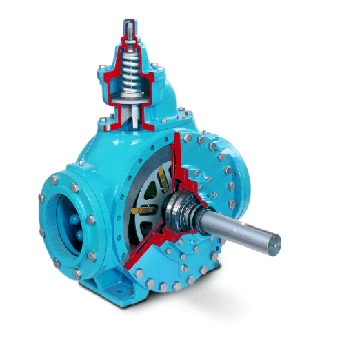
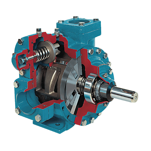
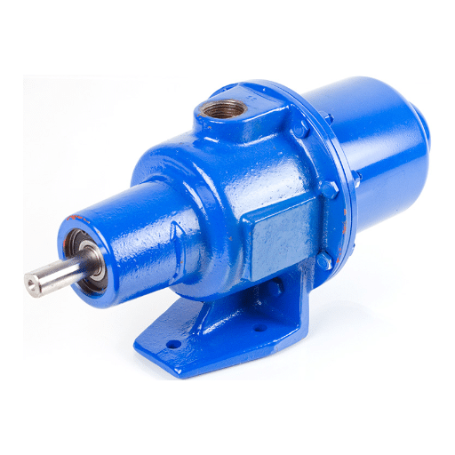
How does the diagram of a rotor pump explain its functionality?
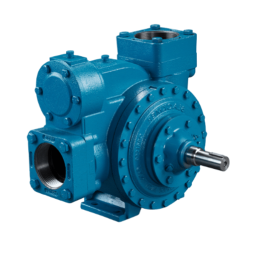
Anatomy of the pump chamber
In a nutshell, a rotor pump diagram shows how it works by depicting a rotor and stator with a chamber structure that permits the fluid flow. To me, this representation simplifies complicated fluid mechanical intricacies and provides insight into how motion and pressure are developed in the system.
Likewise, the pump chamber is constructed in such a way that its characteristics favor the optimum flow of substances with whatever difficult characteristics, such as high viscosity or abrasiveness. The surfaces inside the pump chamber are designed to minimize friction and wear so the pump may stay working efficiently over extended operating hours. Rotors, with their correlated motion, create pockets that trap fluid and displace it, ensuring the flow remains smooth and steady.
Furthermore, it is common for the diagram to show clearances and the spacing thereof to avoid backflow and improve volumetric efficiency. The portrayed visualization is, for me, an indispensable resource that draws attention to critical elements in functions such as sealing and flow paths, which render the operational principles of rotor pumps understandable and have direct applications in the real-world industrial scenario.
The flow of fluid through the inlet and outlet
The flow of fluid in rotor pumps is governed by the exact interaction between the individual rotors and the casing of the pump. The fluid enters the pump at the inlet due to the pressure difference. This pressure difference generally occurs due to the vacuum effect developed when the rotors rotate. The fluid is then carried by the rotors, which are designed with very tight tolerances; the fluid is situated in the cavities between the rotor lobes and the casing. This type of flow is steady and non-pulsating, characterized by the lowest turbulence level and shear; therefore, it would not destroy the fluid, which finds application in cases where sensitive fluids or highly viscous materials are to be handled.
Upon approaching the outlet, the rotor lobes close together to afford gradual compression towards the discharge port. This precise timing of the rotors minimizes backflow and provides steady flow rates. Primary clearance between rotors and casing is essential to maximize volumetric efficiency and minimize leakage or slip. Most crucially, this minimizes the energy losses common with other types of fluid transfer machinery, thereby rendering rotor pumps quite efficient in industries such as food processing, pharmaceuticals, and petrochemicals, where accuracy and efficiency are key.
Utilizing the capabilities of modern computational fluid dynamics (CFD) analysis and material advancements, modern rotor pump designs employ data-driven information to move toward further improvement in fluid transfer efficiency. For example, simulation during the design phase employs actual geometries to predict flow paths, optimize clearances, and assess the potential for cavitation. Such precision engineering, aided by data analytics, promotes a balance of the physical forces in the pump itself, increasing equipment longevity without compromising operational reliability. Developments such as these show how a detailed analysis, combined with mechanical expertise, can solve historical shortcomings of fluid dynamics in industries.
Interpreting the pressure changes within the cavity
Whatever be the kind of fluid system, more so, the high-pressure ones, cavity pressure changes occur due to the complex interplay of hydrodynamic forces and plate stresses. The cavities, be it in impellers, channels, or other components of the structure, undergo pressure changes, which can affect the overall performance of the system. These pressure fluctuations occur due to velocity gradients in the fluid, turbulence, or phase changes. If one thinks of the fluid accelerating in a small cavity, the pressure will drop according to Bernoulli’s theorem, and cavitation phenomena might take place. As such, cavitation implements a weathering effect with the vaporizing and collapsing of vapor bubbles.
Irrespective of whether the pressure fluctuations are those in the cavity, modern CFD software interfaced with a real-time monitoring system can now precisely keep track of them. By means of advanced simulations, engineers can identify zones within cavities at high risk where pressure drops may become critical. This is crucial relative to the prevention of cavitation, since areas of low pressure inside a cavity might go below the vapor pressure of the fluid on whose bubble initiation process starts. Continuous monitoring systems provide real-time data that feeds back into the validation of CFD predictions and consents to operational parameters within allowed tolerances. Hence, the entire setup acts as the best tool for predictive maintenance and for reducing unscheduled outages.
Understanding and correctly interpreting pressure gradients, therefore, is a component of system safety and not simply operational efficiency alone. Large pressure decreases or pressure spikes in turn may create stress concentrations that cause material fatigue or result in a sudden brittle failure. Analyses may be carried out on pressure data recorded over time to identify trends indicating the development of dangerous operating conditions. When cavity pressure data is subjected to machine learning, it can elicit patterns of prediction that provide engineers with actionable insight. In combination with high-resolution sensors and advanced diagnostics, this offers the means for industries to reduce risk, enhance equipment life, and better optimize fluid flow processes for multiple applications.
What maintenance is required for optimal rotary pump performance?
Routine checks for seal integrity
Seal integrity is paramount for the trouble-free operation of rotary pumps since leakage through damaged seals results in their reduced capabilities or total failure of the pump. The routine maintenance is comprised of visual inspections for wear and tear, cracks, abrasions, or deformations in either static or dynamic seals. Sometimes, accelerated degradation would result from slight misalignment or improper seating of the seals; hence, the positioning of the seals within the casing has to be confirmed. Therefore, secondary sealing elements such as O-rings and gaskets should be examined to prevent weak link formation within the overall seal integrity.
For the best maintenance, operators must also look for alterations in the pump’s fluid handling features from abnormally high-pressure drops or increased vibration levels, which indicate the seals may be deteriorating. However, taking measures with sophisticated diagnostic instruments like ultrasonic leak detectors or thermal imaging cameras will allow you to pinpoint seal problems that are not apparent on normal visual checks. Therein lies the plus point – minimizing downtime and solving minor faults even before they turn big.
The fusion of routine aspects with technologies such as condition monitoring based on sensors and AI analytics helps operators refine the exact point of spontaneous failure of the seal. By feeding in past data on operating conditions, material performance, and environmental factors, machine learning algorithms provide very informative data on when exactly a seal would require replacement or adjustment. This formidable combination of heavy data analysis effectively cuts down unplanned failures, ensuring maximum pump efficiency and lending support to extended operational life, all in the facets of rotary pumps, even within the harshest industrial environments.
Preventing friction and wear on rotor components
Rotor component friction and wear mitigation constitute the primary area of focus of modern mechanical engineering, particularly in heavy industry applications. Advanced engineering surface techniques, e.g., thermal spray coating or CVD, impart wear resistance by making rotor materials hard and resilient. Other types of lubricants are engineered with precision to match operational conditions so as to assure constant film formation to maintain separation between moving parts. Such lubricants contain friction-reducing additives such as molybdenum disulfide and PTFE, which under extreme loads or temperatures decrease the friction coefficient and increase the life span of the rotor system.
Computational simulations from the design perspective likewise take on a vital role in precluding wear issues. These simulate FEA methods to predict stress distribution and possible hot spots on rotor components so engineers can adjust geometry and materials accordingly before manufacturing. Employing self-lubricating composites in the rotor design enormously lessens dependence on manual lubrication in systems working in remote or out-of-reach areas.
These systems use sensor data fused with analytics to detect very early signs of wear, like vibration abnormality or exceedance of thermal thresholds. When these proactive steps are stitched with predictive analytics, the industries reap immensely through reduced downtime, higher efficiency, and in-process cost savings.
Ensuring shaft alignment and rotation efficiency
Shaft alignment is extremely crucial in ensuring that the rotating equipment is operating to its utmost efficiency and is attended to with longevity. When the centerlines of coupled shafts are not collinear, misalignment occurs, and undue stress is meted out through several machine components such as bearings, seals, and couplings. This stress would result in premature failures of equipment, unplanned downtime, and, most complicated, expensive repairs. To reduce these risks, precision shaft alignment techniques are deemed useful most times, with the laser alignment systems standing as the most recommended blocks of these techniques for their precision and repeatability. They provide measurements of angular and parallel misalignment with pinpoint accuracy, even if the rotational speeds are high, delivering the best rotational performance.
An important advance in the industry includes the integration of condition monitoring sensors with alignment instruments. The sensors provide data in real time pertinent to the operation of the machines, such as vibration levels, angular displacement, and temperature, which signal an alignment issue before it gets out of hand. Coupled with sophisticated analytics on the other side, this approach enables the maintenance team to automate diagnostics and administer data-driven corrections. Predictive maintenance automates the process of analyzing diverging data streams, past and present, to forecast plausible alignment deviations, which in turn would allow operators to take corrective actions ahead of time, simply avoiding expensive failures.
Then again, alignment has a direct impact on energy efficiency. In poor alignment, instances of increased friction and hindrance to the system arise, thereby making excessive demands on power. It is even reported in another recent research work that even small misalignments could cause 10% extra energy consumption. By using the newest alignment technology, industries can improve energy performance, reduce operational costs immensely, and satisfy sustainability goals. With technological advancement, the synthesis of IoT-enabled devices, machine learning algorithms, and precision engineering will herald the possibility where aligning shafts for peak efficiency may not just be the end of maintenance best practice but also near-complete automation.
Frequently Asked Questions (FAQ)
Q: What is a rotor pump diagram?
A: A rotor pump diagram is a schematic representation that illustrates the components and functioning of a rotor pump, highlighting the flow of liquid through its various parts, such as the suction and discharge sides.
Q: How does a rotor pump work?
A: A rotor pump operates by rotating an eccentric rotor inside a chamber, creating a vacuum that draws liquid into the suction side. This liquid is then directed through the chamber and expelled through the discharge side.
Q: What role does the valve play in a rotor pump?
A: The valve in a rotor pump controls the flow of liquid, preventing backflow and ensuring that the liquid moves efficiently from the suction side to the discharge side of the pump.
Q: Why are vane pumps commonly used in industrial applications?
A: Vane pumps are commonly used in industrial applications due to their ability to handle a wide range of viscosities, their efficiency in maintaining a consistent flow rate, and their suitability for two-stage operations.
Q: What is the significance of the eccentric design in rotor pumps?
A: The eccentric design in rotor pumps is crucial as it allows the rotor to create a variable chamber size, enabling efficient suction and discharge of liquids as the chamber reaches different volumes during operation.
Q: How does the inner wall of the chamber affect pump performance?
A: The inner wall of the chamber in a rotor pump is designed to fit closely with the rotor, ensuring minimal leakage and maintaining the pressure necessary for effective liquid transfer between the suction and discharge sides.
Q: What is the purpose of a bypass in a rotor pump system?
A: A bypass in a rotor pump system allows excess liquid to be diverted away from the main flow path, preventing overpressure and ensuring the pump operates within its designated parameters.
Q: How are rotor pumps used in dispensers and espresso machines?
A: Rotor pumps are utilized in dispensers and espresso machines to provide precise liquid control, ensuring consistent flow rates and pressure necessary for optimal beverage preparation.
Q: What is the function of the exhaust in a rotor pump?
A: The exhaust in a rotor pump is responsible for expelling air and vapor from the liquid in the chamber, facilitating smooth operation and preventing any potential blockages or pressure build-up.
Q: Why is the injection process important in rotor pumps?
A: The injection process in rotor pumps is vital for introducing additives or lubricants into the liquid flow, enhancing the performance and longevity of the pump by reducing friction and wear.