Keeping pace with modern industrial demands, hydraulic gear pumps have always been essential elements in most industrial and mechanical systems for efficient fluid transfer and pressure development. These versatile pumps serve various applications, from running heavy machinery and automotive systems to hydraulic presses and many other uses.
Introduction to Hydraulic Gear Pumps
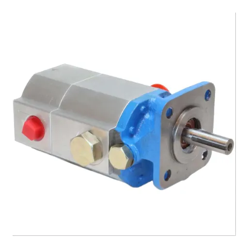
What is a Hydraulic Gear Pump?
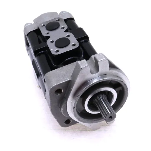
A hydraulic gear pump is a mechanism used to force hydraulic fluid into a system to create a flow that can be used to transmit power. Being a positive displacement pump means it conveys a fixed volume of fluid for every rotation of its gears. It finds wide usage in hydraulic systems for supporting various operations such as lifting, steering, and actuating.
Key Operating Principle: The pump creates pressure and flow through the meshing of gears. In most gear pumps, there are two gears – one drive gear and one idler gear. The two gears fit tightly within a casing to prevent fluid leakage while ensuring consistent, positive fluid flow regardless of system pressure.
Hydraulic gear pumps are valued for three key attributes:
- Simplicity – Straightforward design with minimal moving parts
- Sturdiness – Built to withstand high-pressure operations and harsh conditions
- Efficiency – Consistent performance with reliable fluid displacement
Importance of Hydraulic Systems
Hydraulic systems have found exceptional application in modern sectors due to their ability to convey substantial amounts of power through simple mechanisms. These systems use pressurized fluid to accomplish work, facilitating smooth movement and control of heavy loads.
Key Advantages of Hydraulic Systems:
- High Power-to-Weight Ratio: Generate enormous forces with compact components
- Precise Control: Accurate positioning capabilities are essential for aerospace and robotics
- Reliability: Operate effectively under adverse environmental conditions
- Durability: Minimal maintenance requirements compared to alternative power transmission methods
Applications of Hydraulic Gear Pumps
Hydraulic gear pumps find widespread use across industries, offering durability, accuracy, and high-pressure fluid system capabilities. Here are five major applications:
| Application Area | Equipment Examples | Key Benefits |
|---|---|---|
| Construction Machinery | Excavators, loaders, bulldozers | Reliable operation in harsh conditions, powerful hydraulic cylinder movement |
| Agricultural Equipment | Tractors, harvesters, sprayers | Measured flow with defined pressure for smooth field operations |
| Industrial Manufacturing | Hydraulic presses, molding machines, assembly lines | Continuous pressure for precision fabrication and automation |
| Material Handling | Forklifts, cranes, aerial platforms | Precise and safe lifting operations in warehouses and logistics |
| Marine & Offshore | Ship steering systems, winches, and deck equipment | Robust performance in hostile marine environments |
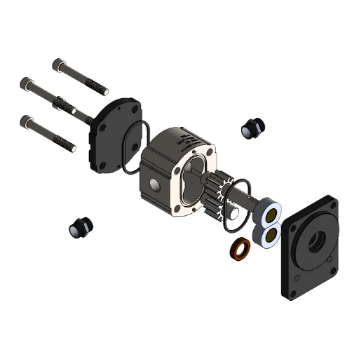
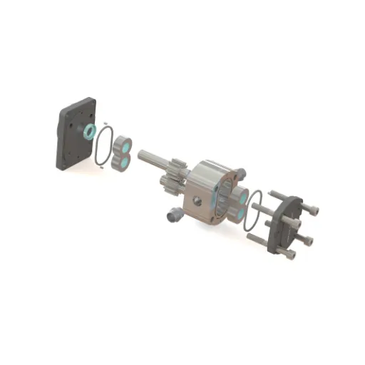
Components of Hydraulic Gear Pumps
Overview of Gear Pump Components
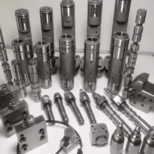
The primary components of a hydraulic gear pump work together in coordination to achieve efficient and accurate fluid displacement:
- Gears: Main working components, typically external gears consisting of driving and driven gears made from hardened steel or bronze alloys
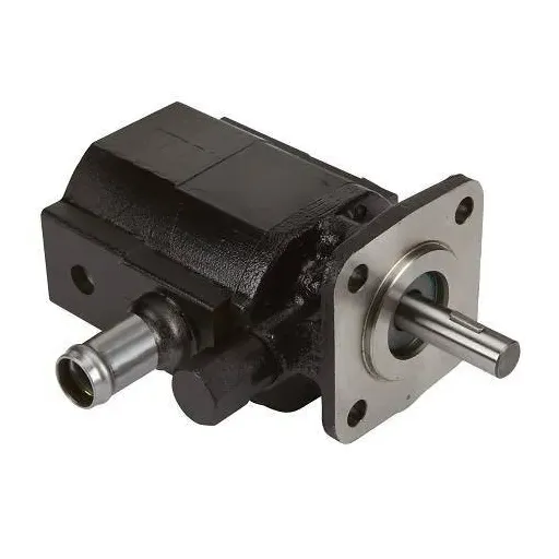
- Housing: Encloses gears and provides structural strength, cast in iron, aluminum, or steel, depending on application
- Shafts and Bearings: Connect the driving gear to the external power source with smooth rotation support
- Seals and Gaskets: Prevent fluid loss, made from elastomers or composite materials with superior chemical and thermal resistance
- Pressure Ports: Inlet and outlet ports designed for minimum pressure losses and reinforced for durability
- Relief Valve: A Safety feature that diverts excess flow when system pressure exceeds preset values
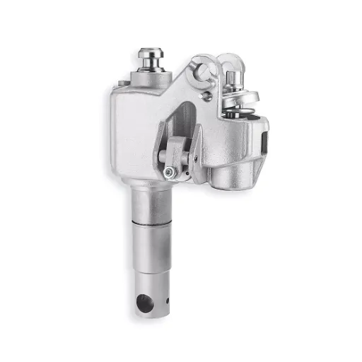
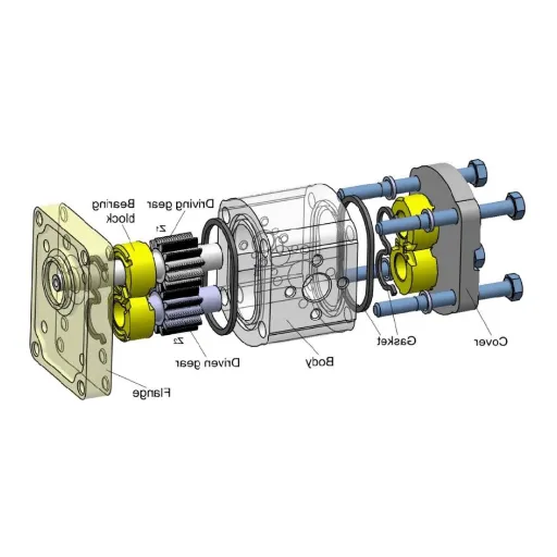
Understanding External Gear Configuration
External gear pumps feature two interlocking gears, creating controlled fluid displacement. The driving gear and driven gear rotate in opposite directions within a controlled housing, with fluid caught in pockets between gear teeth and the pump casing.
Performance Specifications:
- Operating pressure: 1,000 – 3,000 PSI
- Efficiency: Above 90% in most cases
- Materials: Hardened steel or composite polymer construction
- Capabilities: Bi-directional operation, electronic control system integration
Detailed Breakdown of Internal Components
Made from cast iron, aluminum alloys, or stainless steel. Protects internal mechanisms and maintains structural integrity under extreme pressures and temperatures.
Precision-machined spur and helical types made from hardened steel or composite materials for ideal meshing and efficient fluid transfer.
Constructed from nitrile rubber, PTFE, or Viton. Bearings made of bronze alloys or ceramic for durability and low friction.
Manage fluid flow and pressure with precision, featuring electrohydraulic or servo-actuated adjustments for real-time control.
Hydraulic Pump Performance
Factors Influencing Hydraulic Pump Efficiency
Hydraulic pump efficiency is influenced by mechanical, volumetric, and hydraulic factors:
- Mechanical Efficiency: Affected by internal friction from bearings and seals – minimized through better materials and lubrication
- Volumetric Efficiency: Impacted by internal leakage – prevented through high-tolerance manufacturing
- Hydraulic Efficiency: Dependent on fluid properties like viscosity and temperature
- Contamination Control: Particle removal through advanced filtration systems
- System Design: Proper pressure, flow rate, and component placement optimization
Performance Metrics for Gear Pumps
| Metric | Description | Typical Range/Unit | Importance |
|---|---|---|---|
| Flow Rate | Fluid conveyance capacity and velocity | GPM or L/min | Determines system capacity |
| Pressure Rating | Maximum operating pressure without failure | Up to 3,000+ psi | Defines application suitability |
| Volumetric Efficiency | Resistance to leakage and optimal transfer | Percentage (%) | Indicates machining quality |
| Power Consumption | Input energy requirement | kW or HP | Operating cost factor |
| Temperature Stability | Operation under thermal variations | °C or °F range | Long-term reliability |
| Noise Levels | Acoustic performance measurement | Decibels (dB) | Environmental compliance |
Common Issues and Troubleshooting Techniques
Troubleshooting Guide:
Low Flow Rate:
- Check for air entrainment in fluid
- Clean clogged inlet filters
- Ensure airtight suction lines
- Verify proper pump sizing
Noise and Vibration:
- Inspect for cavitation and air leaks
- Replace worn bearings
- Check shaft alignment
- Maintain proper lubrication
Overheating:
- Verify fluid viscosity specifications
- Ensure adequate lubrication
- Monitor system pressures
- Check for continuous high-pressure operation
Types of Hydraulic Pumps
Comparison of Hydraulic Gear Pumps and Other Types
| Pump Type | Pros | Cons | Best For |
|---|---|---|---|
| Gear | Compact, cost-effective | Noisy, lower efficiency | Moderate pressure applications |
| Vane | Steady flow, efficient | Requires good seals | Air conditioning systems |
| Piston | High-pressure, durable | Expensive, bulky | High-pressure tasks |
| Screw | High efficiency | Costly, complex | High flow/pressure applications |
| Centrifugal | Handles low viscosity well | Poor for high viscosity | Low-viscosity fluids |
External Gear Pumps vs. Internal Gear Pumps
| Aspect | External Gear | Internal Gear |
|---|---|---|
| Pressure Range | High | Moderate |
| Fluid Viscosity | Medium | High |
| Heat Tolerance | Medium | High |
| Cost | Lower | Higher |
| Size | Compact | Bulkier |
| Flow Direction | Uni/Bi-directional | Bi-directional |
| Use Cases | Fuels, chemicals | Resins, bitumen |
Choosing the Right Hydraulic Pump for Your Application
- Pressure and Flow Requirements: Determine operating pressure and desired flow rate for proper pump selection
- Fluid Characteristics: Consider viscosity, lubricating properties, and contamination levels
- Temperature Limits: Assess thermal requirements and heat dissipation needs
- System Design: Evaluate space limitations and dimensional constraints
- Cost vs. Longevity: Balance initial investment against long-term durability
- Specific Application Needs: Consider bi-directional flow requirements and operational complexity
Real-World Applications of Hydraulic Gear Pumps
Case Studies in Industrial Settings
Case Study 1: Enhancing Efficiency in Manufacturing Lines
A large automotive company experienced constant delays due to erratic hydraulic performance in assembly line equipment. After implementing external hydraulic gear pumps designed for continuous heavy-load operation, the plant achieved:
- 23% improvement in efficiency
- Significant reduction in downtime
- Lower maintenance costs due to enhanced reliability
Case Study 2: Agricultural Sector Optimization
Agricultural machinery requiring robust hydraulic systems chose bi-directional hydraulic gear pumps for their tractors, resulting in:
- 15% enhanced efficiency
- 30% longer operational life
- Extended service intervals with fewer operational interruptions
Case Study 3: Hydraulic Systems for Marine Operations
Fishing fleet operations in harsh marine environments implemented corrosion-resistant internal gear pumps for onboard winch systems, achieving:
- 35% reduction in equipment failure rates
- Enhanced operational predictability
- Significant cost savings in maintenance and repairs
Future Trends in Hydraulic Pump Technology
Emerging Technologies:
- Electro-hydraulic Systems: Integration with digital control units for real-time performance adaptation
- Advanced Materials: Lightweight composite materials for aerospace and automation applications
- Eco-friendly Solutions: Pumps designed for biodegradable hydraulic fluids
- Predictive Maintenance: Embedded sensors for monitoring pressure, temperature, and wear patterns
- Modular Designs: Standardized, interchangeable components for rapid customization
Frequently Asked Questions (FAQ)
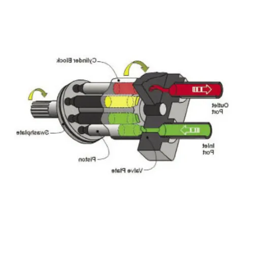
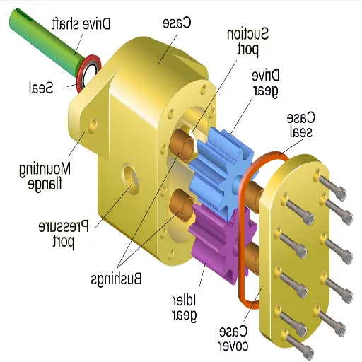
A: A hydraulic gear pump diagram is a pictorial representation of the components, operation, and flow paths of a hydraulic gear pump. These diagrams help users understand pump functioning in hydraulic systems, emphasizing gear setup and hydraulic fluid flow.
A: The hydraulic gear pump operates through gear meshing, creating a vacuum at the pump inlet to draw hydraulic fluid into the pump chamber. Gear rotation transfers fluid to the discharge side, forcing it toward the pump outlet to produce an adequate flow rate for various hydraulic applications.
A: Main types include gear pumps, vane pumps, piston pumps, and screw pumps. Each type performs the fundamental task of converting mechanical power into hydraulic energy for different hydraulic system requirements.
A: Fixed displacement pumps deliver a constant flow rate regardless of system pressure changes, while variable displacement pumps adjust flow rate according to hydraulic system needs, providing optimal hydraulic power and improved system efficiency.
A: Volumetric efficiency relates to how well the pump converts input power into hydraulic energy. Higher volumetric efficiency means less hydraulic fluid loss, enhancing performance and reducing operating costs of hydraulic systems.
A: External gear pumps have two gears that mesh outside the pump casing, while internal gear pumps have one gear located inside another. This creates different flow patterns, with internal gear pumps generally providing better suction capabilities.