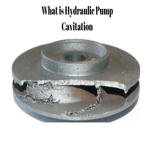
Hydraulic pump cavitation is a critical issue that can lead to significant performance losses, costly repairs, and even equipment failure if left unchecked. This phenomenon, caused by the formation and implosion of vapor bubbles within a hydraulic system, poses serious challenges to maintaining the efficiency and longevity of machinery. Understanding the root causes of cavitation, recognizing its early warning signs, and implementing effective prevention strategies are essential for preserving the integrity of hydraulic systems. This article will take a deep dive into the complexities of hydraulic pump cavitation, providing you with valuable insights into its causes, the detrimental impact it can have on your equipment, and actionable steps to mitigate this damaging process. Stay tuned to equip yourself with the knowledge needed to protect your hydraulic systems and maximize operational reliability.
What is Hydraulic Pump Cavitation?
Defining Cavitation in a Hydraulic System
Such an occurrence in a hydraulic system involves both the formation and collapse of vapor bubbles in a fluid. It occurs once the pressure in the system drops beneath the fluid’s vapor pressure. The liquid hence vaporizes at low-pressure points. However, the bubbles, through their journey in the system, move into a high-pressure area, and they blast violently, thereby generating shockwaves of considerable magnitude. These implosions then seriously damage system components such as hydraulic pumps and valves.
Cavitation is caused by hydraulic fluid being inadequately supplied to the pump, large restrictions in the suction line, or entrained air in the hydraulic fluid. Filters and strainers may be blocked, suction lines may be improperly sized or routed, or the reservoir level may be too low, all of which could result in cavitation-inducing pressure conditions. Elsewhere, inappropriate pump speed or application of the fluid outside its operating temperature range could worsen the problem, eroding the reliability of the system even further.
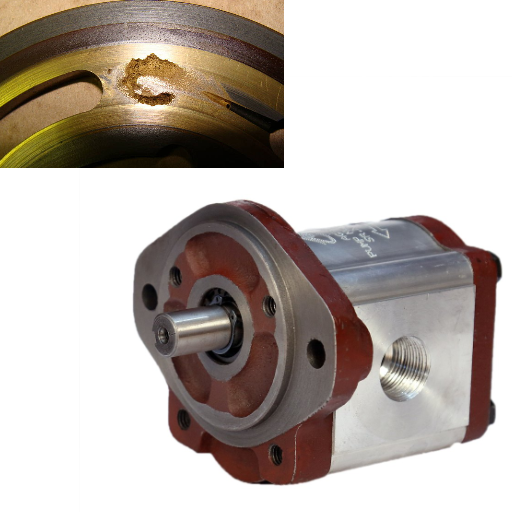
Cavitation does all kinds of harm to hydraulic system performance. Repeated implosion of vapor bubbles, in the long run, also erodes metal surfaces, thereby causing pitting and wearing out of all the critical components. This process greatly reduces the effectiveness of the hydraulic pump and the risk of sudden equipment failure. Immediately recognizing cavitation occurrences by their various symptoms is a critical step to precipitating early intervention to minimize permanent damage. Some of these symptoms are peculiar noises, usually described as gravel noises, reduced efficiency of the system, and erratic operation.
How Cavitation Occurs in Hydraulic Pumps
In-water pump cavitation is formed when the internal pressure in the pump falls beyond the vapor pressure of the hydraulic fluid, causing vaporization of the fluid and the formation of vapor bubbles. These vapor bubbles are carried through the system until they reach a high-pressure area, where they collapse violently. The rapid implosion produces severe localized forces that destroy the internal components through erosion and hence reduce the operational efficiency.
The major causes of cavitation are blocked flow, low reservoir levels, highly viscous fluids filling the pump, or some degree of pressure imbalance in the pump evoked by clogged filters. One of the most common reasons for the pressure falling below the vapor pressure to start bubble formation is insufficient fluid flow to the pump inlet. Apart from the inlet flow issues, cavitation becomes even more likely for reasons other than cavitation: running the pump too fast or having poorly designed hydraulic lines that give rise to turbulence.
In terms of preventing cavitation, one should follow the right operating conditions in which the fluid levels are correct, appropriate filters are used, and all inlet lines are checked for blockages or leaks. On the other hand, choosing hydraulic fluids of the correct viscosity range and ensuring that the design of the hydraulic system encourages good flow of the fluid will also go hand in hand. Early prevention of cavitation averts damage and lengthens the life and efficiency of hydraulic pumps.
The Role of Bubbles in Cavitation
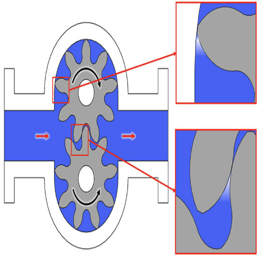
The formation and dynamics of bubbles largely govern the cavitation process. Cavitation ensues when the local pressure within a hydraulic system plummets below the vapor pressure of the fluid, causing the formation of vapor bubbles. Such bubbles are generally formed in high-velocity-low-pressure zones like those near impellers or valve restrictions. Hence, it is essential to know the conditions leading to bubble formation to forestall cavitation and its effects upon hydraulic systems.
When they form, the bubbles proceed to a region of very high pressure within the system, where they implode as the pressure grows exponentially in the small area and at the high temperature created by bubble collapse, damaging metal surfaces and other critical components in the long run. That collapse can really do some damage, but it also causes vibrations and noise as telltale signs of cavitation. Monitoring for these will greatly assist in identifying cavitation before it grows into serious problems, which can be costly to fix or could lead to a system failure.
Beyond the mechanical attack on surfaces, bubble activity associated with cavitation disturbs fluid flow and leads to a drop in system efficiency. The vapor bubbles displace the hydraulic fluid, thereby reducing its ability to transmit energy. Over time, though, further cavitation can damage system components so that they have to be repaired or replaced periodically. By means of controlling fluid pressure, flow velocity, and operating temperature, one can reduce bubble formation and hence the cavitation of hydraulic pumps. Great measures in system design should be taken to avoid cavitation problems, and regular maintenance must be undertaken to deal with any cavitation problems that do develop.
Identifying the Causes of Cavitation in Hydraulic Pumps
Common Causes of Cavitation
Cavitation occurs mainly when some sudden changes in pressure are allowed to create and then collapse vapor bubbles in the system. Usually, this happens because of certain peculiar operating conditions and design flaws in equipment. If we want to prevent damage and promote system efficiency, there needs to be an understanding of these causes.
Very frequently, cavitation is caused by excessive velocity or flow rate of fluid. When the fluid velocity is too high through a system, the pressure at some point, such as at the inlet of a pump or in a restriction, drops below the vapor pressure of the liquid, thus permitting the formation of vapor bubbles, which collapse further downstream when the pressure rises again. Behind these collapses stand forces whose magnitude is so great that they are capable of damaging the surfaces of equipment.
Another cause is improper system design or component selection. Dyeing impellers, valves, or pipework badly can cause nonuniform pressure distributions, thus making areas where cavitation can take place. High temperature operations also promote cavitation since at such temperatures the fluid vapor pressure is decreased, favoring bubble formation. Proper system maintenance and observance of good design standards can go a long way in alleviating these hazards.
Understanding the Cause of Hydraulic Pump Failures
There can be numerous reasons for failure in hydraulic pumps, each affecting the system performance differently. Most commonly, the failure is due to contamination of the hydraulic fluid. Solid particle contamination-from dirt, metal shavings, or ingress of water-can damage a pump’s interior surfaces, attacking them as abrasives for premature wear, inefficient operation, and finally failures. Even very fine abrasive particles can damage seals, bearings, and pistons to the point that the effective working life of the whole system is greatly reduced.
Another major cause of the incidents of pump failure is overheating. Excessive heat destroys hydraulic fluid; fluids lose their viscosity and cannot lubricate adequately; moving parts are worn at an increased rate and become thermally damaged; mechanical seals and hoses are thermally damaged; and so forth. Operating for even several hours with inadequate cooling compounds the situation, spawning an entire cascade of failures throughout the hydraulic circuit.
Obviously, failure can also be brought about due to improper system design or installation. Incorrectly sized pumps, misaligned components, or improper torque settings can put additional stresses on the pump. Likewise, inefficient filtration systems that do not trap particulates before they enter the pump present greater chances of damage.
Improved maintenance, as well as engineering excellence, must be brought to bear if these problems are to be studied. Reduction of hydraulic pump failures through fluid analysis, cooling mechanism maintenance, and adherence to filtration and system design recommendations set out by the OEMs will, in turn, protect system reliability and efficiency.
The Impact of Pump Inlet Conditions
From my standpoint, the pump inlet conditions are critical factors affecting the overall performance and service life of hydraulic systems. Proper inlet conditions will achieve the most efficient operation of the pump and the highest probability against damage caused by cavitation, hence affecting its performance and eventual failure. The essential considerations towards maintaining proper inlet conditions are enough inlet pressure, no air entrainment, and inlet line sizing. If these considerations are met with precision, system reliability will be increased manifold.
On the other hand, I strictly adhere to OEM guidelines for pump inlet design and maintenance to stay away from potential problems. In this, we try to ensure that the inlet line is not restrictive or poorly designed, as this would cause a reduction in pressure at the pump intake and induce cavitation. I also ensure regular inspections of the system to identify and rectify potential causes of contamination or air ingress that could compromise hydraulic fluid quality. Care toward inlet condition will reduce inefficiencies during operation and subsequent expensive repairs.
Furthermore, I take an active role in implementing additional best practices, including advanced filtration solutions and temperature control methods. These help to complement proper inlet conditions for the preservation of fluid integrity and system temperature. In my view, working on and optimizing pump inlet conditions is more than just a maintenance issue. It certainly is a very strategic intervention for extending the system’s lifespan and achieving optimum operational efficiency.
How to Prevent Cavitation in Hydraulic Systems

Effective Techniques to Prevent Cavitation
The formation of vapor bubbles inside a liquid due to pressure change can drastically reduce pump performance and shorten the life of other fluid-handling systems. There are a few techniques proven to work against cavitation, all of which have been extensively studied from fluid dynamics and mechanical engineering perspectives.
- Optimal System Design: Based on this logic, cavity prevention starts at the design phase; thus, it is essential to design pumps, valves, and hydraulic systems in such a way as to avoid abrupt changes in fluid velocity or pressure. For the prediction of cavitation-prone areas in the system and accordingly for their mitigation before implementation, one of the very powerful tools that can be used is CFD modeling. The use of impeller designs that give improved flow profiles and larger eye areas helps in reducing pressure drops, in particular.
- Adjusting Operating Conditions: Adjusting operating conditions and preventing cavitation during dynamic loads is the second line of defense against cavitation. These means should prevent excessive flow rates and maintain the Net Positive Suction Head Available (NPSHa) always above the Net Positive Suction Head Required (NPSHr). Properly adjusting both parameters will reduce the chance of pressure in the liquid dropping down to its vapor pressure.
- Material Selection and Surface Treatment: Making use of materials resistant to cavitation, such as duplex stainless steels or bronze alloy, can reduce damage due to bubble implosion. Besides, the application of surface coatings or surface treatments such as thermally sprayed ceramics or polymer composites will help reduce erosion in areas susceptible to cavitation.
- Selecting Suction Pipe: Selecting suction pipes with smooth transitions and avoiding obstructions is of the other prime method for cavitation prevention. Longer straight pipe sections before the pump inlet can be incorporated while avoiding sharp bends or abrupt contractions to help keep fluid stabilization and pressure consistency high.
- Pressure and Temperature Control: Maintaining steady inlet pressure and regulating fluid temperature within acceptable ranges keeps the liquid above vapor pressure. The issue is more pronounced in high-temperature conditions where a liquid tends to vaporize at a lower pressure, thus making cavitation more likely.
These techniques have been pieced together to become a comprehensive roadmap for cavitation management and prevention from industry best practices and analytical enhancements. If followed methodically, these techniques can grasp the service life extension of equipment and, consequently, better overall system efficiency.
Maintaining Optimal Hydraulic Fluid Levels
It is necessary to record measurements for optimizing fluid levels and following standard procedures meticulously. Hydraulic pressure is maintained with an accurate volume of fluid being present to lubricate moving parts and dissipate heat. Less fluid creates cavitation in the pump, thereby raising heat formation and decreasing the life span of the component. Higher levels of fluid lead to foaming, pressure imbalance, and contamination risk due to overflow.
Periodic inspections should confirm the hydraulic fluid level according to manufacturer specifications, which usually include considerations for thermal expansion. Modern hydraulic machines usually have sensors that constantly monitor fluid levels and alert the operator whenever a deviation is detected, giving a more proactive approach to maintenance. The operator should additionally ensure the fluid viscosity index is within the operating temperature ranges of the system, lest it degrade or become inefficient.
Another equally important aspect is contamination control for hydraulic fluid quality. If operators use the best filtration systems and have periodic fluid analysis, they can readily identify fine particles, water, and other contaminants. With this data, they can decide on fluid replacement or any corrective action to maintain hydraulic system reliability and performance.
These recommendations allow facilities to decrease operational risks significantly and extend the service life of hydraulic equipment, guaranteeing operational efficiency even under severe working conditions.
Ensuring Proper Pressure at the Pump Suction
The proper pressure at the pump suction is critical to maintain hydraulic systems efficiently and for a longer period. Insufficient suction pressure, what is more correctly termed cavitation, can bring about serious damage to the pump, such as erosion of internal parts and, thus, reduction in operational reliability. To safeguard against these risks, detailed parameters are to be monitored and balanced.
The NPSH, first and foremost, must satisfy system requirements. NPSHa (available) has to be greater than NPSHr (required) to avoid the formation of vapor bubbles in the pump. This may be realized by limiting the elevation difference between the source of fluid and the pump, flow restrictions, or ensuring proper viscosity for the fluid at operating temperatures.
Secondly, the designers have to consider pipe diameters and consequent pressure drops, trying to minimize bends, kinks, or anything that might cause unnecessary pressure losses. The filtration must also be suitable to stop any debris from impeding fluid flow at the pump inlet, thus guaranteeing a constant suction pressure.
Thirdly and most importantly, frequent checks are to be made on seals and connections to ensure that any ingress of air that may affect the pressure equilibrium is eliminated. By observing these technicalities, operators can prevent failures of a hydraulic system caused by improper suction pressures.
Recognizing Cavitation Symptoms and Damage
Signs of Cavitation in Hydraulic Systems
There are a few ways to recognize cavitation symptoms inside hydraulic systems. If these signs are neglected, the system itself can suffer from severe degradation, and components can fail. One of the prime symptoms can be described as an onset of unusual noise. Often, the louder noise is described as a consistent “gravel” or “popping” sound coming from the pumps or valves. It occurs when vapor cavities form and collapse inside the fluid, so micro-explosions occur.
The ineffective operation of hydraulic systems is another indication. Reduced flow rates or pressure levels might occur, indicating that movements in the fluid are being restricted by cavitation. Cavitation may also cause localized overheating, thereby increasing the thermal stress on the parts concerned. For instance, hydraulic systems might showcase abnormally elevated temperatures due to inefficiencies caused by vapor generation.
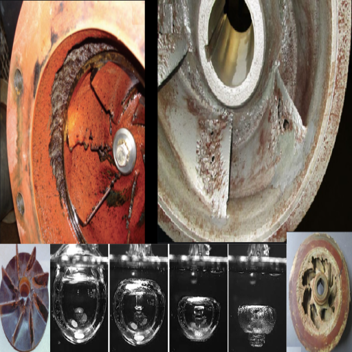
Physical manifestation of cavitation includes pitting or erosion on components of the pump, such as impeller or valve surfaces. Indications are obvious upon inspection and represent the destructive nature of cavitation. Any unexpected instability in system operation, pressure spike, and the like must trigger a detailed investigation for cavitation problems.
Keeping an eye on cavitation ensures early detection and thereby early remedy; thus, operating reliability and longevity of the hydraulic system are enhanced.
Assessing Damage to Hydraulic Pumps
Damages to hydraulic pumps must be evaluated systematically, examining both internal and external parts to ascertain the extent of the damage and the exact causes of wear or failure. Major parts to examine include pump housing, seals, and internal parts, including pistons, gears, or vanes, depending on the pump type. Any evident signs of damage could be in scoring, pitting, or erosion of surfaces where cavitation or contamination may maybe played a role. These conditions generally arise from air or vapor pockets, abrasive particles in the hydraulic fluid, or if the pump surface insufficient lubrication.
An analysis of this nature should consider performance data to assess for inconsistencies. For instance, decreasing volumetric efficiency or an abnormal amount of heat generated during operation could indicate internal damage. There are devices, such as ultrasonic sensors or infrared thermography, which can be used for the purpose of identifying irregularities without necessitating disassembly. Sampling the hydraulic fluid may also reveal the presence of debris or contaminants that might correlate with wear patterns.
When combined with their maintenance histories and real-time monitoring systems that provide key operating performances, these assessment methods raise the degree of diagnostic accuracy. Predictive maintenance tools integrated with advanced analytics further associate with isolating root causes to ensure that repair strategies are effective and evidence-based.
Diagnosing Hydraulic Pump Cavitation Issues
Hydraulic pump cavitation results in a critical caseload that significantly impacts the system’s functioning, efficiency, and working life. To diagnose cavitation, one must understand its factors, symptoms, and interference with a hydraulic system. Pressure drops below the vapor pressure of the fluid locally, leading to the formation of vapor bubbles of the hydraulic fluid is known as cavitation. These bubbles collapse as pressure increases, sending shockwaves which could inflict a great deal of destruction, such as to impellers, vanes, and housings of the pump.
Key cavitation symptoms are excessive noise, sometimes a high-pitched whining or knocking sound, abnormal vibrating sensations, and decreased system performance. An inspection of hydraulic components might also reveal signs of metal surface pitting or erosion, whereby the metal surface is eroded due to successive implosions of vapor bubbles. The use of sensors that monitor pressure flows can also aid in detecting cavitation, as irregular pressure drops are usually a major precursor.
Analytic techniques like fluid analysis further help detect contributing factors; for instance, the presence of entrained air, excessive water, or incorrect fluid viscosity levels can worsen cavitation conditions. Also, operators will be able to isolate root causes by using real-time analytics from integrated monitoring systems to analyze factors such as inlet pressure, temperature, and flow rates. With the above-mentioned tools and techniques, operators can deploy targeted remedial actions such as correcting the fluid level, ensuring sufficient inlet pressure, or replacing damaged components to fully halt ongoing damage, after which the system can be restored to full integrity.
Troubleshooting Hydraulic Pump Cavitation Problems
Step-by-Step Guide to Troubleshooting Hydraulic Cavitation
Hydraulic cavitation starts when vapor bubbles begin developing in a hydraulic system due to a decrease in pressure below the vapor pressure of the fluid. This kind of situation can cause damage to components through erosion, loss of efficiency, rise in noise and vibration. The following are details in identifying the root causes of hydraulic cavitation:
- Check Suction Lines for Restrictions: Make sure the suction lines do not contain obstructions, sharp bends, restrictions, or clogging. Restricted flow through these lines reduces the pressure at the pump inlet, thus increasing the chance of cavitation. Look for crushed hoses, clogged filters, or suction pipes that are incorrectly sized.
- Check Pump Operating Conditions: Ensure that the hydraulic pump is working within its recommended ranges for flow and pressure. Operating the pump at too high a speed or with too little inlet pressure may lead to cavitation. Follow the manufacturer’s guidelines for normal operating conditions.
- Consider Fluid Properties: Make sure that the hydraulic fluid used meets the requirements of the system. Such fluids might have a high vapor pressure, or they might be contaminated, thus making cavitation worse. The best practice would be to use only clean, good-quality hydraulic fluids specified for the particular equipment and maintain temperature settings within limits so as to avoid excess heating.
- Check Reservoir and Fluid Levels: Check hydraulic reservoir levels for proper fluid levels. If fluid levels are low, the air would enter the system and reduce the pressure at the inlet. Additionally, check if the reservoir is vented properly to prevent any pressure variations that could contribute to cavitation.
- Seal and Fitting Inspection for Air Leaks: Air entering the pump suction through faulty seals or loose fittings will cause cavitation. Carry out pressure decay or bubble tests on the components suspected to have leaks to isolate them and ensure a proper seal.
- Check for System Design for Proper Sizing of Components: Analyze the hydraulic circuit layout to verify whether components such as pumps, valves, and pipes have been adequately sized. Mismatched or ill-designed systems create very high-pressure drops that definitely impair the overall performance and significantly increase the risk of cavitation.
- Continuous Monitoring of Operating Conditions: Use pressure gauges, flow meters, and other appropriate tools for monitoring variations in pump inlet pressure or flow rate that may signal cavitation. Advanced sensor and diagnostic tools enable real-time information for predictive maintenance.
During diagnosis, if one follows these systematically, the specific contributors to the effect of hydraulic cavitation can be targeted. With such foresight, action can be taken along with the best practices to limit any damage and sustain the longevity, as well as the efficiency of the hydraulic system.
Solutions for Cavitation or Aeration Problems
Cavitation or Aeration mitigation begins from the direct causes towards the targeted system for tailored solutions. The major considerations include the following methods:
- Optimizing System Design: Ensure that the hydraulic system operates within the recommended pressure and flow range. This includes proper selection of pump types, pipe diameters, and flow paths to keep away pressure drops or turbulence, giving rise to cavitation or aeration. CFD modeling may help sort out the fluid-related performance issues before implementing changes.
- Proper Fluid Selection and Maintenance: Selecting an appropriate hydraulic fluid to minimize aeration formation may be accompanied by considerations such as viscosity index, anti-foam property, and air release character. Sampling and testing of hydraulic fluids must be done periodically to identify early indications of contamination, degradation, or entrainment of air.
- Ensure No Air Entrainment: The first step towards mitigating aeration is to inspect the system for possible leakage sources, such as loose fittings or cracks on the casing seal where air can enter. Install suction strainers and ensure all couplings and joints are properly sealed to minimize air ingress; also, maintain appropriate reservoir fluid level to reduce fluid entrainment during operation.
- Pressure Optimization: Pump inlet fluid pressure should be properly maintained to restrain fluid vaporization, which is the essence of cavitation. Keep a check on suction line restrictions and avoid pump speeds that give a pressure drop. Consider the installation of pressure relief valves and accumulators to maintain pressure stability.
- Advanced Monitoring Technologies: Insertion of sensors capturing pressure pulsations, temperature changes, or acoustic signals provides actionable insights in real time. The predictive analysis provided by these systems allows maintenance teams to intervene before the conditions get worse.
- Component Upgrades: Where these cannot rid the system of the problem, a thorough component upgrade, considering precision-engineered impellers, advanced seals, and dampeners designed specifically to negate cavitation and aeration, would likely present the solution. These products are generally offered in materials or configurations aimed at enhancing their resistance to erosion and turbulent conditions.
Through a systematic approach, aided by modern tools for diagnostics and analysis, hydraulic cavitation and aeration problems can be solved effectively while keeping the system efficient and long-lived. With expert training for personnel on system operation and trouble recognition, the solutions will be sustained over time.
Managing Pump Noise Due to Cavitation
Pump noise due to cavitation is caused by the process of forming and collapsing vapor bubbles within a fluid medium, which causes sudden fluctuations in pressure accompanied by obnoxious noises. To fix this problem, a thorough evaluation of the pump system, considering its design, operating conditions, and fluid dynamics, is imperative.
Some interventions that one can adopt to reduce the noise of cavitation include: NPSHA actually being greater than NPSHR to prevent the vaporization of the fluid; reduce suction-side piping restrictions. Bigger pipes with smooth internal surfaces can help reduce the pressure losses and turbulence. Also, the proper temperature of the fluid must be maintained, particularly in cases where volatile liquids are involved, whose vapor pressure varies with temperature. Impellers with specially-shaped or modified vanes that have low NPSHR for reduced chances of cavitation can be utilized, while variable-speed drives allow operators to maintain pump speed under conditions that favor the formation of cavitation. Other noise-mitigation methods include installing heavy acoustic insulation around the pump housing or providing elastomeric mounts on the pump to reduce the vibration pathway for sound transmission.
Early detection of cavitation can be greatly enhanced through various ways: sensors of pressure, sensors of ultrasonic waves, and high-speed visualization; all the while using the data gained from these measurements to adjust the system so that flow conditions remain acceptable and noise propagation due to cavitation is preempted, thus extending pump life. By following these measures jointly, the destructive consequences of pump noise due to cavitation can be effectively kept at bay.
Frequently Asked Questions (FAQs)
Q: What is hydraulic pump cavitation?
A: Hydraulic pump cavitation is the formation and subsequent collapse of vapor bubbles in a hydraulic fluid when the pressure drops below the vapor pressure of the fluid. This phenomenon can lead to significant damage to the pump and hydraulic system.
Q: What causes cavitation in hydraulic pumps?
A: The causes of hydraulic pump cavitation can include low suction pressure, high fluid velocity, and insufficient hydraulic fluid supply. When the pressure at the pump inlet drops, vapor bubbles form, which can cause severe pump damage when they implode.
Q: How can I prevent cavitation in my hydraulic system?
A: To prevent cavitation, ensure that the hydraulic system has adequate fluid levels and that the fluid viscosity is optimal for the operating conditions. Additionally, using a suction strainer and maintaining proper inlet plumbing can help avoid cavitation.
Q: What are the signs of cavitation in a hydraulic pump?
A: Signs of cavitation in a hydraulic pump include unusual noises such as rattling or grinding, reduced performance, and visible damage to the pump case. Monitoring these signs can help in the early detection of cavitation issues.
Q: Can cavitation damage hydraulic pumps?
A: Yes, cavitation can cause severe pump damage. The intense implosions of vapor bubbles can erode internal components, leading to pump failure and requiring costly repairs or replacements.
Q: How does the viscosity of hydraulic oil affect cavitation?
A: The viscosity of hydraulic oil plays a crucial role in preventing cavitation. If the oil is too thick or too thin, it can alter the pressure dynamics within the pump, potentially leading to cavitation at the pump inlet.
Q: What is the relationship between pressure and cavitation in hydraulic systems?
A: Cavitation occurs when the pressure at the pump inlet drops below the vapor pressure of the hydraulic fluid, leading to the formation of vapor bubbles. Understanding the relationship between pressure and fluid dynamics is essential for preventing cavitation.
Q: What maintenance practices can help avoid cavitation?
A: Regular inspection of the hydraulic system, checking for leaks, and ensuring that suction lines are clear can help avoid cavitation. Additionally, maintaining appropriate fluid levels and using high-quality hydraulic oil can prevent cavitation issues.
Q: How does pump design influence cavitation?
A: Pump design, including the shape and size of the inlet port and the overall efficiency of the pump, can significantly influence cavitation. Properly designed pumps are less likely to experience cavitation, enhancing their longevity and performance.